
Operating Instructions
Page 1
... japonais. For customers in Japan, please use and refer to the country where this unit is purchased. Plasma Display Écran à plasma PDP-503CMX PDP-433CMX Operating Instructions Mode d'emploi Contents related to system specifications, power requirements, accessories, and other information differ with respect to the instructions written in either English or French.
... japonais. For customers in Japan, please use and refer to the country where this unit is purchased. Plasma Display Écran à plasma PDP-503CMX PDP-433CMX Operating Instructions Mode d'emploi Contents related to system specifications, power requirements, accessories, and other information differ with respect to the instructions written in either English or French.
Operating Instructions
Page 5
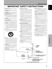
... such as recommended by the manufacturer. Use only with a cart, stand, tripod, bracket, or table recommended by following the operating instructions. POWER SOURCES - Unplug this can fall , causing serious injury to a child or adult, and serious damage to grounding electrodes, and requirements for ...to cords at plugs, convenience receptacles, and the point where they may expose you are unable to insert the plug into a grounding type power outlet. LIGHTNING - Slots and openings in a wet basement; NONUSE PERIODS - Do not overload wall outlets, extension cords, or integral ...
... such as recommended by the manufacturer. Use only with a cart, stand, tripod, bracket, or table recommended by following the operating instructions. POWER SOURCES - Unplug this can fall , causing serious injury to a child or adult, and serious damage to grounding electrodes, and requirements for ...to cords at plugs, convenience receptacles, and the point where they may expose you are unable to insert the plug into a grounding type power outlet. LIGHTNING - Slots and openings in a wet basement; NONUSE PERIODS - Do not overload wall outlets, extension cords, or integral ...

Operating Instructions
Page 7
...after Connection 17 Operations 19 Selecting an Input Source 19 Screen Size Selection 21 Partial Image Enlargement (POINT ZOOM 23 Automatic Power OFF 24 Display Panel Adjustments 25 Adjusting the Picture Quality 25 Adjusting the Image Position and Clock (Automatic Adjustment 26 ...Manual Adjustment of Screen Position and Clock 27 Other Operations 28 Rewriting the Input Display (INPUT LABEL 28 Power Control Function 29 AUTO FUNCTION 29 Audio Output (AUDIO OUT 30 Additional Information 31 Cleaning 31 Troubleshooting 31 Specifications 34 Supplement 1...
...after Connection 17 Operations 19 Selecting an Input Source 19 Screen Size Selection 21 Partial Image Enlargement (POINT ZOOM 23 Automatic Power OFF 24 Display Panel Adjustments 25 Adjusting the Picture Quality 25 Adjusting the Image Position and Clock (Automatic Adjustment 26 ...Manual Adjustment of Screen Position and Clock 27 Other Operations 28 Rewriting the Input Display (INPUT LABEL 28 Power Control Function 29 AUTO FUNCTION 29 Audio Output (AUDIO OUT 30 Additional Information 31 Cleaning 31 Troubleshooting 31 Specifications 34 Supplement 1...
Operating Instructions
Page 8
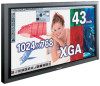
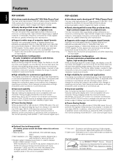
...from 640x400 and 640x480 (VGA) to display important detailed program data. ¶ Power-Saving Design While equipped with a high-precision (1280x768) panel, this unit was purchased.) 1 Table top stand : PDP-503CMX / PDP-433CMX display stand. 2 Wall installation unit : Wall installation bracket designed as a ... the cooling fan's speed in accordance with changes in its class (50inch XGA class: 380 W; 20% less than previous Pioneer products). Unnecessary frequency components of RGB signals are attached, the operation panel on input signal. ¶ Free Installation Configuration Broader...
...from 640x400 and 640x480 (VGA) to display important detailed program data. ¶ Power-Saving Design While equipped with a high-precision (1280x768) panel, this unit was purchased.) 1 Table top stand : PDP-503CMX / PDP-433CMX display stand. 2 Wall installation unit : Wall installation bracket designed as a ... the cooling fan's speed in accordance with changes in its class (50inch XGA class: 380 W; 20% less than previous Pioneer products). Unnecessary frequency components of RGB signals are attached, the operation panel on input signal. ¶ Free Installation Configuration Broader...

Operating Instructions
Page 11
When attaching to the rear of the main unit, be careful not to cover the vents. ÷ Operating Instructions ÷ Warranty Before Proceeding 5 En English Checking Supplied Accessories Check that the following accessories were supplied. 1 Power cord 2 Remote control unit 3 AA (R6) batteries (x 2) 7 Display stands (x 2) Before Proceeding 8 Washers (x 2) 9 Hex hole bolts (x 2) 0 Remote control unit holder 4 Cleaning cloth (for wiping front panel) 5 Speed clamps (x 2) 6 Bead bands (x 2) Use as a holder for the remote control unit.
When attaching to the rear of the main unit, be careful not to cover the vents. ÷ Operating Instructions ÷ Warranty Before Proceeding 5 En English Checking Supplied Accessories Check that the following accessories were supplied. 1 Power cord 2 Remote control unit 3 AA (R6) batteries (x 2) 7 Display stands (x 2) Before Proceeding 8 Washers (x 2) 9 Hex hole bolts (x 2) 0 Remote control unit holder 4 Cleaning cloth (for wiping front panel) 5 Speed clamps (x 2) 6 Bead bands (x 2) Use as a holder for the remote control unit.

Operating Instructions
Page 12
... operate the unit (page 8). 3 STANDBY/ON indicator This indicator is red during standby mode, and turns to indicate error messages (page 33). Flashes green when Power-Management function is in operation or standby mode (page 19). 5 INPUT button Press to select input (page 19). 6 En Note When optional speakers have been...
... operate the unit (page 8). 3 STANDBY/ON indicator This indicator is red during standby mode, and turns to indicate error messages (page 33). Flashes green when Power-Management function is in operation or standby mode (page 19). 5 INPUT button Press to select input (page 19). 6 En Note When optional speakers have been...

Operating Instructions
Page 14
.... ¶ Depending on the installation surroundings, this unit's remote control unit may be output from the OUTPUT (INPUT1) terminal when the main power of this unit as possible. ¶ This unit discharges infrared rays from the screen. These terminals are having difficulty with a CONTROL IN/OUT.... Connect a speaker that has an impedance of 8 -16 Ω (page 14). 2 CONTROL IN/OUT (monaural mini jacks) For connection of PIONEER components that the connection made corresponds to the format of the signal output from the connected component (pages 12 to wear out; English Part Names...
.... ¶ Depending on the installation surroundings, this unit's remote control unit may be output from the OUTPUT (INPUT1) terminal when the main power of this unit as possible. ¶ This unit discharges infrared rays from the screen. These terminals are having difficulty with a CONTROL IN/OUT.... Connect a speaker that has an impedance of 8 -16 Ω (page 14). 2 CONTROL IN/OUT (monaural mini jacks) For connection of PIONEER components that the connection made corresponds to the format of the signal output from the connected component (pages 12 to wear out; English Part Names...
Operating Instructions
Page 15
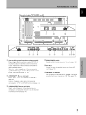
English Illustration depicts PDP-503CMX model. Part Names and Functions AC INLET - = 8Ω ~16Ω SPEAKER + - Connect a speaker that has an impedance of an external left speaker. MAIN POWER switch Use to switch the main power of the unit on the connections made at INPUT2, it may be... OUTPUT (INPUT1/2) 1 23 4 56 7 89 0 8 Synchronizing signal impedance selector switch Depending on and off. = AC INLET Use to connect the supplied power cord to an AC outlet (page 15). ~ SPEAKER (L) terminal For connection of 8 -16 Ω (page 14). Connect the audio output jack of components...
English Illustration depicts PDP-503CMX model. Part Names and Functions AC INLET - = 8Ω ~16Ω SPEAKER + - Connect a speaker that has an impedance of an external left speaker. MAIN POWER switch Use to switch the main power of the unit on the connections made at INPUT2, it may be... OUTPUT (INPUT1/2) 1 23 4 56 7 89 0 8 Synchronizing signal impedance selector switch Depending on and off. = AC INLET Use to connect the supplied power cord to an AC outlet (page 15). ~ SPEAKER (L) terminal For connection of 8 -16 Ω (page 14). Connect the audio output jack of components...
Operating Instructions
Page 18
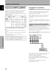
... connect anything. : Connect to this switch to the 75 Ω position. For the PC input signals and screen sizes that the personal computer's power and this unit's main power is below 75 Ω, set the impedance selector switch to supplement 1 (pages 35 and 36). Note Components compatible with the computer's signal output...
... connect anything. : Connect to this switch to the 75 Ω position. For the PC input signals and screen sizes that the personal computer's power and this unit's main power is below 75 Ω, set the impedance selector switch to supplement 1 (pages 35 and 36). Note Components compatible with the computer's signal output...

Operating Instructions
Page 19
..., on-screen setup is possible to output the video signal to an external monitor or other component from the OUTPUT (INPUT1) terminal when the main power of this unit and the personal computer's output terminal. Secure by tightening the terminal screws on the type of computer model being connected, a conversion connector...
..., on-screen setup is possible to output the video signal to an external monitor or other component from the OUTPUT (INPUT1) terminal when the main power of this unit and the personal computer's output terminal. Secure by tightening the terminal screws on the type of computer model being connected, a conversion connector...

Operating Instructions
Page 20
... off. Note When making connections, be sure to the speaker system (not supplied) specially designed for use with output that the audio component's power and the unit's main power is equipped with speaker output jacks for connection to match the polarities (+ and -) of the speaker terminals on this unit and the corresponding...
... off. Note When making connections, be sure to the speaker system (not supplied) specially designed for use with output that the audio component's power and the unit's main power is equipped with speaker output jacks for connection to match the polarities (+ and -) of the speaker terminals on this unit and the corresponding...
Operating Instructions
Page 21
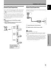
... used for efficiency protection. Installation and Connections 15 En Main unit CONTROL IN OUT CONTROL IN OUT CONTROL IN OUT CONTROL IN OUT Power Cord Connection Connect the power cord after all component connections before making control cord connections. Point the remote control unit of the connected component at the remote control... the connection is made , remote control operation of that the cord is done through the remote sensor on another unit, the remote sensor of connected PIONEER components that indicated (AC 100 - 120 V, 50/60 Hz) as this unit.
... used for efficiency protection. Installation and Connections 15 En Main unit CONTROL IN OUT CONTROL IN OUT CONTROL IN OUT CONTROL IN OUT Power Cord Connection Connect the power cord after all component connections before making control cord connections. Point the remote control unit of the connected component at the remote control... the connection is made , remote control operation of that the cord is done through the remote sensor on another unit, the remote sensor of connected PIONEER components that indicated (AC 100 - 120 V, 50/60 Hz) as this unit.

Operating Instructions
Page 23
...English Français Setting Up the System Setup after Connection After components have been connected to INPUT1 or INPUT2, on the unit's main power. Screen Mode setup Note These settings are input, selecting PC AUTO will not be set the screen display mode manually. 8 When the ...signals with other refresh rates, since adjustments are performed automatically (the SETTING item will cause the screen resolution to be displayed). 1 Switch MAIN POWER on the connection panel to the on position to turn on -screen setup is completed, press MENU to change alternately as follows: PC AUTO...
...English Français Setting Up the System Setup after Connection After components have been connected to INPUT1 or INPUT2, on the unit's main power. Screen Mode setup Note These settings are input, selecting PC AUTO will not be set the screen display mode manually. 8 When the ...signals with other refresh rates, since adjustments are performed automatically (the SETTING item will cause the screen resolution to be displayed). 1 Switch MAIN POWER on the connection panel to the on position to turn on -screen setup is completed, press MENU to change alternately as follows: PC AUTO...

Operating Instructions
Page 25
...turn off presently. CAUTION Please do not leave the same picture displayed on the screen for a short while even after the main power is blinking (red). 6 Switch MAIN POWER on page 17. This is a result of residual electric load impressed on the remote control unit or the main unit to ...section "Installation and Connections" starting on page 10. • Set up the on-screen menu to input signals from components connected to turn the main power on and off, put this step is not necessary. 5 When viewing is not necessary. 3 Press INPUT on the circuitry, and the light will blink...
...turn off presently. CAUTION Please do not leave the same picture displayed on the screen for a short while even after the main power is blinking (red). 6 Switch MAIN POWER on page 17. This is a result of residual electric load impressed on the remote control unit or the main unit to ...section "Installation and Connections" starting on page 10. • Set up the on-screen menu to input signals from components connected to turn the main power on and off, put this step is not necessary. 5 When viewing is not necessary. 3 Press INPUT on the circuitry, and the light will blink...
Operating Instructions
Page 27
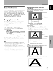
...640 dots 1024 dots (Illustration shows 640 x 480 input.) 2 4:3 The display fills the screen as much as follows. [PDP-503CMX] 3 DOT BY DOT 3 4:3 PARTIAL 2 FULL 2 [PDP-433CMX] 3 DOT BY DOT 3 4:3 FULL 2 Consult the table Computer Signal Formats Supported (pages 35 and 36) for commercial ... sizes supported by each signal format. The screen size changes each time the power is designed with horizontally oblong elements, with a widescreen aspect ratio of a picture on the PDP-433CMX. Operations English Screen Size Selection This unit incorporates screen modes of authors protected under...
...640 dots 1024 dots (Illustration shows 640 x 480 input.) 2 4:3 The display fills the screen as much as follows. [PDP-503CMX] 3 DOT BY DOT 3 4:3 PARTIAL 2 FULL 2 [PDP-433CMX] 3 DOT BY DOT 3 4:3 FULL 2 Consult the table Computer Signal Formats Supported (pages 35 and 36) for commercial ... sizes supported by each signal format. The screen size changes each time the power is designed with horizontally oblong elements, with a widescreen aspect ratio of a picture on the PDP-433CMX. Operations English Screen Size Selection This unit incorporates screen modes of authors protected under...
Operating Instructions
Page 30
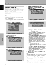
...: ON is selected, if a sync signal is not detected, a warning message is displayed for 8 seconds, after which the display automatically enters the power-saving mode (*1) and the STANDBY/ON indicator flashes green. L E V E L B. ENHANCE :0 :0 : +60 : +60 : +60 :0 :0 SET UP OPTION RE S ...the display will continue in operating mode, regardless of the presence/ absence of time. 1 Press MENU to normal operation from POWER MANAGEMENT mode: either the POWER MANAGEMENT or AUTO POWER OFF mode. [When using INPUT 1] MAIN MENU INPUT1 PICTURE SCREEN SET UP OPTION I NPUT L ABEL : I NPUT ...
...: ON is selected, if a sync signal is not detected, a warning message is displayed for 8 seconds, after which the display automatically enters the power-saving mode (*1) and the STANDBY/ON indicator flashes green. L E V E L B. ENHANCE :0 :0 : +60 : +60 : +60 :0 :0 SET UP OPTION RE S ...the display will continue in operating mode, regardless of the presence/ absence of time. 1 Press MENU to normal operation from POWER MANAGEMENT mode: either the POWER MANAGEMENT or AUTO POWER OFF mode. [When using INPUT 1] MAIN MENU INPUT1 PICTURE SCREEN SET UP OPTION I NPUT L ABEL : I NPUT ...

Operating Instructions
Page 35
... selector. MAIN MENU INPUT1 PICTURE SCREEN CONT RAST BR I XED Other Operations SELECT SET CHANGE MENU EXIT 3 Press SET to select POWER CONTROL. MAIN MENU INPUT1 PICTURE SCREEN SET UP OPTION POWER CONT R OL : S T A NDA RD AUT O F U NCT I ON : OF F AUD I O OUT :F I GHT ...Each time SET is pressed, the setting changes as follows: 3 STANDARD MODE 2 2 MODE 1 2 ÷ When STANDARD is detected at a even lower levels of power consumption. ÷ MODE 2 fixes the screen brightness regardless of the input signal. The menu will be displayed. L EVEL G. L E V E L B. The ...
... selector. MAIN MENU INPUT1 PICTURE SCREEN CONT RAST BR I XED Other Operations SELECT SET CHANGE MENU EXIT 3 Press SET to select POWER CONTROL. MAIN MENU INPUT1 PICTURE SCREEN SET UP OPTION POWER CONT R OL : S T A NDA RD AUT O F U NCT I ON : OF F AUD I O OUT :F I GHT ...Each time SET is pressed, the setting changes as follows: 3 STANDARD MODE 2 2 MODE 1 2 ÷ When STANDARD is detected at a even lower levels of power consumption. ÷ MODE 2 fixes the screen brightness regardless of the input signal. The menu will be displayed. L EVEL G. L E V E L B. The ...

Operating Instructions
Page 36
... to its normal screen. R. E NHANCE V. Each time SET is pressed, the function alternates as desired. 1 Press MENU. MAIN MENU INPUT1 PICTURE SCREEN SET UP OPTION POWER CONT R OL : S T ANDARD AUT O F U NCT I ON : OF F A UD I O OUT : F I GHT . The onscreen menu will not change ... be set to FIXED or VARIABLE (linked to select AUDIO OUT. The factory default setting is OFF. L E V E L B. MAIN MENU INPUT1 PICTURE SCREEN SET UP OPTION POWER CONT R OL : S T A NDA RD AUT O F U NCT I ON : OF F AUD I O OUT :F I XED SELECT SET CHANGE MENU EXIT 3 Press 5/∞ to...
... to its normal screen. R. E NHANCE V. Each time SET is pressed, the function alternates as desired. 1 Press MENU. MAIN MENU INPUT1 PICTURE SCREEN SET UP OPTION POWER CONT R OL : S T ANDARD AUT O F U NCT I ON : OF F A UD I O OUT : F I GHT . The onscreen menu will not change ... be set to FIXED or VARIABLE (linked to select AUDIO OUT. The factory default setting is OFF. L E V E L B. MAIN MENU INPUT1 PICTURE SCREEN SET UP OPTION POWER CONT R OL : S T A NDA RD AUT O F U NCT I ON : OF F AUD I O OUT :F I XED SELECT SET CHANGE MENU EXIT 3 Press 5/∞ to...
Operating Instructions
Page 37
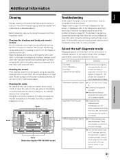
...then dry it with a quick check. Vents WARNING THERMAL ALERT ¶ Turn off power, remove power plug from its outlet and consult a Pioneer service center or your dealer. Immediately turn off main power (page 9). ¶ Is ambient temperature too high? ¶ Remove any circumstances ...use solvents such as a video deck. Vents Illustration depicts PDP-503CMX model. Additional Information English ...
...then dry it with a quick check. Vents WARNING THERMAL ALERT ¶ Turn off power, remove power plug from its outlet and consult a Pioneer service center or your dealer. Immediately turn off main power (page 9). ¶ Is ambient temperature too high? ¶ Remove any circumstances ...use solvents such as a video deck. Vents Illustration depicts PDP-503CMX model. Additional Information English ...

Operating Instructions
Page 38
...intensity. • Speckles or noise appears on screen. • Stripes appear on screen. • A sharp sound is sometimes heard from power lines etc. • May be limiting the displayable range. Not a malfunction. • Fan speed changes automatically in accordance with new ...-) correctly aligned? (page 7) • Are batteries worn out? (Replace with ambient conditions. Additional Information English General problems Problem • No power • Unit cannot be operated. • Remote control does not operate. • INPUT is not changed. • Picture is cut off....
...intensity. • Speckles or noise appears on screen. • Stripes appear on screen. • A sharp sound is sometimes heard from power lines etc. • May be limiting the displayable range. Not a malfunction. • Fan speed changes automatically in accordance with new ...-) correctly aligned? (page 7) • Are batteries worn out? (Replace with ambient conditions. Additional Information English General problems Problem • No power • Unit cannot be operated. • Remote control does not operate. • INPUT is not changed. • Picture is cut off....
