Operating Instructions
Page 5
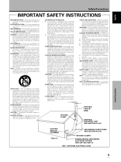
...or a soft dry cloth. The openings should be blocked by the product manufacturer as recommended by the manufacturer. POWER SOURCES - NONUSE PERIODS - The power cord of power supply to . If you are not sure of the type of the appliance should never be unplugged from the outlet... three-wire grounding type plug, a plug having one blade wider than the other electric light or power circuits, or where it will fit into such power lines or circuits. Power-supply cords should be blocked or covered. OUTDOOR ANTENNA GROUNDING - When installing an outside antenna system, extreme...
...or a soft dry cloth. The openings should be blocked by the product manufacturer as recommended by the manufacturer. POWER SOURCES - NONUSE PERIODS - The power cord of power supply to . If you are not sure of the type of the appliance should never be unplugged from the outlet... three-wire grounding type plug, a plug having one blade wider than the other electric light or power circuits, or where it will fit into such power lines or circuits. Power-supply cords should be blocked or covered. OUTDOOR ANTENNA GROUNDING - When installing an outside antenna system, extreme...

Operating Instructions
Page 7
...This Manual 3 Checking Supplied Accessories 5 Part Names and Functions 6 Main Unit 6 Remote Control Unit 7 Connection Panel 8 Installation and Connections 10 Installation of the Unit 10 Connection to INPUT1 and INPUT2 12 Audio Connections 14 Control Cord Connection 15 Power Cord Connection 15 How... Adjustment 26 Manual Adjustment of Screen Position and Clock 27 Other Operations 28 Rewriting the Input Display (INPUT LABEL 28 Power Control Function 29 AUTO FUNCTION 29 Audio Output (AUDIO OUT 30 Additional Information 31 Cleaning 31 Troubleshooting 31 Specifications 34 ...
...This Manual 3 Checking Supplied Accessories 5 Part Names and Functions 6 Main Unit 6 Remote Control Unit 7 Connection Panel 8 Installation and Connections 10 Installation of the Unit 10 Connection to INPUT1 and INPUT2 12 Audio Connections 14 Control Cord Connection 15 Power Cord Connection 15 How... Adjustment 26 Manual Adjustment of Screen Position and Clock 27 Other Operations 28 Rewriting the Input Display (INPUT LABEL 28 Power Control Function 29 AUTO FUNCTION 29 Audio Output (AUDIO OUT 30 Additional Information 31 Cleaning 31 Troubleshooting 31 Specifications 34 ...

Operating Instructions
Page 11
English Checking Supplied Accessories Check that the following accessories were supplied. 1 Power cord 2 Remote control unit 3 AA (R6) batteries (x 2) 7 Display stands (x 2) Before Proceeding 8 Washers (x 2) 9 Hex hole bolts (x 2) 0 Remote control unit holder 4 Cleaning cloth (for wiping front panel) 5 Speed clamps (x 2) 6 Bead bands (x 2) Use as a holder for the remote control unit. When attaching to the rear of the main unit, be careful not to cover the vents. ÷ Operating Instructions ÷ Warranty Before Proceeding 5 En
English Checking Supplied Accessories Check that the following accessories were supplied. 1 Power cord 2 Remote control unit 3 AA (R6) batteries (x 2) 7 Display stands (x 2) Before Proceeding 8 Washers (x 2) 9 Hex hole bolts (x 2) 0 Remote control unit holder 4 Cleaning cloth (for wiping front panel) 5 Speed clamps (x 2) 6 Bead bands (x 2) Use as a holder for the remote control unit. When attaching to the rear of the main unit, be careful not to cover the vents. ÷ Operating Instructions ÷ Warranty Before Proceeding 5 En
Operating Instructions
Page 15
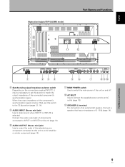
... this unit to an AC outlet (page 15). ~ SPEAKER (L) terminal For connection of 8 -16 Ω (page 14). MAIN POWER switch Use to switch the main power of the unit on the connections made at INPUT2, it may be necessary to set this switch to the 75 Ω position... INPUT OUTPUT (INPUT1/2) 1 23 4 56 7 89 0 8 Synchronizing signal impedance selector switch Depending on and off. = AC INLET Use to connect the supplied power cord to an AV amplifier or similar component (page 14). - Part Names and Functions AC INLET - = 8Ω ~16Ω SPEAKER + - English Illustration depicts...
... this unit to an AC outlet (page 15). ~ SPEAKER (L) terminal For connection of 8 -16 Ω (page 14). MAIN POWER switch Use to switch the main power of the unit on the connections made at INPUT2, it may be necessary to set this switch to the 75 Ω position... INPUT OUTPUT (INPUT1/2) 1 23 4 56 7 89 0 8 Synchronizing signal impedance selector switch Depending on and off. = AC INLET Use to connect the supplied power cord to an AV amplifier or similar component (page 14). - Part Names and Functions AC INLET - = 8Ω ~16Ω SPEAKER + - English Illustration depicts...

Operating Instructions
Page 20
... to the VD jack. Please see pages 17 and 18. Note When making composite SYNC connections, do not connect anything to the speaker system (not supplied) specially designed for use with this unit This unit features two audio inputs and one audio output. Sound is output from the • SPEAKER terminals... Connections English Installation and Connections Connection of composite SYNC analog RGB source Make composite SYNC connections for a personal computer with output that the audio component's power and the unit's main...
... to the VD jack. Please see pages 17 and 18. Note When making composite SYNC connections, do not connect anything to the speaker system (not supplied) specially designed for use with this unit This unit features two audio inputs and one audio output. Sound is output from the • SPEAKER terminals... Connections English Installation and Connections Connection of composite SYNC analog RGB source Make composite SYNC connections for a personal computer with output that the audio component's power and the unit's main...
Operating Instructions
Page 21
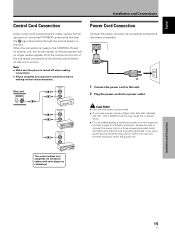
... signals. Installation and Connections 15 En When the connection is made , remote control operation of connected PIONEER components that component will no resistance). CAUTION ÷ Use only the power cord provided. ÷ Do not use an outlet with a ground terminal is properly grounded. The...component at the remote control sensor on this unit. 2 Plug the power cord into a power outlet. Always be sure to connect the power cord to control. If you use a power source converter plug, use a power supply voltage other than that the cord is used for efficiency protection. ...
... signals. Installation and Connections 15 En When the connection is made , remote control operation of connected PIONEER components that component will no resistance). CAUTION ÷ Use only the power cord provided. ÷ Do not use an outlet with a ground terminal is properly grounded. The...component at the remote control sensor on this unit. 2 Plug the power cord into a power outlet. Always be sure to connect the power cord to control. If you use a power source converter plug, use a power supply voltage other than that the cord is used for efficiency protection. ...
Operating Instructions
Page 37
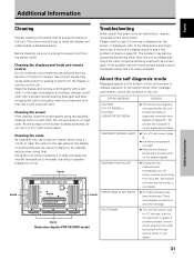
...depicts PDP-503CMX model. SHUT DOWN ¶ Turn off power, remove power plug from the display or remote control unit. If problem persists, remove power plug from the power outlet. In the case of dust will extend the life and performance of paint from its outlet, and consult a Pioneer service... center or your dealer. 31 En Cleaning the screen After dusting, wipe the screen gently using the supplied cleaning cloth or...
...depicts PDP-503CMX model. SHUT DOWN ¶ Turn off power, remove power plug from the display or remote control unit. If problem persists, remove power plug from the power outlet. In the case of dust will extend the life and performance of paint from its outlet, and consult a Pioneer service... center or your dealer. 31 En Cleaning the screen After dusting, wipe the screen gently using the supplied cleaning cloth or...
Operating Instructions
Page 40
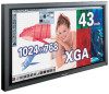
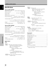
... notice. English Additional Information Specifications General (PDP-503CMX) Light emission panel 50 inch plasma display panel Number of pixels 1024 x 768 Power supply AC 100 - 120 V, 50/60 Hz Rated current 2.98 A - 2.48 A Standby power consumption 0.9 W External dimensions ........ 1070 ...including display stand 39.5 kg (87 lbs. 1 oz) General (PDP-433CMX) Light emission panel 43 inch plasma display panel Number of pixels 1280 x 768 Power supply AC 100 - 120 V, 50/60 Hz Rated current 3.8 A - 3.1 A Standby power consumption 1 W External dimensions ........ 1218 (W) x 714 (H) x...
... notice. English Additional Information Specifications General (PDP-503CMX) Light emission panel 50 inch plasma display panel Number of pixels 1024 x 768 Power supply AC 100 - 120 V, 50/60 Hz Rated current 2.98 A - 2.48 A Standby power consumption 0.9 W External dimensions ........ 1070 ...including display stand 39.5 kg (87 lbs. 1 oz) General (PDP-433CMX) Light emission panel 43 inch plasma display panel Number of pixels 1280 x 768 Power supply AC 100 - 120 V, 50/60 Hz Rated current 3.8 A - 3.1 A Standby power consumption 1 W External dimensions ........ 1218 (W) x 714 (H) x...
