Operating Instructions
Page 5
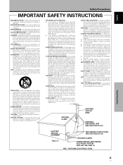
... to keep from overheating, and these openings must not be operated only from the wall outlet before the product is provided or the manufacturer's instructions have fallen into a grounding type power outlet. LOCATION - Power-supply cords should be routed so that are covered by the product manufacturer as radiators, heat registers, stoves, or other controls may cause hazards. OVERLOADING - REPLACEMENT PARTS - The...
... to keep from overheating, and these openings must not be operated only from the wall outlet before the product is provided or the manufacturer's instructions have fallen into a grounding type power outlet. LOCATION - Power-supply cords should be routed so that are covered by the product manufacturer as radiators, heat registers, stoves, or other controls may cause hazards. OVERLOADING - REPLACEMENT PARTS - The...

Operating Instructions
Page 7
... to Use This Manual 3 Checking Supplied Accessories 5 Part Names and Functions 6 Main Unit 6 Remote Control Unit 7 Connection Panel 8 Installation and Connections 10 Installation of the Unit 10 Connection to INPUT1 and INPUT2 12 Audio Connections 14 Control Cord Connection 15 Power Cord Connection 15 How to Route Cables 16 Setting Up the System 17 Setup after Connection 17 Operations 19 Selecting an Input Source 19 Screen Size Selection 21 Partial Image Enlargement (POINT ZOOM 23 Automatic Power OFF 24 Display Panel Adjustments 25 Adjusting the Picture...
... to Use This Manual 3 Checking Supplied Accessories 5 Part Names and Functions 6 Main Unit 6 Remote Control Unit 7 Connection Panel 8 Installation and Connections 10 Installation of the Unit 10 Connection to INPUT1 and INPUT2 12 Audio Connections 14 Control Cord Connection 15 Power Cord Connection 15 How to Route Cables 16 Setting Up the System 17 Setup after Connection 17 Operations 19 Selecting an Input Source 19 Screen Size Selection 21 Partial Image Enlargement (POINT ZOOM 23 Automatic Power OFF 24 Display Panel Adjustments 25 Adjusting the Picture...
Operating Instructions
Page 8
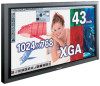
... operating mode (MODE 1, with color-bar signal input). Some of these include the one -touch screen adjustment, AUTO SETUP function for computer connections, and the POINT ZOOM function to enlarge local portions of the screen image to display important detailed program data. ¶ Power-Saving Design While equipped with a high-precision (1024x768) panel, this unit is not operable.) 2 En 4 Video card :Expansion card allows viewing of video signals and computer digital RGB signals (DVI compliant). 5 Cable cover :Dedicated cover to...
... operating mode (MODE 1, with color-bar signal input). Some of these include the one -touch screen adjustment, AUTO SETUP function for computer connections, and the POINT ZOOM function to enlarge local portions of the screen image to display important detailed program data. ¶ Power-Saving Design While equipped with a high-precision (1024x768) panel, this unit is not operable.) 2 En 4 Video card :Expansion card allows viewing of video signals and computer digital RGB signals (DVI compliant). 5 Cable cover :Dedicated cover to...
Operating Instructions
Page 9
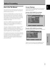
... with the plasma monitor and remote control unit, as shown: Example of PDP-433CMX Screen Display: ÷ The PDP-433CMX screen display fills the display area in this manual are the same for the PDP-503CMX model. L EV EL H. Screen Displays The example screen displays provided in both the PDP-503CMX and PDP-433CMX. L EVEL H. The section "Setting Up the System" starting on page 17 covers the necessary on page 10 covers all the parts have been...
... with the plasma monitor and remote control unit, as shown: Example of PDP-433CMX Screen Display: ÷ The PDP-433CMX screen display fills the display area in this manual are the same for the PDP-503CMX model. L EV EL H. Screen Displays The example screen displays provided in both the PDP-503CMX and PDP-433CMX. L EVEL H. The section "Setting Up the System" starting on page 17 covers the necessary on page 10 covers all the parts have been...

Operating Instructions
Page 12
... also used to green when the unit is in the on-screen display (pages 17 to 30). 8 SET button Press to optimum values (page 26). Usage of cursor buttons within operations is clearly indicated in the operation mode (page 19). English Part Names and Functions Main Unit Main unit 3 Operation panel on the main unit 4 5 6 7 8 9 0 Part Names and Functions 1 2 Main unit 1 Display stand 2 Remote control sensor...
... also used to green when the unit is in the on-screen display (pages 17 to 30). 8 SET button Press to optimum values (page 26). Usage of cursor buttons within operations is clearly indicated in the operation mode (page 19). English Part Names and Functions Main Unit Main unit 3 Operation panel on the main unit 4 5 6 7 8 9 0 Part Names and Functions 1 2 Main unit 1 Display stand 2 Remote control sensor...

Operating Instructions
Page 13
... English Part Names and Functions Remote Control Unit 1 7 8 2 9 3 0 4 5 6 - Please do not mix different kinds of batteries together. ¶ When not using computer signal input, automatically sets the POSITION and CLOCK/ PHASE to optimum values (page 26). 8 STANDBY/ON button Press to select and enlarge one part of cursor buttons within operations is removed, and then insert new batteries. ¶ Do not charge, short, disassemble...
... English Part Names and Functions Remote Control Unit 1 7 8 2 9 3 0 4 5 6 - Please do not mix different kinds of batteries together. ¶ When not using computer signal input, automatically sets the POSITION and CLOCK/ PHASE to optimum values (page 26). 8 STANDBY/ON button Press to select and enlarge one part of cursor buttons within operations is removed, and then insert new batteries. ¶ Do not charge, short, disassemble...

Operating Instructions
Page 14
... signal entirely. Part Names and Functions 8 En Audio input and speaker output jacks are objects placed between it at the remote sensor (Î) located on each item. 1 SPEAKER (R) terminal For connection of a personal computer (PC) or similar component. The remote control unit is used in the factory setup. 5 INPUT1 (mini D-sub 15 pin) For connection of an external right speaker. replace weak batteries with operation of PIONEER...
... signal entirely. Part Names and Functions 8 En Audio input and speaker output jacks are objects placed between it at the remote sensor (Î) located on each item. 1 SPEAKER (R) terminal For connection of a personal computer (PC) or similar component. The remote control unit is used in the factory setup. 5 INPUT1 (mini D-sub 15 pin) For connection of an external right speaker. replace weak batteries with operation of PIONEER...
Operating Instructions
Page 15
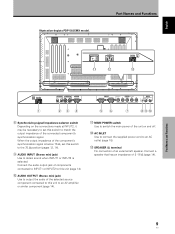
... left speaker. English Illustration depicts PDP-503CMX model. L ~ R 8Ω ~16Ω S+PEAKE-R CONTROL IN OUT COMBINATION IN OUT RS-232C INPUT1 (ON SYNC) ANALOG RGB OUTPUT (ANALOG RGB) G B INPUT2 (H/V SYNC) R HD VD 7Ω5Ô2k.Ω2 AUDIO INPUT OUTPUT (INPUT1/2) 1 23 4 56 7 89 0 8 Synchronizing signal impedance selector switch Depending on and off. = AC INLET Use to connect the supplied power cord to output the audio of the connected component's synchronization signal. Connect the audio output...
... left speaker. English Illustration depicts PDP-503CMX model. L ~ R 8Ω ~16Ω S+PEAKE-R CONTROL IN OUT COMBINATION IN OUT RS-232C INPUT1 (ON SYNC) ANALOG RGB OUTPUT (ANALOG RGB) G B INPUT2 (H/V SYNC) R HD VD 7Ω5Ô2k.Ω2 AUDIO INPUT OUTPUT (INPUT1/2) 1 23 4 56 7 89 0 8 Synchronizing signal impedance selector switch Depending on and off. = AC INLET Use to connect the supplied power cord to output the audio of the connected component's synchronization signal. Connect the audio output...
Operating Instructions
Page 18
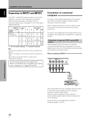
... output impedance of separate SYNC analog RGB source Make separate SYNC connections for information regarding settings. INPUT2 [ON SYNC] Output jack G B source Personal computer (PC) with RGB output G ON SYNC B [H/V SYNC] R HD VD R G B R H/V SYNC G B R HD VD : Do not connect anything. : Connect to supplement 1 (pages 35 and 36). For the PC input signals and screen sizes that has RGB output separated into 5 output signals: green, blue, red, horizontal synchronization signal, and vertical synchronization signal. On-screen setup is compatible with , please refer to...
... output impedance of separate SYNC analog RGB source Make separate SYNC connections for information regarding settings. INPUT2 [ON SYNC] Output jack G B source Personal computer (PC) with RGB output G ON SYNC B [H/V SYNC] R HD VD R G B R H/V SYNC G B R HD VD : Do not connect anything. : Connect to supplement 1 (pages 35 and 36). For the PC input signals and screen sizes that has RGB output separated into 5 output signals: green, blue, red, horizontal synchronization signal, and vertical synchronization signal. On-screen setup is compatible with , please refer to...

Operating Instructions
Page 19
.... On screen setup is necessary. When connecting to INPUT1 INPUT1 OUTPUT ANALOG RGB (ANALOG RGB) Connect the cable corresponding to INPUT1 INPUT1 OUTPUT ANALOG RGB (ANALOG RGB) Installation and Connections Connection of G ON SYNC analog RGB source Make G ON SYNC connections for a personal computer with the computer or sold separately may be necessary. provided with output that has the synchronization signal layered on top of the green signal. Please see pages 17 and 18. English Franç...
.... On screen setup is necessary. When connecting to INPUT1 INPUT1 OUTPUT ANALOG RGB (ANALOG RGB) Connect the cable corresponding to INPUT1 INPUT1 OUTPUT ANALOG RGB (ANALOG RGB) Installation and Connections Connection of G ON SYNC analog RGB source Make G ON SYNC connections for a personal computer with the computer or sold separately may be necessary. provided with output that has the synchronization signal layered on top of the green signal. Please see pages 17 and 18. English Franç...

Operating Instructions
Page 20
... audio inputs and one audio output. On-screen setup is necessary after connection. Installation and Connections English Installation and Connections Connection of composite SYNC analog RGB source Make composite SYNC connections for a personal computer with output that the audio component's power and the unit's main power is off. Please see pages 17 and 18. When the output impedance of the computer's synchronization signal is below when making speaker connections, be sure to check that has the vertical synchronization signal...
... audio inputs and one audio output. On-screen setup is necessary after connection. Installation and Connections English Installation and Connections Connection of composite SYNC analog RGB source Make composite SYNC connections for a personal computer with output that the audio component's power and the unit's main power is off. Please see pages 17 and 18. When the output impedance of the computer's synchronization signal is below when making speaker connections, be sure to check that has the vertical synchronization signal...
Operating Instructions
Page 21
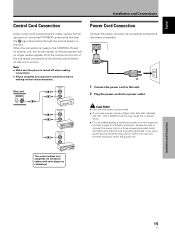
... plug, use a power supply voltage other than that component will no resistance). English Français Installation and Connections Control Cord Connection When control cord connections are monaural cables with a ground terminal is used for efficiency protection. Always be sure to connect the power cord to control. When the connection is made , remote control operation of that indicated (AC 100 - 120 V, 50/60 Hz) as this unit. Notes ÷ Make sure the power is turned...
... plug, use a power supply voltage other than that component will no resistance). English Français Installation and Connections Control Cord Connection When control cord connections are monaural cables with a ground terminal is used for efficiency protection. Always be sure to connect the power cord to control. When the connection is made , remote control operation of that indicated (AC 100 - 120 V, 50/60 Hz) as this unit. Notes ÷ Make sure the power is turned...

Operating Instructions
Page 23
... the System Setup after Connection After components have been connected to select SET UP. Screen Mode setup Note These settings are input, selecting PC AUTO will cause the display mode to change alternately as follows: PC AUTO XGA WIDE XGA 3 When the input signal has a refresh rate of components connected. The STANDBY/ON indicator turns green. 3 Select INPUT1 or INPUT2. 4 Press MENU to put the unit in the operation mode. MAIN MENU INPUT1 PICTURE SCREEN SET UP OPTION...
... the System Setup after Connection After components have been connected to select SET UP. Screen Mode setup Note These settings are input, selecting PC AUTO will cause the display mode to change alternately as follows: PC AUTO XGA WIDE XGA 3 When the input signal has a refresh rate of components connected. The STANDBY/ON indicator turns green. 3 Select INPUT1 or INPUT2. 4 Press MENU to put the unit in the operation mode. MAIN MENU INPUT1 PICTURE SCREEN SET UP OPTION...

Operating Instructions
Page 24
... ÷ Make this CLAMP POSITION setting for each time SET is pressed. 3 AUTO LOCKED 2 5 When the setup is completed, press MENU to carefully check the signal output of CLAMP POSITION 1 Press MENU to select SET UP. English Setting Up the System CLAMP POSITION setup Depending on the signal, analog RGB signals may result in the screen image appearing with the component you are connecting. The menu screen appears. MAIN MENU PICTURE SCREEN CONT RAST BR I NG : VGA SELECT SET CHANGE MENU EXIT Setting Up...
... ÷ Make this CLAMP POSITION setting for each time SET is pressed. 3 AUTO LOCKED 2 5 When the setup is completed, press MENU to carefully check the signal output of CLAMP POSITION 1 Press MENU to select SET UP. English Setting Up the System CLAMP POSITION setup Depending on the signal, analog RGB signals may result in the screen image appearing with the component you are connecting. The menu screen appears. MAIN MENU PICTURE SCREEN CONT RAST BR I NG : VGA SELECT SET CHANGE MENU EXIT Setting Up...

Operating Instructions
Page 25
... "Installation and Connections" starting on page 10. • Set up the on-screen menu to input signals from components connected to INPUT1 and INPUT2 as "screen burn" which leaves a ghost, or residual, image of the picture on the circuitry, and the light will turn off presently. The STANDBY/ON indicator lights red. 2 Press STANDBY/ON to put the unit in standby mode. The STANDBY/ON indicator will blink...
... "Installation and Connections" starting on page 10. • Set up the on-screen menu to input signals from components connected to INPUT1 and INPUT2 as "screen burn" which leaves a ghost, or residual, image of the picture on the circuitry, and the light will turn off presently. The STANDBY/ON indicator lights red. 2 Press STANDBY/ON to put the unit in standby mode. The STANDBY/ON indicator will blink...

Operating Instructions
Page 31
.... :0 ADJUST SET SET MENU EXIT 4 Press SET. L EVEL H. CONTRAST Adjust according to the surrounding brightness so that can be seen clearly. LEVEL Adjust the amount of green in the previous procedure, press 5/∞ to make adjustments under already adjusted conditions. 1 In step 2 in the picture. NO SELECT SET SET MENU EXIT 2 Press 2/3 to display the menu screen. All PICTURE mode settings are brief descriptions of the picture can be set default. 25 En B. H. E NHANCE V. L EVEL G. English Display Panel Adjustments Adjusting the Picture...
.... :0 ADJUST SET SET MENU EXIT 4 Press SET. L EVEL H. CONTRAST Adjust according to the surrounding brightness so that can be seen clearly. LEVEL Adjust the amount of green in the previous procedure, press 5/∞ to make adjustments under already adjusted conditions. 1 In step 2 in the picture. NO SELECT SET SET MENU EXIT 2 Press 2/3 to display the menu screen. All PICTURE mode settings are brief descriptions of the picture can be set default. 25 En B. H. E NHANCE V. L EVEL G. English Display Panel Adjustments Adjusting the Picture...

Operating Instructions
Page 33
... SET ENTER MENU EXIT 4 Press 2/3 to the input video signal. Display Panel Adjustments 5 Press SET. This setting adjusts the phase of the options that can be displayed properly. Display Panel Adjustments H. V.POSITION Adjust the picture's position upward or downward. English Manual Adjustment of screen letters or color misalignment. Pressing SET writes the value into the memory and returns the display to the step 3 screen. 6 When adjustment is minimum flicker of Screen Position and Clock 1 Press MENU to default settings instead of V.POSITION and PHASE. PHASE Adjust...
... SET ENTER MENU EXIT 4 Press 2/3 to the input video signal. Display Panel Adjustments 5 Press SET. This setting adjusts the phase of the options that can be displayed properly. Display Panel Adjustments H. V.POSITION Adjust the picture's position upward or downward. English Manual Adjustment of screen letters or color misalignment. Pressing SET writes the value into the memory and returns the display to the step 3 screen. 6 When adjustment is minimum flicker of Screen Position and Clock 1 Press MENU to default settings instead of V.POSITION and PHASE. PHASE Adjust...
Operating Instructions
Page 37
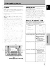
... and check the mode. Using the unit without cleaning it with a dry soft cloth. Vents Illustration depicts PDP-503CMX model. WARNING FAN FAILURE ¶ Cooling fan has malfunctioned. Immediately turn off main power, wait for cleaner. Before cleaning, be an malfunction, may cause deterioration or peeling of the unit. If displayed, refer to unplug the power cord from the display or remote control unit. Troubleshooting What...
... and check the mode. Using the unit without cleaning it with a dry soft cloth. Vents Illustration depicts PDP-503CMX model. WARNING FAN FAILURE ¶ Cooling fan has malfunctioned. Immediately turn off main power, wait for cleaner. Before cleaning, be an malfunction, may cause deterioration or peeling of the unit. If displayed, refer to unplug the power cord from the display or remote control unit. Troubleshooting What...

Operating Instructions
Page 38
... problems Problem • No power • Unit cannot be operated. • Remote control does not operate. • INPUT is not changed. • Picture is cut off. • Strange color, light color, or dark, or color misalignment • Power is suddenly turned off , or unplugging the power cord and re-plugging it in after 1 to 2 minutes. • Normal sound of the cooling fan and internal sliding parts of the plasma display panel...
... problems Problem • No power • Unit cannot be operated. • Remote control does not operate. • INPUT is not changed. • Picture is cut off. • Strange color, light color, or dark, or color misalignment • Power is suddenly turned off , or unplugging the power cord and re-plugging it in after 1 to 2 minutes. • Normal sound of the cooling fan and internal sliding parts of the plasma display panel...
Operating Instructions
Page 39
...; If the power is automatically turned off and change in event of time. In this case, unplug the power cord from the power outlet and request repair from a chilled location to dry thoroughly before using the monitor in this display is very bright and viewing it a close distance will flash red for advice. STANDBY/ON indicator During operation of time. After-image (lag image) due to...
...; If the power is automatically turned off and change in event of time. In this case, unplug the power cord from the power outlet and request repair from a chilled location to dry thoroughly before using the monitor in this display is very bright and viewing it a close distance will flash red for advice. STANDBY/ON indicator During operation of time. After-image (lag image) due to...
