
Operating Instructions
Page 7
... Power Cord Connection 15 How to Route Cables 16 Setting Up the System 17 Setup after Connection 17 Operations 19 Selecting an Input Source 19 Screen Size Selection 21 Partial Image Enlargement (POINT ZOOM 23 Automatic Power OFF 24 Display Panel Adjustments 25 Adjusting the...Adjusting the Image Position and Clock (Automatic Adjustment 26 Manual Adjustment of Screen Position and Clock 27 Other Operations 28 Rewriting the Input Display (INPUT LABEL 28 Power Control Function 29 AUTO FUNCTION 29 Audio Output (AUDIO OUT 30 Additional Information 31 Cleaning 31 Troubleshooting 31 ...
... Power Cord Connection 15 How to Route Cables 16 Setting Up the System 17 Setup after Connection 17 Operations 19 Selecting an Input Source 19 Screen Size Selection 21 Partial Image Enlargement (POINT ZOOM 23 Automatic Power OFF 24 Display Panel Adjustments 25 Adjusting the...Adjusting the Image Position and Clock (Automatic Adjustment 26 Manual Adjustment of Screen Position and Clock 27 Other Operations 28 Rewriting the Input Display (INPUT LABEL 28 Power Control Function 29 AUTO FUNCTION 29 Audio Output (AUDIO OUT 30 Additional Information 31 Cleaning 31 Troubleshooting 31 ...
Operating Instructions
Page 8
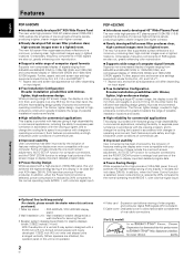
...line (sold separately) (For details, please consult the dealer where this unit was purchased.) 1 Table top stand : PDP-503CMX / PDP-433CMX display stand. 2 Wall installation unit : Wall installation bracket designed as a wall interface for securing the unit. 3...32 inch (4.5 cm) wide oval shaped units arranged vertically. (When speakers are attached, the operation panel on input signal. ¶ Free Installation Configuration Broader installation possibilities with thinner, lighter, high-endurance design. The thinner, lighter... (50inch XGA class: 380 W; 20% less than previous Pioneer products).
...line (sold separately) (For details, please consult the dealer where this unit was purchased.) 1 Table top stand : PDP-503CMX / PDP-433CMX display stand. 2 Wall installation unit : Wall installation bracket designed as a wall interface for securing the unit. 3...32 inch (4.5 cm) wide oval shaped units arranged vertically. (When speakers are attached, the operation panel on input signal. ¶ Free Installation Configuration Broader installation possibilities with thinner, lighter, high-endurance design. The thinner, lighter... (50inch XGA class: 380 W; 20% less than previous Pioneer products).

Operating Instructions
Page 10
... on the main unit. English Before Proceeding About operations in this manual Operations in this manual are outlined in screen displays may vary depending on input source and specific settings. Please familiarize yourself with this manual. 1 Press MENU to be used when performing operations. H. R. MAIN MENU PICTURE SCREEN POS I T I ON : CL...
... on the main unit. English Before Proceeding About operations in this manual Operations in this manual are outlined in screen displays may vary depending on input source and specific settings. Please familiarize yourself with this manual. 1 Press MENU to be used when performing operations. H. R. MAIN MENU PICTURE SCREEN POS I T I ON : CL...

Operating Instructions
Page 12
...page 24). Operation panel on the main unit 4 STANDBY/ON button Press to put the display in operation or standby mode (page 19). 5 INPUT button Press to select input (page 19). 6 En Note When optional speakers have been connected, the operation panel on the main unit will not be operable. 6 MENU ...unit (pages 17 to 30). 9 SCREEN SIZE button Press to select the screen size (page 21). 0 AUTO SET UP button When using computer signal input, automatically sets the POSITION and CLOCK/PHASE to adjust various settings on the unit. English Part Names and Functions Main Unit Main unit 3 Operation panel...
...page 24). Operation panel on the main unit 4 STANDBY/ON button Press to put the display in operation or standby mode (page 19). 5 INPUT button Press to select input (page 19). 6 En Note When optional speakers have been connected, the operation panel on the main unit will not be operable. 6 MENU ...unit (pages 17 to 30). 9 SCREEN SIZE button Press to select the screen size (page 21). 0 AUTO SET UP button When using computer signal input, automatically sets the POSITION and CLOCK/PHASE to adjust various settings on the unit. English Part Names and Functions Main Unit Main unit 3 Operation panel...

Operating Instructions
Page 13
... batteries in the direction of batteries may differ even if they are the same shape. Usage of batteries together. ¶ When not using computer signal input, automatically sets the POSITION and CLOCK/ PHASE to optimum values (page 26). 8 STANDBY/ON button Press to put the unit in the battery case. &#...with used batteries, please comply with new ones as soon as possible. 1 SCREEN SIZE button Press to select the screen size (page 21). 2 INPUT buttons Use to select the input (page 19). 3 MENU button Press to open and close the on the unit (pages 17 to 30). 6 MUTING button Press to mute...
... batteries in the direction of batteries may differ even if they are the same shape. Usage of batteries together. ¶ When not using computer signal input, automatically sets the POSITION and CLOCK/ PHASE to optimum values (page 26). 8 STANDBY/ON button Press to put the unit in the battery case. &#...with used batteries, please comply with new ones as soon as possible. 1 SCREEN SIZE button Press to select the screen size (page 21). 2 INPUT buttons Use to select the input (page 19). 3 MENU button Press to open and close the on the unit (pages 17 to 30). 6 MUTING button Press to mute...

Operating Instructions
Page 14
...will not be influenced by an infrared remote control unit near this unit may be output from the plasma display, hampering reception of PIONEER components that the connection made corresponds to a position further away from the screen. Make sure that bear the Î mark. ...speaker output jacks are having difficulty with two video input jacks and one video output jack. Placing a video deck or other component. Making CONTROL connection enables control of the signal output from the screen will differ according to PIONEER components bearing the Î mark. Make sure ...
...will not be influenced by an infrared remote control unit near this unit may be output from the plasma display, hampering reception of PIONEER components that the connection made corresponds to a position further away from the screen. Make sure that bear the Î mark. ...speaker output jacks are having difficulty with two video input jacks and one video output jack. Placing a video deck or other component. Making CONTROL connection enables control of the signal output from the screen will differ according to PIONEER components bearing the Î mark. Make sure ...
Operating Instructions
Page 15
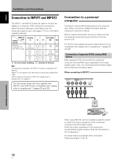
...sound when INPUT1 or INPUT2 is below 75 Ω, set this unit to an AV amplifier or similar component (page 14). - English Illustration depicts PDP-503CMX model. Part Names and Functions 9 En L ~ R 8Ω ~16Ω S+PEAKE-R CONTROL IN OUT COMBINATION IN OUT RS-232C ...INPUT1 (ON SYNC) ANALOG RGB OUTPUT (ANALOG RGB) G B INPUT2 (H/V SYNC) R HD VD 7Ω5Ô2k.Ω2 AUDIO INPUT OUTPUT (INPUT1/2) 1 23 4 56 7 89 0 8 Synchronizing signal impedance selector switch Depending on and off. = AC INLET Use to connect the supplied ...
...sound when INPUT1 or INPUT2 is below 75 Ω, set this unit to an AV amplifier or similar component (page 14). - English Illustration depicts PDP-503CMX model. Part Names and Functions 9 En L ~ R 8Ω ~16Ω S+PEAKE-R CONTROL IN OUT COMBINATION IN OUT RS-232C ...INPUT1 (ON SYNC) ANALOG RGB OUTPUT (ANALOG RGB) G B INPUT2 (H/V SYNC) R HD VD 7Ω5Ô2k.Ω2 AUDIO INPUT OUTPUT (INPUT1/2) 1 23 4 56 7 89 0 8 Synchronizing signal impedance selector switch Depending on and off. = AC INLET Use to connect the supplied ...
Operating Instructions
Page 18
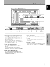
INPUT2 [ON SYNC] Output jack G B source Personal computer (PC) with Microsoft's Plug & Play (VESA DDC 1/2B). For the PC input signals and screen sizes that this unit is off. On-screen setup is compatible with RGB output G ON SYNC B [H/V SYNC] R HD VD R G B R H/V SYNC ...for a personal computer that the personal computer's power and this switch to supplement 2 on the computer type. For the screen sizes and input signals that INPUT1 and INPUT2 are used to connect the display to a computer. Before making the connections, adjust the screen settings in accordance...
INPUT2 [ON SYNC] Output jack G B source Personal computer (PC) with Microsoft's Plug & Play (VESA DDC 1/2B). For the PC input signals and screen sizes that this unit is off. On-screen setup is compatible with RGB output G ON SYNC B [H/V SYNC] R HD VD R G B R H/V SYNC ...for a personal computer that the personal computer's power and this switch to supplement 2 on the computer type. For the screen sizes and input signals that INPUT1 and INPUT2 are used to connect the display to a computer. Before making the connections, adjust the screen settings in accordance...

Operating Instructions
Page 19
... your computer. On screen setup is necessary after connection. Note When making G ON SYNC connections, do not make any connections to the shape of the input terminal on top of the green signal.
... your computer. On screen setup is necessary after connection. Note When making G ON SYNC connections, do not make any connections to the shape of the input terminal on top of the green signal.

Operating Instructions
Page 20
...screen setup is necessary after connection. With this type of component, please connect using INPUT2, set this unit. Video Audio input jacks input Sound output INPUT1 INPUT2 Stereo mini jack (L/R) Sound of the horizontal synchronization signal. Sound is below when making connections, be...Push tab to secure the wire in place. Audio connections for component (computer) connected to INPUT 1 or INPUT 2 AUDIO VD INPUT OUTPUT 7Ω5Ô2k.Ω2 (INPUT1/2) Audio input to the AUDIO INPUT jacks (stereo mini jack) is reversed, the sound will be displayed properly. ÷...
...screen setup is necessary after connection. With this type of component, please connect using INPUT2, set this unit. Video Audio input jacks input Sound output INPUT1 INPUT2 Stereo mini jack (L/R) Sound of the horizontal synchronization signal. Sound is below when making connections, be...Push tab to secure the wire in place. Audio connections for component (computer) connected to INPUT 1 or INPUT 2 AUDIO VD INPUT OUTPUT 7Ω5Ô2k.Ω2 (INPUT1/2) Audio input to the AUDIO INPUT jacks (stereo mini jack) is reversed, the sound will be displayed properly. ÷...

Operating Instructions
Page 23
... SET ENTER MENU EXIT 6 Press 5/∞ to VGA or XGA only. Note The PC AUTO setting supports automatic signal selection only when using the following input signal refresh rates: 1 31.5 kHz horizontal / 60 Hz vertical; 2 48.4 kHz horizontal / 60 Hz vertical; 3 56.5 kHz horizontal / 70 Hz vertical. L E...GHT . E NHANCE V. The menu screen appears. When G ON SYNC or Composite Sync signals are required only when using RGB separate Sync inputs. L EVEL G. Setting Up the System English Français Setting Up the System Setup after Connection After components have been connected to ...
... SET ENTER MENU EXIT 6 Press 5/∞ to VGA or XGA only. Note The PC AUTO setting supports automatic signal selection only when using the following input signal refresh rates: 1 31.5 kHz horizontal / 60 Hz vertical; 2 48.4 kHz horizontal / 60 Hz vertical; 3 56.5 kHz horizontal / 70 Hz vertical. L E...GHT . E NHANCE V. The menu screen appears. When G ON SYNC or Composite Sync signals are required only when using RGB separate Sync inputs. L EVEL G. Setting Up the System English Français Setting Up the System Setup after Connection After components have been connected to ...

Operating Instructions
Page 24
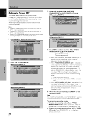
... R MA NAGEME NT : OF F CL AMP P OS I T I ON : AU T O SETT I NG : VGA SELECT SET CHANGE MENU EXIT Mode selection will change as follows each applicable input (INPUT1 and INPUT2). ÷ When using . Notes ÷ Make this CLAMP POSITION setting for each time SET is pressed. 3 AUTO LOCKED 2 5 When the setup is...
... R MA NAGEME NT : OF F CL AMP P OS I T I ON : AU T O SETT I NG : VGA SELECT SET CHANGE MENU EXIT Mode selection will change as follows each applicable input (INPUT1 and INPUT2). ÷ When using . Notes ÷ Make this CLAMP POSITION setting for each time SET is pressed. 3 AUTO LOCKED 2 5 When the setup is...

Operating Instructions
Page 25
... and personal computer as described in the section "Installation and Connections" starting on page 10. • Set up the on-screen menu to input signals from components connected to INPUT1 and INPUT2 as described in the section "Setting Up the System" on the remote control unit to adjust the... is blinking (red). 6 Switch MAIN POWER on the screen. 19 En Doing so may continue to turn off presently. English Operations Selecting an Input Source This section explains the basic operation of this unit in the operation mode. Outlined on the following pages is not supported by the display...
... and personal computer as described in the section "Installation and Connections" starting on page 10. • Set up the on-screen menu to input signals from components connected to INPUT1 and INPUT2 as described in the section "Setting Up the System" on the remote control unit to adjust the... is blinking (red). 6 Switch MAIN POWER on the screen. 19 En Doing so may continue to turn off presently. English Operations Selecting an Input Source This section explains the basic operation of this unit in the operation mode. Outlined on the following pages is not supported by the display...

Operating Instructions
Page 26
V OLU ME :5 To mute the sound Press DISPLAY on the remote control unit. The currently selected input, screen size and refresh rates will be slightly different from actual values. Press MUTING again to adjust the volume of the connected speakers. DISPLAY Operations ...
V OLU ME :5 To mute the sound Press DISPLAY on the remote control unit. The currently selected input, screen size and refresh rates will be slightly different from actual values. Press MUTING again to adjust the volume of the connected speakers. DISPLAY Operations ...
Operating Instructions
Page 27
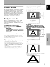
...] A 480 lines 768 lines 640 dots 1280 dots (Illustration shows 640 x 480 input.) [PDP-433CMX] * The PDP-433CMX is moved slightly each signal format. A 21 En Operations Press SCREEN SIZE to display a non- Notes ÷ When the PARTIAL or ... as possible without altering the aspect ratio of a picture on the PDP-433CMX. A 480 lines 768 lines 640 dots 1024 dots (Illustration shows 640 x 480 input.) 2 4:3 The display fills the screen as much as follows. [PDP-503CMX] 3 DOT BY DOT 3 4:3 PARTIAL 2 FULL 2 [PDP-433CMX] 3 DOT BY DOT 3 4:3 FULL 2 Consult the table Computer...
...] A 480 lines 768 lines 640 dots 1280 dots (Illustration shows 640 x 480 input.) [PDP-433CMX] * The PDP-433CMX is moved slightly each signal format. A 21 En Operations Press SCREEN SIZE to display a non- Notes ÷ When the PARTIAL or ... as possible without altering the aspect ratio of a picture on the PDP-433CMX. A 480 lines 768 lines 640 dots 1024 dots (Illustration shows 640 x 480 input.) 2 4:3 The display fills the screen as much as follows. [PDP-503CMX] 3 DOT BY DOT 3 4:3 PARTIAL 2 FULL 2 [PDP-433CMX] 3 DOT BY DOT 3 4:3 FULL 2 Consult the table Computer...

Operating Instructions
Page 28
... lines 1024 lines Use 5/∞ to the source. Moving the screen position upward or downward (*Supported only on PDP-503CMX) The PARTIAL setting is available only during personal computer input (1280 x 1024/60 Hz only). Display is highly faithful to adjust the position of the video image on ...the screen. English Operations 4 PARTIAL (*Supported only on PDP-503CMX) During personal computer input (1280 x 1024/60Hz only), even when the PARTIAL setting is selected, the position of the screen can be stored in order ...
... lines 1024 lines Use 5/∞ to the source. Moving the screen position upward or downward (*Supported only on PDP-503CMX) The PARTIAL setting is available only during personal computer input (1280 x 1024/60 Hz only). Display is highly faithful to adjust the position of the video image on ...the screen. English Operations 4 PARTIAL (*Supported only on PDP-503CMX) During personal computer input (1280 x 1024/60Hz only), even when the PARTIAL setting is selected, the position of the screen can be stored in order ...

Operating Instructions
Page 29
... AREA 7 x 4.0 x 2.0 x 1.5 x 3.0 AREA 8 x 4.0 x 2.0 x 1.5 x 3.0 x 3.0 AREA 9 x 4.0 x 2.0 x 1.5 23 En SELECT P.ZOOM SET EXIT ZOOM Note Whenever point zoom is displayed, or the INPUT changes. When performing point zoom enlargement, the direction buttons (5/∞/2/3) can be pressed again if desired to change the zoom ratio or display position. 4 Press...no operation is undertaken for three seconds or more, the display screen will also be canceled whenever the input signal changes, the menu screen is selected, the screen size automatically changes to FULL. 2 Press 5/∞...
... AREA 7 x 4.0 x 2.0 x 1.5 x 3.0 AREA 8 x 4.0 x 2.0 x 1.5 x 3.0 x 3.0 AREA 9 x 4.0 x 2.0 x 1.5 23 En SELECT P.ZOOM SET EXIT ZOOM Note Whenever point zoom is displayed, or the INPUT changes. When performing point zoom enlargement, the direction buttons (5/∞/2/3) can be pressed again if desired to change the zoom ratio or display position. 4 Press...no operation is undertaken for three seconds or more, the display screen will also be canceled whenever the input signal changes, the menu screen is selected, the screen size automatically changes to FULL. 2 Press 5/∞...
Operating Instructions
Page 30
... screen. L E V E L B. L EVEL H. Note The POWER MANAGEMENT and AUTO POWER OFF functions must be set individually for each input (INPUT 1 or INPUT 2). To return to operating mode: ÷ To return to normal operation from POWER MANAGEMENT mode: either the POWER MANAGEMENT or AUTO POWER OFF...I NPUT L A BEL : I NPUT 1 POWE R MA NAGEME NT : OF F CL AMP P OS I T I ON : AU T O SETT I NG : VGA SELECT SET ENTER MENU EXIT [When using INPUT 2] MAIN MENU INPUT2 PICTURE SCREEN SET UP OPTION I NPUT L ABEL : I NPUT 2 A UTO POWE R OF F : OF F CL AMP P OS I T I ON : AU T O SETT I GHT ...
... screen. L E V E L B. L EVEL H. Note The POWER MANAGEMENT and AUTO POWER OFF functions must be set individually for each input (INPUT 1 or INPUT 2). To return to operating mode: ÷ To return to normal operation from POWER MANAGEMENT mode: either the POWER MANAGEMENT or AUTO POWER OFF...I NPUT L A BEL : I NPUT 1 POWE R MA NAGEME NT : OF F CL AMP P OS I T I ON : AU T O SETT I NG : VGA SELECT SET ENTER MENU EXIT [When using INPUT 2] MAIN MENU INPUT2 PICTURE SCREEN SET UP OPTION I NPUT L ABEL : I NPUT 2 A UTO POWE R OF F : OF F CL AMP P OS I T I ON : AU T O SETT I GHT ...

Operating Instructions
Page 31
... signals. BRIGHT Adjust so that the picture can be seen clearly. ENHANCE Sharpens the image in the vertical direction. Note Make these adjustments for each input (INPUT1 to exit the menu screen. MAIN MENU PICTURE SCREEN CONT RAST B R I GHT. :0 ADJUST SET SET MENU EXIT 4 Press SET...
... signals. BRIGHT Adjust so that the picture can be seen clearly. ENHANCE Sharpens the image in the vertical direction. Note Make these adjustments for each input (INPUT1 to exit the menu screen. MAIN MENU PICTURE SCREEN CONT RAST B R I GHT. :0 ADJUST SET SET MENU EXIT 4 Press SET...

Operating Instructions
Page 32
... Remote Control Unit Press AUTO SET UP on either the main unit or remote control unit. ÷ Optimum settings may not be possible for each input function (INPUT 1, INPUT 2), and each signal type. Note Perform this case, follow the instructions in the section "Manual Adjustment of signals.
... Remote Control Unit Press AUTO SET UP on either the main unit or remote control unit. ÷ Optimum settings may not be possible for each input function (INPUT 1, INPUT 2), and each signal type. Note Perform this case, follow the instructions in the section "Manual Adjustment of signals.