Owner's Manual
Page 13
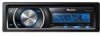
...Tuner Basic Operations 1 23 4 5 6 1 Band indicator 2 5 (stereo) indicator Appears when the selected frequency is being broadcast in stereo. 3 LOC indicator Appears when local seek tuning is on. 4 Preset number indicator 5 Signal level indicator Shows the radio wave strength. 6 Frequency indicator % Select a band Press BAND. # ...or right, you do not operate the list within about 30 seconds, the display automatically returns to select FUNCTION. The selected radio station frequency has been stored in the preset number indicator and then remain lit. Turn to select. The number you release...
...Tuner Basic Operations 1 23 4 5 6 1 Band indicator 2 5 (stereo) indicator Appears when the selected frequency is being broadcast in stereo. 3 LOC indicator Appears when local seek tuning is on. 4 Preset number indicator 5 Signal level indicator Shows the radio wave strength. 6 Frequency indicator % Select a band Press BAND. # ...or right, you do not operate the list within about 30 seconds, the display automatically returns to select FUNCTION. The selected radio station frequency has been stored in the preset number indicator and then remain lit. Turn to select. The number you release...
Owner's Manual
Page 35
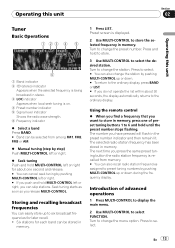
... can be connected to this unit. For details concerning functions, refer to the installation manual. Using the external unit External unit refers to a Pioneer product (such as ones available in the future) that, although incompatible as AUX sources and assigned to AUX1 or AUX2. About AUX1 and AUX2... 05 Other Functions Using the AUX source Up to two auxiliary devices such as the built-in CD player. AUX2 source: When connecting auxiliary equipment using a stereo mini plug cable % Insert the stereo mini plug into the input jack on this unit. Selecting the external unit as the source %...
... can be connected to this unit. For details concerning functions, refer to the installation manual. Using the external unit External unit refers to a Pioneer product (such as ones available in the future) that, although incompatible as AUX sources and assigned to AUX1 or AUX2. About AUX1 and AUX2... 05 Other Functions Using the AUX source Up to two auxiliary devices such as the built-in CD player. AUX2 source: When connecting auxiliary equipment using a stereo mini plug cable % Insert the stereo mini plug into the input jack on this unit. Selecting the external unit as the source %...
Owner's Manual
Page 70
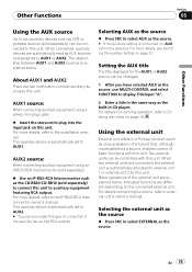
...) (Ver. 7.2 and earlier) WAV signal format Linear PCM & MS ADPCM (Non-compressed) USB Specification USB 2.0 full speed Supply current 500 mA Maximum amount of channels 2 (stereo) MP3 decoding format MPEG-1 & 2 Audio Layer 3 WMA decoding format ......... work) Number of memory 250 GB File system FAT16, FAT32 MP3 decoding format MPEG-1 & 2 Audio Layer...50/63/80/100/125 Hz Slope 18 dB/oct Gain 6 dB to -24 dB Phase Normal/Reverse Bass boost: Gain 12 dB to 0 dB CD player System Compact disc audio system Usable discs Compact disc Signal-to-noise ratio 94 dB (1 kHz) (IHF-A net-
...) (Ver. 7.2 and earlier) WAV signal format Linear PCM & MS ADPCM (Non-compressed) USB Specification USB 2.0 full speed Supply current 500 mA Maximum amount of channels 2 (stereo) MP3 decoding format MPEG-1 & 2 Audio Layer 3 WMA decoding format ......... work) Number of memory 250 GB File system FAT16, FAT32 MP3 decoding format MPEG-1 & 2 Audio Layer...50/63/80/100/125 Hz Slope 18 dB/oct Gain 6 dB to -24 dB Phase Normal/Reverse Bass boost: Gain 12 dB to 0 dB CD player System Compact disc audio system Usable discs Compact disc Signal-to-noise ratio 94 dB (1 kHz) (IHF-A net-
Other Manual
Page 2
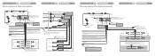
... Connect with Mute function, wire this unit. Note Change the initial setting of any connections. Not used. IP-BUS input (Blue) Multi-CD player IP-BUS cable (sold USB device. Black (chassis ground) Connect to a clean, paint-free metal location. Front speaker ...). Red Connect to the constant 12 V supply terminal. Subwoofer output Fuse (10 A) Dock connector Interface cable AUX jack (3.5 φ) Use a stereo mini plug cable to connect with auxiliary device. 20 cm (7-7/8 in .) Front output Dock connector Interface cable Subwoofer output Fuse (10 A) AUX jack...
... Connect with Mute function, wire this unit. Note Change the initial setting of any connections. Not used. IP-BUS input (Blue) Multi-CD player IP-BUS cable (sold USB device. Black (chassis ground) Connect to a clean, paint-free metal location. Front speaker ...). Red Connect to the constant 12 V supply terminal. Subwoofer output Fuse (10 A) Dock connector Interface cable AUX jack (3.5 φ) Use a stereo mini plug cable to connect with auxiliary device. 20 cm (7-7/8 in .) Front output Dock connector Interface cable Subwoofer output Fuse (10 A) AUX jack...

Other Manual
Page 3
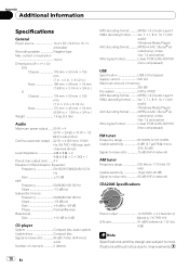
Subwoofer output Fuse (10 A) Dock connector Interface cable AUX jack (3.5 φ) Use a stereo mini plug cable to connect with RCA cables (sold separately) Power amp (sold separately) Power amp (sold separately) Power amp (sold separately) System remote control ...Blue/white Connect to the Audio Mute lead on that this unit's internal amp is turned off. IP-BUS input (Blue) Multi-CD player IP-BUS cable (sold separately). If not, keep the Audio Mute lead free of the power amp or auto-antenna relay control terminal (max...
Subwoofer output Fuse (10 A) Dock connector Interface cable AUX jack (3.5 φ) Use a stereo mini plug cable to connect with RCA cables (sold separately) Power amp (sold separately) Power amp (sold separately) Power amp (sold separately) System remote control ...Blue/white Connect to the Audio Mute lead on that this unit's internal amp is turned off. IP-BUS input (Blue) Multi-CD player IP-BUS cable (sold separately). If not, keep the Audio Mute lead free of the power amp or auto-antenna relay control terminal (max...


