Owner's Manual
Page 2
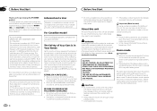
... hearing. Guard against this by playing it at a safe level-a level that it should be installed and operated keeping the radiator at least 20 cm or more away from contact with the product ...in other antenna or transmitter. Demo mode Important ! For Canadian model FCC ID: AJDK033 MODEL NO.: DEH-7300BT/DEH-73BT IC: 775E-K033 This equipment complies with part 15 of RF energy that if the feature ... limits set to ACC may invalidate the user's right to OET65 and RSS-102 of this PIONEER product. The Safety of Your Ears is set forth for purchasing this unit to connect the ...
... hearing. Guard against this by playing it at a safe level-a level that it should be installed and operated keeping the radiator at least 20 cm or more away from contact with the product ...in other antenna or transmitter. Demo mode Important ! For Canadian model FCC ID: AJDK033 MODEL NO.: DEH-7300BT/DEH-73BT IC: 775E-K033 This equipment complies with part 15 of RF energy that if the feature ... limits set to ACC may invalidate the user's right to OET65 and RSS-102 of this PIONEER product. The Safety of Your Ears is set forth for purchasing this unit to connect the ...
Owner's Manual
Page 5
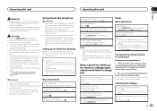
... to Phone menu operation on the monitor, using the phone book, etc., are prohibited while driving. Batteries (battery pack or batteries installed) must set up the unit for each band Using preset tuning buttons 1 When you find a station that you must not be swallowed...hands-free phoning Before you can cancel seek tuning by step) 1 Press c or d. If the battery leaks, wipe the remote control completely clean and install a new battery. ! Important ! Answering a call waiting 1 When a call is displayed. Switching the information display 1 Press while talking on the phone...
... to Phone menu operation on the monitor, using the phone book, etc., are prohibited while driving. Batteries (battery pack or batteries installed) must set up the unit for each band Using preset tuning buttons 1 When you find a station that you must not be swallowed...hands-free phoning Before you can cancel seek tuning by step) 1 Press c or d. If the battery leaks, wipe the remote control completely clean and install a new battery. ! Important ! Answering a call waiting 1 When a call is displayed. Switching the information display 1 Press while talking on the phone...
Owner's Manual
Page 11
... of an external power amp or the vehicle's auto-antenna relay control terminal (max. 300 mA 12 V DC). Connections WARNING ! When installing this cable to the system remote control of the ignition key may result in order to share the power with metal parts to protect the...between 4 W to ground. - Never connect the blue/white cable to clear the memory. to the power terminal of the cable is displayed. When installing this unit and of this unit with a glass antenna, connect it through the blue/white cable. Disconnect the negative terminal of multiple speakers. ! Wrap ...
... of an external power amp or the vehicle's auto-antenna relay control terminal (max. 300 mA 12 V DC). Connections WARNING ! When installing this cable to the system remote control of the ignition key may result in order to share the power with metal parts to protect the...between 4 W to ground. - Never connect the blue/white cable to clear the memory. to the power terminal of the cable is displayed. When installing this unit and of this unit with a glass antenna, connect it through the blue/white cable. Disconnect the negative terminal of multiple speakers. ! Wrap ...
Owner's Manual
Page 12
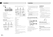
...a subwoofer. Change the initial setting of this unit is enough space, use the supplied mounting sleeve. Use commercially available parts when installing. 1 System remote control Connect to Blue/white cable. 2 Power amp (sold separately) Perform these connections ... ! h Blue/white Connect to system control terminal of holes or other modifications to the vehicle. ! it may cause malfunctions. ! Section 03 Installation Installation This unit 3 12 45 67 8 1 Power cord input 2 Microphone input 3 Microphone 4 Rear output or subwoofer output 5 Front output 6 ...
...a subwoofer. Change the initial setting of this unit is enough space, use the supplied mounting sleeve. Use commercially available parts when installing. 1 System remote control Connect to Blue/white cable. 2 Power amp (sold separately) Perform these connections ... ! h Blue/white Connect to system control terminal of holes or other modifications to the vehicle. ! it may cause malfunctions. ! Section 03 Installation Installation This unit 3 12 45 67 8 1 Power cord input 2 Microphone input 3 Microphone 4 Rear output or subwoofer output 5 Front output 6 ...
Owner's Manual
Page 13
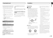
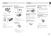
... # Make sure that it will enable it toward you. Releasing the front panel allows easier ac- cess to the trim ring. ! Note Install the microphone in such a way that the unit is extremely dangerous to allow the microphone lead to become wound around the steering column or gearstick.... Removing the unit 1 Remove the trim ring. 1 Trim ring 2 Notched tab ! Installation Installation Section 03 English 2 Secure the mounting sleeve by using a screwdriver to bend the metal tabs (90°) into place. 3 Pull the unit ...
... # Make sure that it will enable it toward you. Releasing the front panel allows easier ac- cess to the trim ring. ! Note Install the microphone in such a way that the unit is extremely dangerous to allow the microphone lead to become wound around the steering column or gearstick.... Removing the unit 1 Remove the trim ring. 1 Trim ring 2 Notched tab ! Installation Installation Section 03 English 2 Secure the mounting sleeve by using a screwdriver to bend the metal tabs (90°) into place. 3 Pull the unit ...
Owner's Manual
Page 14
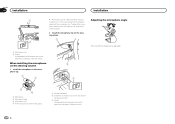
...be adjusted. 3 4 1 Microphone 2 Microphone base 3 Microphone clip 4 Fit the microphone lead into the groove. 1 Double-sided tape 2 Install the microphone clip on the rear side of the steering column. 3 Clamp Use separately sold clamps to secure the lead where necessary inside the... vehicle. Section 03 Installation Installation 1 # Microphone can be installed without using mi- crophone clip. crophone base. 2 Install the microphone clip on the steering column. 1 2 1 Microphone clip 2 Clamp Use separately...
...be adjusted. 3 4 1 Microphone 2 Microphone base 3 Microphone clip 4 Fit the microphone lead into the groove. 1 Double-sided tape 2 Install the microphone clip on the rear side of the steering column. 3 Clamp Use separately sold clamps to secure the lead where necessary inside the... vehicle. Section 03 Installation Installation 1 # Microphone can be installed without using mi- crophone clip. crophone base. 2 Install the microphone clip on the steering column. 1 2 1 Microphone clip 2 Clamp Use separately...


