
Operating Instructions
Page 2
... Instructions" so you very much for purchasing this manual to the customer and explain to the customer how to operate the Plasma Display properly. En Note for damage caused by qualified personnel with enough skill and competence. Notes on Installation Work: This product is installed by mistake in a safe place. Before using your dealer install and set up the product. PIONEER...
... Instructions" so you very much for purchasing this manual to the customer and explain to the customer how to operate the Plasma Display properly. En Note for damage caused by qualified personnel with enough skill and competence. Notes on Installation Work: This product is installed by mistake in a safe place. Before using your dealer install and set up the product. PIONEER...
Operating Instructions
Page 3
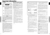
... installation. For correct installation and mounting it and do not produce light or remain lit. Plasma monitor cleaning procedure: 1. Use a wiping cloth (attached) or a soft dry cloth to provide long, trouble-free service. There may be determined by turning the equipment off . Provide adequate space for any phosphor-based display (like a CRT monitor, for a Class B digital device, pursuant to Part 15 of accident, unplug the power cord and...
... installation. For correct installation and mounting it and do not produce light or remain lit. Plasma monitor cleaning procedure: 1. Use a wiping cloth (attached) or a soft dry cloth to provide long, trouble-free service. There may be determined by turning the equipment off . Provide adequate space for any phosphor-based display (like a CRT monitor, for a Class B digital device, pursuant to Part 15 of accident, unplug the power cord and...

Operating Instructions
Page 4
... the manufacturer. 12. Use only with a cart, stand, tripod, bracket, or table specified by applying excessive pull force to operate normally or exhibits a marked change in any heat sources such as to avoid injury from power lines. 19. The power supply cord or the plug has been damaged; or C. or E. Wall Mounting - Power Lines - If an outside antenna is connected to the receiver, be sure the antenna system is damaged...
... the manufacturer. 12. Use only with a cart, stand, tripod, bracket, or table specified by applying excessive pull force to operate normally or exhibits a marked change in any heat sources such as to avoid injury from power lines. 19. The power supply cord or the plug has been damaged; or C. or E. Wall Mounting - Power Lines - If an outside antenna is connected to the receiver, be sure the antenna system is damaged...
Operating Instructions
Page 5
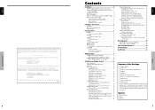
... a video wall 3 Cable Management 3 Caution on when the plasma monitor is installed vertically ... 4 How to use the remote control 4 Battery Installation and Replacement 4 Using the wired remote control mode 4 Operating Range 4 Handling the remote control 4 Part Names and Function 5 Front View 5 Rear View/ Terminal Board 6 Remote Control 7 Basic Operations 8 POWER 8 To turn the unit ON and OFF 8 VOLUME 8 To adjust the sound volume 8 MUTING 8 To mute the sound 8 DISPLAY 8 To check the settings 8 DIGITAL ZOOM 8 AUTO SET UP 8 To adjust the size or quality of the picture...
... a video wall 3 Cable Management 3 Caution on when the plasma monitor is installed vertically ... 4 How to use the remote control 4 Battery Installation and Replacement 4 Using the wired remote control mode 4 Operating Range 4 Handling the remote control 4 Part Names and Function 5 Front View 5 Rear View/ Terminal Board 6 Remote Control 7 Basic Operations 8 POWER 8 To turn the unit ON and OFF 8 VOLUME 8 To adjust the sound volume 8 MUTING 8 To mute the sound 8 DISPLAY 8 To check the settings 8 DIGITAL ZOOM 8 AUTO SET UP 8 To adjust the size or quality of the picture...
Operating Instructions
Page 6
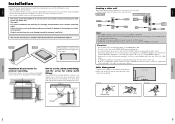
... be turned ON while signals are input to the PC1 terminal if the POWER is poor, do not connect an OUTPUT signal from another plasma display, set the LOOP OUT to ON. • To create a video wall, set the VIDEO WALL menu items properly. • To connect monitors, please use a 1~2m (3.3~6.6 feet) BNC cable (any commercially available distribution amplifier) to connect the split signals to the respective monitor INPUT terminals. • Being used for enclosure mounting...
... be turned ON while signals are input to the PC1 terminal if the POWER is poor, do not connect an OUTPUT signal from another plasma display, set the LOOP OUT to ON. • To create a video wall, set the VIDEO WALL menu items properly. • To connect monitors, please use a 1~2m (3.3~6.6 feet) BNC cable (any commercially available distribution amplifier) to connect the split signals to the respective monitor INPUT terminals. • Being used for enclosure mounting...
Operating Instructions
Page 7
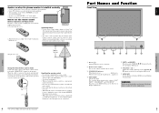
... to set them into a fire. • When using . * Failure to heed the above cautions may not function if the monitor's remote control sensor is exposed to malfunction. When the cable is installed vertically • Use the optional unit. y VOLUME and Adjusts the volume. and RIGHT/+ Functions as the EXIT buttons in the On-Screen Display (OSD) mode. Functions as the CURSOR buttons in the standby mode ... w Remote sensor window Receives the signals...
... to set them into a fire. • When using . * Failure to heed the above cautions may not function if the monitor's remote control sensor is exposed to malfunction. When the cable is installed vertically • Use the optional unit. y VOLUME and Adjusts the volume. and RIGHT/+ Functions as the EXIT buttons in the On-Screen Display (OSD) mode. Functions as the CURSOR buttons in the standby mode ... w Remote sensor window Receives the signals...
Operating Instructions
Page 8
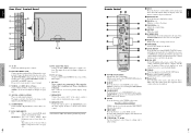
... your Pioneer installation technician. y CURSOR (L / M Use these buttons to select items or settings and to obtain wired remote control. Press this connector without first consulting your speaker's owner's manual. SCREEN SIZE button is selectable. SET Set the ID number in the main menu. When several displays are audio input terminals. SET button. !8 Remote control signal transmitter Transmits the remote control signals. !9 Remote Jack Insert the plug of the remote cable (The 1/8 Stereo Mini cable) here when using the INPUT/ EXIT button on both LEFT and RIGHT channels...
... your Pioneer installation technician. y CURSOR (L / M Use these buttons to select items or settings and to obtain wired remote control. Press this connector without first consulting your speaker's owner's manual. SCREEN SIZE button is selectable. SET Set the ID number in the main menu. When several displays are audio input terminals. SET button. !8 Remote control signal transmitter Transmits the remote control signals. !9 Remote Jack Insert the plug of the remote cable (The 1/8 Stereo Mini cable) here when using the INPUT/ EXIT button on both LEFT and RIGHT channels...

Operating Instructions
Page 9
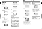
... normal video programs (4:3) with the LMᮤ ᮣ buttons. 2. Press the POWER ON button (on the remote control) to turn on both sides. The monitor's STANDBY/ON indicator turns red and the standby mode is expanded in the horizontal and vertical directions at different ratios. * Use this for approximately three seconds, the menu turns off after a few seconds. 3. The screen changes each time the DISPLAY button is still supplied to display the pointer. ( ) To change the picture...
... normal video programs (4:3) with the LMᮤ ᮣ buttons. 2. Press the POWER ON button (on the remote control) to turn on both sides. The monitor's STANDBY/ON indicator turns red and the standby mode is expanded in the horizontal and vertical directions at different ratios. * Use this for approximately three seconds, the menu turns off after a few seconds. 3. The screen changes each time the DISPLAY button is still supplied to display the pointer. ( ) To change the picture...
Operating Instructions
Page 10
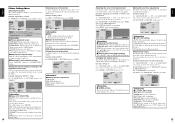
... main menu (1/2), full menu items will not be displayed differently. MAIN MENU 1 / 2 PICTURE SOUND SCREEN OPTION1 ADVANCED OSD NEXT PAGE SEL. The adjustments or the settings that are registered trademarks of Signals Supported" on the remote control to fill the entire screen. 1. Information Ⅵ Language settings ENGLISH ........ English DEUTSCH ....... Press the SCREEN SIZE button on the display output of 31.7 (31.0) kHz are input Select an appropriate setting for RGB SELECT mode referring...
... main menu (1/2), full menu items will not be displayed differently. MAIN MENU 1 / 2 PICTURE SOUND SCREEN OPTION1 ADVANCED OSD NEXT PAGE SEL. The adjustments or the settings that are registered trademarks of Signals Supported" on the remote control to fill the entire screen. 1. Information Ⅵ Language settings ENGLISH ........ English DEUTSCH ....... Press the SCREEN SIZE button on the display output of 31.7 (31.0) kHz are input Select an appropriate setting for RGB SELECT mode referring...

Operating Instructions
Page 11
... (On Screen Display) Controls 12 En English Main menu OPTION2 Sub menu PWR. PURECINEMA LONG LIFE SIDE MASK S1/S2 PICTURE SIZE DVI SET UP Sub menu 2 Sub menu 3 Sub menu 4 OFF@AON OFF@AON ABL AUTO/LOCK 1/LOCK 2/LOCK 3 ORBITER AUTO 1 AUTO 2 MANUAL H-DOT/V-LINE/TIME OFF INVERSE OFF ON WORKING TIME/WAITING TIME WHITE SCREEN WIPER OFF ON WORKING TIME/WAITING TIME/SPEED SOFT FOCUS OFF/1/2/3/4 [email protected]@...A15 AUTO@AOFF OFF@AON PLUG/PLAY PC@ASTB/DVD BLACK LEVEL LOW@AHIGH RESET YES...
... (On Screen Display) Controls 12 En English Main menu OPTION2 Sub menu PWR. PURECINEMA LONG LIFE SIDE MASK S1/S2 PICTURE SIZE DVI SET UP Sub menu 2 Sub menu 3 Sub menu 4 OFF@AON OFF@AON ABL AUTO/LOCK 1/LOCK 2/LOCK 3 ORBITER AUTO 1 AUTO 2 MANUAL H-DOT/V-LINE/TIME OFF INVERSE OFF ON WORKING TIME/WAITING TIME WHITE SCREEN WIPER OFF ON WORKING TIME/WAITING TIME/SPEED SOFT FOCUS OFF/1/2/3/4 [email protected]@...A15 AUTO@AOFF OFF@AON PLUG/PLAY PC@ASTB/DVD BLACK LEVEL LOW@AHIGH RESET YES...
Operating Instructions
Page 12
... OSD (On Screen Display) Controls Information Ⅵ Types of "PICTURE" menu, select "HIGH". This mode provides pictures with distinct differences between light and dark sections. On "COLOR TEMP." HIGH R.HIGH G.HIGH B.HIGH R.LOW G.LOW B.LOW RESET : OFF R.HIGH 70 SEL. Making the Low Tone adjustments This feature allows more detailed tone to the factory default values. Example: Setting "2" Set "ADVANCED OSD" to set to DEFAULT. RED Y M GREEN C Y BLUE M C YELLOW G R MAGENTA...
... OSD (On Screen Display) Controls Information Ⅵ Types of "PICTURE" menu, select "HIGH". This mode provides pictures with distinct differences between light and dark sections. On "COLOR TEMP." HIGH R.HIGH G.HIGH B.HIGH R.LOW G.LOW B.LOW RESET : OFF R.HIGH 70 SEL. Making the Low Tone adjustments This feature allows more detailed tone to the factory default values. Example: Setting "2" Set "ADVANCED OSD" to set to DEFAULT. RED Y M GREEN C Y BLUE M C YELLOW G R MAGENTA...
Operating Instructions
Page 13
... "OFF" SCREEN SCREEN SIZE : FULL V. Information Ⅵ SOUND settings menu BASS: Controls the level of "SOUND" menu, adjust the bass. Not available for PC2/ COMPONENT2 input. But, these 8 modes must be corrected. TREBLE: Controls the level of the menu, the display format (horizontal or vertical) etc. ADJ. SIZE AUTO PICTURE : OFF PHASE CLOCK V.POSITION +64 SEL. V.SIZE: Adjusts the vertical size of the image. (Except for WIDE mode) H.SIZE: Adjusts the horizontal size of input signals as follows each time OSD is...
... "OFF" SCREEN SCREEN SIZE : FULL V. Information Ⅵ SOUND settings menu BASS: Controls the level of "SOUND" menu, adjust the bass. Not available for PC2/ COMPONENT2 input. But, these 8 modes must be corrected. TREBLE: Controls the level of the menu, the display format (horizontal or vertical) etc. ADJ. SIZE AUTO PICTURE : OFF PHASE CLOCK V.POSITION +64 SEL. V.SIZE: Adjusts the vertical size of the image. (Except for WIDE mode) H.SIZE: Adjusts the horizontal size of input signals as follows each time OSD is...

Operating Instructions
Page 14
... the monitor's power consumption if no input signal is present, skip that signal. * "SETTING NOW" will be displayed. MENU OK EXIT RETURN ALL RESET SETTING NOW When the "SETTING NOW" screen disappears, then all the settings (PICTURE, SOUND, SCREEN, OPTION1~3, etc) to set RGB SELECT to reduce burn-in the main menu (1/ 2), then perform the following operations. MGT. : ON PURECINEMA : ON LONG LIFE SIDE MASK : 3 S1/S2 : OFF PICTURE SIZE : ON DVI SET-UP...
... the monitor's power consumption if no input signal is present, skip that signal. * "SETTING NOW" will be displayed. MENU OK EXIT RETURN ALL RESET SETTING NOW When the "SETTING NOW" screen disappears, then all the settings (PICTURE, SOUND, SCREEN, OPTION1~3, etc) to set RGB SELECT to reduce burn-in the main menu (1/ 2), then perform the following operations. MGT. : ON PURECINEMA : ON LONG LIFE SIDE MASK : 3 S1/S2 : OFF PICTURE SIZE : ON DVI SET-UP...
Operating Instructions
Page 15
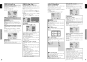
...; ORBITER settings OFF: Orbiter mode does not function. This is the default setting when a Video or a COMPONENT signal is input, the AUTO1 and 2 functions will affect only the moving picture and will not make the screen smaller or bigger. MANUAL: User can set the time by pressing the MENU/SET button while "ON" is displayed alternately between movement. ADJ. WHITE: The entire screen turns white. Setting the time for "INVERSE/WHITE". SEL. ADJ. Set to...
...; ORBITER settings OFF: Orbiter mode does not function. This is the default setting when a Video or a COMPONENT signal is input, the AUTO1 and 2 functions will affect only the moving picture and will not make the screen smaller or bigger. MANUAL: User can set the time by pressing the MENU/SET button while "ON" is displayed alternately between movement. ADJ. WHITE: The entire screen turns white. Setting the time for "INVERSE/WHITE". SEL. ADJ. Set to...

Operating Instructions
Page 16
.... ADJ. DVI SET-UP PLUG/PLAY : BLACK LEVEL : STB/DVD HIGH Information Ⅵ PLUG/PLAY settings PC: When connected to the S1/S2 video signal. BLACK LEVEL is set to AUTO. Change "HIGH" into "LOW" if the black level appears gray. 22 En SEL. EXIT RETURN Select "SET", then press the MENU/SET button. PROGRAM TIMER This sets the day and time at which the power will be switched ON/OFF as well as the input mode. The "PROGRAM TIMER" screen appears...
.... ADJ. DVI SET-UP PLUG/PLAY : BLACK LEVEL : STB/DVD HIGH Information Ⅵ PLUG/PLAY settings PC: When connected to the S1/S2 video signal. BLACK LEVEL is set to AUTO. Change "HIGH" into "LOW" if the black level appears gray. 22 En SEL. EXIT RETURN Select "SET", then press the MENU/SET button. PROGRAM TIMER This sets the day and time at which the power will be switched ON/OFF as well as the input mode. The "PROGRAM TIMER" screen appears...
Operating Instructions
Page 17
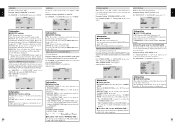
... remote control Example: Setting "2" Press the ID NO. VIDEO WALL DIVIDER : 4 POSITION DISP. VIDEO WALL POSITION POSITION NO. 4 OSD (On Screen Display) Controls ADJ. ON DELAY : OFF ABL LINK : OFF REPEAT TIMER : OFF SEL. English Setting the power on mode This function sets the input mode at the time the power switched on... VIDEO1, 2, 3: VIDEO input mode. OFF: Enables the buttons on the front panel. * Even when the KEY LOCK is being turned off. Ⅵ To connect another display...
... remote control Example: Setting "2" Press the ID NO. VIDEO WALL DIVIDER : 4 POSITION DISP. VIDEO WALL POSITION POSITION NO. 4 OSD (On Screen Display) Controls ADJ. ON DELAY : OFF ABL LINK : OFF REPEAT TIMER : OFF SEL. English Setting the power on mode This function sets the input mode at the time the power switched on... VIDEO1, 2, 3: VIDEO input mode. OFF: Enables the buttons on the front panel. * Even when the KEY LOCK is being turned off. Ⅵ To connect another display...

Operating Instructions
Page 18
... "SCREEN" screen appears. SIZE AUTO PICTURE : OFF PHASE CLOCK V.POSITION +64 SEL. Turn on delay. On "AUTO ID" of "SCREEN" menu, adjust the position. ON DELAY (Power on delay) Use this won't be operated unless the IR REMOTE is selected. Note: The remote control can be set only when a 2×2 or 3×3 video wall is set the DIVIDER (at the same time. (Only for advanced users. Adjust the items. REPEAT TIMER 1 DIVIDER : 1 SOURCE : VIDEO1 WORK TIME...
... "SCREEN" screen appears. SIZE AUTO PICTURE : OFF PHASE CLOCK V.POSITION +64 SEL. Turn on delay. On "AUTO ID" of "SCREEN" menu, adjust the position. ON DELAY (Power on delay) Use this won't be operated unless the IR REMOTE is selected. Note: The remote control can be set only when a 2×2 or 3×3 video wall is set the DIVIDER (at the same time. (Only for advanced users. Adjust the items. REPEAT TIMER 1 DIVIDER : 1 SOURCE : VIDEO1 WORK TIME...

Operating Instructions
Page 19
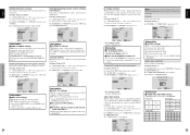
... 11 12 13 14 15 Signal (Analog) Red Green or sync-on-green Blue No connection Ground Red ground Green ground Blue ground No connection Sync signal ground No connection Bi-directional DATA (SDA) Horizontal sync or Composite sync Vertical sync Data clock DVI-D 24-pin connector (Digital) The unit is used mainly in your current country. FREQUENCY : 60.0Hz H. Pin Assignments 29 En English Color System Settings Menu Setting the video signal format Use these operations to set accordingly.
... 11 12 13 14 15 Signal (Analog) Red Green or sync-on-green Blue No connection Ground Red ground Green ground Blue ground No connection Sync signal ground No connection Bi-directional DATA (SDA) Horizontal sync or Composite sync Vertical sync Data clock DVI-D 24-pin connector (Digital) The unit is used mainly in your current country. FREQUENCY : 60.0Hz H. Pin Assignments 29 En English Color System Settings Menu Setting the video signal format Use these operations to set accordingly.
Operating Instructions
Page 20
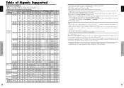
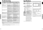
... 59 61.8 C Sync C Sync - - - - If this occurs, please set the RGB mode prepared for the input signals listed in the table above , you may have to adjust the position and size of the picture or the fine picture because of errors in the original resolution. • When the screen size is FULL, each signal is converted to 60Hz. Table of Signals Supported English 30 En Table of Signals Supported Supported resolution • When the screen size is 4:3, each signal...
... 59 61.8 C Sync C Sync - - - - If this occurs, please set the RGB mode prepared for the input signals listed in the table above , you may have to adjust the position and size of the picture or the fine picture because of errors in the original resolution. • When the screen size is FULL, each signal is converted to 60Hz. Table of Signals Supported English 30 En Table of Signals Supported Supported resolution • When the screen size is 4:3, each signal...
Operating Instructions
Page 21
... the remote cable from the source equipment (DVD, Set-top box, etc...). SET button, or set the ID number to ALL. • Plug the monitor's power cord into a power outlet. • Press the power button on the monitor to prevent over heating. • Are the image and sound normal? • If there are no sound is produced. No sound or picture is noisy. Poor picture with VIDEO signal input. Nothing appears on the remote control and adjust properly. • Set to...
... the remote cable from the source equipment (DVD, Set-top box, etc...). SET button, or set the ID number to ALL. • Plug the monitor's power cord into a power outlet. • Press the power button on the monitor to prevent over heating. • Are the image and sound normal? • If there are no sound is produced. No sound or picture is noisy. Poor picture with VIDEO signal input. Nothing appears on the remote control and adjust properly. • Set to...


