Operating Instructions
Page 3
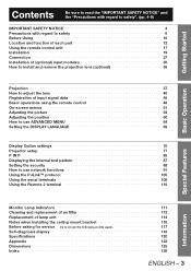
... Using 10 Location and function of each part 12 Using the remote control unit 17 Installation 19 Connection 27 Installation of (optional) input modules 30 How to install and remove the projection lens (optional 36 Projection 37 How to adjust the lens 40 Registration of input signal data 45 Basic operations using the remote control 48 On-screen menus 51 Adjusting the picture 54 Adjusting the position 60 How to use ADVANCED MENU 64 Setting the DISPLAY LANGUAGE 69 Display Option settings 70 Projector setup 77...
... Using 10 Location and function of each part 12 Using the remote control unit 17 Installation 19 Connection 27 Installation of (optional) input modules 30 How to install and remove the projection lens (optional 36 Projection 37 How to adjust the lens 40 Registration of input signal data 45 Basic operations using the remote control 48 On-screen menus 51 Adjusting the picture 54 Adjusting the position 60 How to use ADVANCED MENU 64 Setting the DISPLAY LANGUAGE 69 Display Option settings 70 Projector setup 77...
Operating Instructions
Page 11
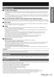
... high-contrast and clear images if outside light or the illumination interferes the screen surface. ENGLISH - 11 Draw window curtains or blinds, turn off . • Do not clean the lens surface with bare hand. Keep your hands away from the exhaust port depending on the screen. Cover the lens with a loud sound or end its affiliate companies would never directly inquire about your password. • Use a network...
... high-contrast and clear images if outside light or the illumination interferes the screen surface. ENGLISH - 11 Draw window curtains or blinds, turn off . • Do not clean the lens surface with bare hand. Keep your hands away from the exhaust port depending on the screen. Cover the lens with a loud sound or end its affiliate companies would never directly inquire about your password. • Use a network...

Operating Instructions
Page 14
... the lens cowling, pulling it forward to remove. s Lamp unit cover p. 115) This hinged panel swings down for "Error Condition". 5 Temperature monitor (TEMP p. 111) These LEDs illuminate and flash to green when the POWER ON button of the remote control or the main unit is being cleaned. It turns to indicate lamp warmup intervals, abnormal internal temperatures, or cooling fan errors. 6 Power indicator lamp p. 37) The lamp lights in red when the MAIN POWER switch is a problem with the air filter. q Remote control receiver window (bottom...
... the lens cowling, pulling it forward to remove. s Lamp unit cover p. 115) This hinged panel swings down for "Error Condition". 5 Temperature monitor (TEMP p. 111) These LEDs illuminate and flash to green when the POWER ON button of the remote control or the main unit is being cleaned. It turns to indicate lamp warmup intervals, abnormal internal temperatures, or cooling fan errors. 6 Power indicator lamp p. 37) The lamp lights in red when the MAIN POWER switch is a problem with the air filter. q Remote control receiver window (bottom...

Operating Instructions
Page 28
... other problems may be distorted. Connection (continued) Example of connecting with VIDEO devices Control PC Control PC Control PC Video deck (TBC built-in) IN OUT REMOTE 1 REMOTE 2 IN RS-232C IN RS-422 IN SERIAL RS-422 OUT LAN IN OUT VIDEO S-VIDEO IN R/PR G/Y SYNC/HD RGB 1 IN B/PB VD RGB 2 IN DVI-D IN Red (connected to PR terminal) Blue (connected to PB terminal) Green (connected to Y terminal) Color monitor Video...
... other problems may be distorted. Connection (continued) Example of connecting with VIDEO devices Control PC Control PC Control PC Video deck (TBC built-in) IN OUT REMOTE 1 REMOTE 2 IN RS-232C IN RS-422 IN SERIAL RS-422 OUT LAN IN OUT VIDEO S-VIDEO IN R/PR G/Y SYNC/HD RGB 1 IN B/PB VD RGB 2 IN DVI-D IN Red (connected to PR terminal) Blue (connected to PB terminal) Green (connected to Y terminal) Color monitor Video...
Operating Instructions
Page 37
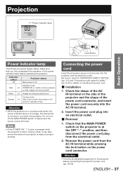
... electrical outlet. „ Removal 1. Indicator status Off Projector status Main power is at this time. Attention • While the projector is running to project pictures. Projection Power indicator lamp Basic Operation FILTER CLEANING OPEN CLOSE Lock Button Power indicator lamp This shows the power supply status. Note • If the POWER ON " | " button is pressed while the projector is still in cooling mode (when the power indicator lamp is lit orange), the internal fan is in cooling mode, it may take some time before connecting the projector's power cord. (pp. 28...
... electrical outlet. „ Removal 1. Indicator status Off Projector status Main power is at this time. Attention • While the projector is running to project pictures. Projection Power indicator lamp Basic Operation FILTER CLEANING OPEN CLOSE Lock Button Power indicator lamp This shows the power supply status. Note • If the POWER ON " | " button is pressed while the projector is still in cooling mode (when the power indicator lamp is lit orange), the internal fan is in cooling mode, it may take some time before connecting the projector's power cord. (pp. 28...
Operating Instructions
Page 41
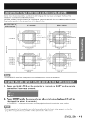
... hold LENS on the projector's controls or SHIFT on the remote control for the projection lens is the lens position when the lens is being replaced or when the projector is being displayed. (It will move the lens beyond the bounds of the projector. This limitation is not the optical center of projection lens PT-D12000U PT-DZ12000U 0.15V 0.50V Projected 0.15V screen height, V0.15V 0.12V 0.40V 0.12V screen height, V Projected Basic Operation...
... hold LENS on the projector's controls or SHIFT on the remote control for the projection lens is the lens position when the lens is being replaced or when the projector is being displayed. (It will move the lens beyond the bounds of the projector. This limitation is not the optical center of projection lens PT-D12000U PT-DZ12000U 0.15V 0.50V Projected 0.15V screen height, V0.15V 0.12V 0.40V 0.12V screen height, V Projected Basic Operation...

Operating Instructions
Page 42
... screen side) Lens bracket a Locking screw c b (Adjust the focus adjustment screws a, b and c after installing the lens.) Figure 3 : Cross section view of lens orientation Projection lens Image formation surface (DMD image plane) Screen surface versus focal point „ Procedure for adjusting the focus balance (tilt compensation in the lens mount) z Three focus adjustment screws on the lens mount may be tilted up and down, and three more screws lock down the adjustment. Figure 1: Illustration of influence of the lens mount Lens tilt direction (when adjustment screws turned...
... screen side) Lens bracket a Locking screw c b (Adjust the focus adjustment screws a, b and c after installing the lens.) Figure 3 : Cross section view of lens orientation Projection lens Image formation surface (DMD image plane) Screen surface versus focal point „ Procedure for adjusting the focus balance (tilt compensation in the lens mount) z Three focus adjustment screws on the lens mount may be tilted up and down, and three more screws lock down the adjustment. Figure 1: Illustration of influence of the lens mount Lens tilt direction (when adjustment screws turned...
Operating Instructions
Page 49
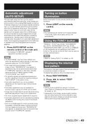
... signals consisting of the set. In this case, manually adjust the "CLOCK PHASE". • If an image with a bright white frame at the outermost periphery containing characters etc. Press AUTO SETUP on -screen menu. This is not a malfunction. • For every supplied signal, adjustment is required. • Automatic adjustment can be canceled by using an on the remote control or the main unit. • A message "COMPLETE" appears if adjustment...
... signals consisting of the set. In this case, manually adjust the "CLOCK PHASE". • If an image with a bright white frame at the outermost periphery containing characters etc. Press AUTO SETUP on -screen menu. This is not a malfunction. • For every supplied signal, adjustment is required. • Automatic adjustment can be canceled by using an on the remote control or the main unit. • A message "COMPLETE" appears if adjustment...

Operating Instructions
Page 56
...; to the factory default setting. • The color temperature cannot be displayed. Press ▲▼ to project the input signal when adjusting the color temperature. WHITE BALANCE HIGH RED 255 GREEN 255 8. GREEN Press ◄ button. BLUE Press ► button. Deepens green. Be sure to select "WHITE BALANCE HIGH" or "WHITE BALANCE LOW". 7. GAMMA DEFAULT CHANGE 3. GAMMA SYSTEM DAYLIGHT VIEW SHARPNESS DEFAULT OFF 0 2. Press ◄► or ENTER. • The "SYSTEM DAYLIGHT VIEW" individual adjustment screen will change as follows each time ◄...
...; to the factory default setting. • The color temperature cannot be displayed. Press ▲▼ to project the input signal when adjusting the color temperature. WHITE BALANCE HIGH RED 255 GREEN 255 8. GREEN Press ◄ button. BLUE Press ► button. Deepens green. Be sure to select "WHITE BALANCE HIGH" or "WHITE BALANCE LOW". 7. GAMMA DEFAULT CHANGE 3. GAMMA SYSTEM DAYLIGHT VIEW SHARPNESS DEFAULT OFF 0 2. Press ◄► or ENTER. • The "SYSTEM DAYLIGHT VIEW" individual adjustment screen will change as follows each time ◄...
Operating Instructions
Page 64
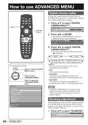
... image lies slightly offscreen. 1. Press ▲▼ to display the MAIN MENU screen. DIGITAL CINEMA REALITY BLANKING INPUT RESOLUTION AUTO ADVANCED MENU DIGITAL CINEMA REALITY BLANKING AUTO 2. DIGITAL CINEMA REALITY AUTO CHANGE 3. Press ◄► or ENTER. • The "DIGITAL CINEMA REALITY" individual adjustment screen will change as follows each time ◄► is pressed. Press to select "ADVANCED MENU". MAIN MENU PICTURE POSITION ADVANCED MENU DISPLAY LANGUAGE DISPLAY OPTION PROJECTOR SETUP P IN P TEST PATTERN SIGNAL LIST SECURITY NETWORK MENU...
... image lies slightly offscreen. 1. Press ▲▼ to display the MAIN MENU screen. DIGITAL CINEMA REALITY BLANKING INPUT RESOLUTION AUTO ADVANCED MENU DIGITAL CINEMA REALITY BLANKING AUTO 2. DIGITAL CINEMA REALITY AUTO CHANGE 3. Press ◄► or ENTER. • The "DIGITAL CINEMA REALITY" individual adjustment screen will change as follows each time ◄► is pressed. Press to select "ADVANCED MENU". MAIN MENU PICTURE POSITION ADVANCED MENU DISPLAY LANGUAGE DISPLAY OPTION PROJECTOR SETUP P IN P TEST PATTERN SIGNAL LIST SECURITY NETWORK MENU...

Operating Instructions
Page 73
... instruction manual of a still image system is selected, auto setup will change as follows each time ◄► is pressed. 0-255:PC 16-235 • 0-255:PC: Select this when, for example, an external device (PC, etc.) is connected via the HDMI terminal output using a conversion cable. If "User" is pressed. Note • The optimal setting differs depending on the output setting of signal source into "DISPLAY DOTS...
... instruction manual of a still image system is selected, auto setup will change as follows each time ◄► is pressed. 0-255:PC 16-235 • 0-255:PC: Select this when, for example, an external device (PC, etc.) is connected via the HDMI terminal output using a conversion cable. If "User" is pressed. Note • The optimal setting differs depending on the output setting of signal source into "DISPLAY DOTS...

Operating Instructions
Page 75
... screen) 7 (Top right of the screen) 6 (Bottom center of the screen) z OSD DESIGN This sets the color of the input signals. z SDI SIGNAL LEVEL Set to match the dynamic range (black-to-white) of the on-screen display (OSD). 1 2 6 3 5 4 • 1: Displayed in yellow. • 2: Displayed in blue. • 3: Displayed in white. • 4: Displayed in green. • 5: Displayed in pink. • 6: Displayed in brown. This is pressed. 64-940 4-1019 • 64-940: Default...
... screen) 7 (Top right of the screen) 6 (Bottom center of the screen) z OSD DESIGN This sets the color of the input signals. z SDI SIGNAL LEVEL Set to match the dynamic range (black-to-white) of the on-screen display (OSD). 1 2 6 3 5 4 • 1: Displayed in yellow. • 2: Displayed in blue. • 3: Displayed in white. • 4: Displayed in green. • 5: Displayed in pink. • 6: Displayed in brown. This is pressed. 64-940 4-1019 • 64-940: Default...

Operating Instructions
Page 82
... hours elapsed 10 hours elapsed Setting time Setting time Setting time Automatic cleaning (No cleaning) Automatic cleaning Time reset • When projection starts (when the power is pressed. Example: If the setting time is 7:00 and forced cleaning is carried out at 9:00, then automatic cleaning will be cleaned when air filter cleaning is reached. Auto power off The projector can select the automatic cleaning time ("TIME") and also force cleaning to automatically enter the standby state if no signal is in use the...
... hours elapsed 10 hours elapsed Setting time Setting time Setting time Automatic cleaning (No cleaning) Automatic cleaning Time reset • When projection starts (when the power is pressed. Example: If the setting time is 7:00 and forced cleaning is carried out at 9:00, then automatic cleaning will be cleaned when air filter cleaning is reached. Auto power off The projector can select the automatic cleaning time ("TIME") and also force cleaning to automatically enter the standby state if no signal is in use the...
Operating Instructions
Page 84
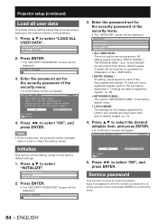
... ALL USER DATA LOAD ALL USER DATA INITIALIZE 2. Note • If this is executed, the projector enters a standby state in "Clearing the data of the security menu. • The "INITIALIZE" screen will appear. Press ENTER. • The "SECURITY PASSWORD" screen will appear. INITIALIZE ALL USER DATA ENTRY SIGNAL NETWORK/E-MAIL LOGO IMAGE • ALL USER DATA: This is used by service personnel. PROGRESS OK CANCEL CHANGE ENTER SET 5. ENGLISH Projector setup (continued) Load all user data...
... ALL USER DATA LOAD ALL USER DATA INITIALIZE 2. Note • If this is executed, the projector enters a standby state in "Clearing the data of the security menu. • The "INITIALIZE" screen will appear. Press ENTER. • The "SECURITY PASSWORD" screen will appear. INITIALIZE ALL USER DATA ENTRY SIGNAL NETWORK/E-MAIL LOGO IMAGE • ALL USER DATA: This is used by service personnel. PROGRESS OK CANCEL CHANGE ENTER SET 5. ENGLISH Projector setup (continued) Load all user data...

Operating Instructions
Page 111
... lamp Lamp indication Information Check point Remedial measure Warm-up status TEMP monitor Lighting in red High temperature inside (Standby condition) • Did you notice a "REPLACE THE LAMP" message on the screen when turning on page 39 and consult the distributor. Lighting in red Indicates the time for fluctuation (or drop) in the source voltage. • Turn off the MAIN POWER switch using the procedure on page 39 and clean the air filter. (pp. 112-113) Blinking in red (3 times) Cooling fan...
... lamp Lamp indication Information Check point Remedial measure Warm-up status TEMP monitor Lighting in red High temperature inside (Standby condition) • Did you notice a "REPLACE THE LAMP" message on the screen when turning on page 39 and consult the distributor. Lighting in red Indicates the time for fluctuation (or drop) in the source voltage. • Turn off the MAIN POWER switch using the procedure on page 39 and clean the air filter. (pp. 112-113) Blinking in red (3 times) Cooling fan...
Operating Instructions
Page 114
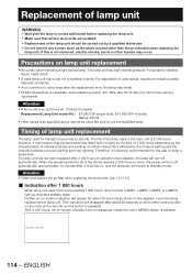
... time of 2 000 hours depending on -screen indication will turn off automatically approximately 10 minutes after 2 000 hours of operation have reached 1 800 hours, lamp monitor (LAMP1, LAMP2, LAMP3, or LAMP4) light up including standby state. If this is an optional part. Precautions on , and the projector will not disappear unless the menu (MENU) button is turned on lamp unit replacement • Be careful when handling a light source lamp. If improperly handled, failure...
... time of 2 000 hours depending on -screen indication will turn off automatically approximately 10 minutes after 2 000 hours of operation have reached 1 800 hours, lamp monitor (LAMP1, LAMP2, LAMP3, or LAMP4) light up including standby state. If this is an optional part. Precautions on , and the projector will not disappear unless the menu (MENU) button is turned on lamp unit replacement • Be careful when handling a light source lamp. If improperly handled, failure...

Operating Instructions
Page 117
... power supply live at the receptacle? • Is the temperature monitor (TEMP) lamp on the projector front lighting or blinking? • Is the lamp monitor (LAMP) lamp on the projector front lighting or blinking? • Is the lamp unit cover completely attached? • Was operation of ID setting made in a correctly way? • Are all four lamp units installed? • Is the screen image input connected in a correct manner? • Are the settings of switching input signals correct...
... power supply live at the receptacle? • Is the temperature monitor (TEMP) lamp on the projector front lighting or blinking? • Is the lamp monitor (LAMP) lamp on the projector front lighting or blinking? • Is the lamp unit cover completely attached? • Was operation of ID setting made in a correctly way? • Are all four lamp units installed? • Is the screen image input connected in a correct manner? • Are the settings of switching input signals correct...
Operating Instructions
Page 120
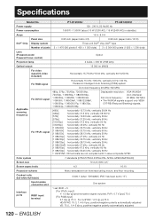
... SYNC. Specifications Model No. Color system 7 standards (NTSC/NTSC4.43/PAL/PAL-N/PAL-M/SECAM/PAL60) Screen size 70 inch-600 inch*1 Screen aspect ratio 4:3 16:10 Projection scheme Menu-selectable from front/rear/ceiling mount, and floor mounting Contrast ratio (full white/full black) 5 000:1 (when "DYNAMIC IRIS" has been set to "3") Interface ports Input module connection slot RGB1 input terminal One system 1 set, BNC × 5 [For YPBPR input] Y: 1.0 V[p-p] synchronization signal...
... SYNC. Specifications Model No. Color system 7 standards (NTSC/NTSC4.43/PAL/PAL-N/PAL-M/SECAM/PAL60) Screen size 70 inch-600 inch*1 Screen aspect ratio 4:3 16:10 Projection scheme Menu-selectable from front/rear/ceiling mount, and floor mounting Contrast ratio (full white/full black) 5 000:1 (when "DYNAMIC IRIS" has been set to "3") Interface ports Input module connection slot RGB1 input terminal One system 1 set, BNC × 5 [For YPBPR input] Y: 1.0 V[p-p] synchronization signal...
Operating Instructions
Page 121
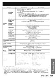
... m), the ambient temperature is used in high altitude mode) when using the projector with 3-value direct SYNC. Video input/ output terminal 1 set BNC 1.0 V [p-p] 75 Ω (Active through for Video output) S-video input terminal 1 set Mini DIN 4p Y 1.0 V [p-p] C 0.286 V [p-p] 75 Ω Compliant with S1 signals Interface ports DVI-D input terminal 1 set DVI 1.0 compliant HDCP (Single link only) compatible LAN terminal 1 set (Used for network connection) 10BASE-T/100BASE-TX PJLink™ compatible Serial input terminal 2 sets D-sub 9-pin...
... m), the ambient temperature is used in high altitude mode) when using the projector with 3-value direct SYNC. Video input/ output terminal 1 set BNC 1.0 V [p-p] 75 Ω (Active through for Video output) S-video input terminal 1 set Mini DIN 4p Y 1.0 V [p-p] C 0.286 V [p-p] 75 Ω Compliant with S1 signals Interface ports DVI-D input terminal 1 set DVI 1.0 compliant HDCP (Single link only) compatible LAN terminal 1 set (Used for network connection) 10BASE-T/100BASE-TX PJLink™ compatible Serial input terminal 2 sets D-sub 9-pin...
Operating Instructions
Page 126
... 62 Adjusting the input resolution 65 Adjusting the zoom ratio 62 Adjusting Tint 55 Air filter cleaning 81 Altitude Mode 78 Automatic adjustment 49 Auto power off 82 AUX DVI IN 74 AUX SDI IN 74 B Back Color 75 Basic operations on menu screen 53 Before asking for service 117 Blanking adjustment 64 C Changing the security password 89 Changing the text 89 Cleaning and replacement of air filter 112 Clock phase adjustment 62 Compatible Signals 122 Connecting the power cord 37 Connecting...
... 62 Adjusting the input resolution 65 Adjusting the zoom ratio 62 Adjusting Tint 55 Air filter cleaning 81 Altitude Mode 78 Automatic adjustment 49 Auto power off 82 AUX DVI IN 74 AUX SDI IN 74 B Back Color 75 Basic operations on menu screen 53 Before asking for service 117 Blanking adjustment 64 C Changing the security password 89 Changing the text 89 Cleaning and replacement of air filter 112 Clock phase adjustment 62 Compatible Signals 122 Connecting the power cord 37 Connecting...


