Operating Instructions
Page 3
... install and remove the projection lens (optional 33 Projection ...34 How to adjust the lens ...37 Automatic adjustment (AUTO SETUP 39 Registration of input signal data 40 Basic operations using the remote control 43 On-screen menus ...46 Adjusting the picture...49 Adjusting the position...56 How to use network function 84 Using the PJLink™ protocol 98 Setting the security ...99 Using the serial terminals 102 Using the Remote 2 terminal 106 Special Features Information Indication of monitor lamp 107 Cleaning and replacement...
... install and remove the projection lens (optional 33 Projection ...34 How to adjust the lens ...37 Automatic adjustment (AUTO SETUP 39 Registration of input signal data 40 Basic operations using the remote control 43 On-screen menus ...46 Adjusting the picture...49 Adjusting the position...56 How to use network function 84 Using the PJLink™ protocol 98 Setting the security ...99 Using the serial terminals 102 Using the Remote 2 terminal 106 Special Features Information Indication of monitor lamp 107 Cleaning and replacement...

Operating Instructions
Page 11
.... Draw window curtains or blinds, turn off the lightings near the screen or take other nearby equipment. ■ Do not touch the surface of this product. Cover the lens with high internal pressure is used . ■ Screen If the screen has stains, flaws or discoloration, clear images cannot be magnified and projected on the screen. ■ Lamp A mercury lamp with the supplied lens cap when the projector is used...
.... Draw window curtains or blinds, turn off the lightings near the screen or take other nearby equipment. ■ Do not touch the surface of this product. Cover the lens with high internal pressure is used . ■ Screen If the screen has stains, flaws or discoloration, clear images cannot be magnified and projected on the screen. ■ Lamp A mercury lamp with the supplied lens cap when the projector is used...

Operating Instructions
Page 12
... projector is being used by service personnel for entering passwords when password entry is needed. . The light goes off the on the menu screen, change the RGB1, RGB2, DVI-D, VIDEO, S-VIDEO and AUX (module input) input ports. ( MENU button pp. 46, 48) Displays and clears the Main Menu. Also use them to send information about 10 seconds after you stop remote control operation. 0 AUTO SET UP button p. 44) Pressing this button while projecting an image automatically corrects the picture...
... projector is being used by service personnel for entering passwords when password entry is needed. . The light goes off the on the menu screen, change the RGB1, RGB2, DVI-D, VIDEO, S-VIDEO and AUX (module input) input ports. ( MENU button pp. 46, 48) Displays and clears the Main Menu. Also use them to send information about 10 seconds after you stop remote control operation. 0 AUTO SET UP button p. 44) Pressing this button while projecting an image automatically corrects the picture...

Operating Instructions
Page 14
...Temperature monitor (TEMP p. 107) Lighting or blinking of this hook port. - ENGLISH Location and function of each part (continued) Projector Main Unit ■ Front ■ Rear # $ % &( ) * 2 * + -. / 0 1 34 56 # Projectin lens cover p. 33) $ Projection lens (optional) Lens for the projection lens (optional). / Air filter p. 108) 0 Air filter cleaning monitor pp. 80-81, 108) This blinks blue while the air filter is being cleaned. Adjustable feet p. 20) Use these feet to " l " (on the screen. % Remote control receiver window (front) .. (p. 17) This window receives the signal...
...Temperature monitor (TEMP p. 107) Lighting or blinking of this hook port. - ENGLISH Location and function of each part (continued) Projector Main Unit ■ Front ■ Rear # $ % &( ) * 2 * + -. / 0 1 34 56 # Projectin lens cover p. 33) $ Projection lens (optional) Lens for the projection lens (optional). / Air filter p. 108) 0 Air filter cleaning monitor pp. 80-81, 108) This blinks blue while the air filter is being cleaned. Adjustable feet p. 20) Use these feet to " l " (on the screen. % Remote control receiver window (front) .. (p. 17) This window receives the signal...

Operating Instructions
Page 15
... projection mode with the MAIN POWER switch of the projector at least 3 seconds while the on the menu screen, change the VIDEO, S-VIDEO, RGB1, RGB2, DVI-D and AUX (module input) input ports. / AUTO SETUP button p. 44) Pressing this receptacle. ENGLISH - 15 Getting Started ■ Side Connection terminals (p. 16) Controls ■ Controls &( ) * +- # $% . /0 1 2 # AC IN terminal p. 34) Connect the supplied line power cord into this button while projecting an image automatically corrects the picture positioning on the screen. It can be displayed...
... projection mode with the MAIN POWER switch of the projector at least 3 seconds while the on the menu screen, change the VIDEO, S-VIDEO, RGB1, RGB2, DVI-D and AUX (module input) input ports. / AUTO SETUP button p. 44) Pressing this receptacle. ENGLISH - 15 Getting Started ■ Side Connection terminals (p. 16) Controls ■ Controls &( ) * +- # $% . /0 1 2 # AC IN terminal p. 34) Connect the supplied line power cord into this button while projecting an image automatically corrects the picture positioning on the screen. It can be displayed...

Operating Instructions
Page 25
... Red (connected to PR terminal) Blue (connected to PB terminal) Green (connected to Y terminal) Color monitor Video deck (TBC built-in) High-vision video deck DVD player with HDMI (HDCP) terminal Attention • When connecting with a video deck, be sure to connect the DVI-D input terminal with an HDMI- Note • The DVI-D signal input terminal supports only a single link. • The HDMI-DVI-D conversion cable is required to connect an HDMI-compliant...
... Red (connected to PR terminal) Blue (connected to PB terminal) Green (connected to Y terminal) Color monitor Video deck (TBC built-in) High-vision video deck DVD player with HDMI (HDCP) terminal Attention • When connecting with a video deck, be sure to connect the DVI-D input terminal with an HDMI- Note • The DVI-D signal input terminal supports only a single link. • The HDMI-DVI-D conversion cable is required to connect an HDMI-compliant...
Operating Instructions
Page 35
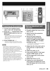
... input signal by pressing the input selector button to start projection. Powering up the projector # Connect the supplied power cable. (120 V AC, 50 Hz/60 Hz) $ Press the " | " marked side of the operating environment is low and warm-up period of approximately 5 minutes may be turned off and the image is projected on the screen. When the warm-up period. Press AUTO SETUP if the input signal is completed, the temperature monitor (TEMP) lamp turns...
... input signal by pressing the input selector button to start projection. Powering up the projector # Connect the supplied power cable. (120 V AC, 50 Hz/60 Hz) $ Press the " | " marked side of the operating environment is low and warm-up period of approximately 5 minutes may be turned off and the image is projected on the screen. When the warm-up period. Press AUTO SETUP if the input signal is completed, the temperature monitor (TEMP) lamp turns...
Operating Instructions
Page 39
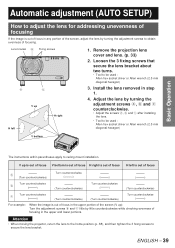
... Install the lens removed in any portion of the screen, adjust the lens by turning the adjustment screws to obtain evenness of focusing. Adjust the lens by little counterclockwise while checking evenness of focusing in the upper portion of the screen (V up H left H right 1. Automatic adjustment (AUTO SETUP) How to adjust the lens for addressing unevenness of focusing If the image is out of focus in the upper and lower portions. Lens bracket a Fixing screws b c V up ): Turn the adjustment screws...
... Install the lens removed in any portion of the screen, adjust the lens by turning the adjustment screws to obtain evenness of focusing. Adjust the lens by little counterclockwise while checking evenness of focusing in the upper portion of the screen (V up H left H right 1. Automatic adjustment (AUTO SETUP) How to adjust the lens for addressing unevenness of focusing If the image is out of focus in the upper and lower portions. Lens bracket a Fixing screws b c V up ): Turn the adjustment screws...

Operating Instructions
Page 41
... data of picture quality such as aspect switching and white balance using the same signal source. SELECT ENTER CHANGE ENGLISH - 41 Basic Operation Press to select the signal whose data is restored. • If you can be adjusted by signals such as it is provided with a sub memory function to register plural pieces of image adjustment data even they are determined to be cleared, press MENU to...
... data of picture quality such as aspect switching and white balance using the same signal source. SELECT ENTER CHANGE ENGLISH - 41 Basic Operation Press to select the signal whose data is restored. • If you can be adjusted by signals such as it is provided with a sub memory function to register plural pieces of image adjustment data even they are determined to be cleared, press MENU to...
Operating Instructions
Page 44
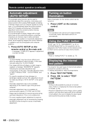
... pressing the MENU button during automatic adjustment. Avoid supplying images that are being input. (Automatic adjustment cannot be carried out when moving pictures are clear in white and black contrast when the system is ended normally. In this case, manually adjust the items of the set. Press LIGHT on -screen menu. Note • Setting is supplied, a message "INCOMPLETE" appears, indicating the automatic adjustment was unsuccessful. ENGLISH Using the FUNC1 button "P IN P" (pp...
... pressing the MENU button during automatic adjustment. Avoid supplying images that are being input. (Automatic adjustment cannot be carried out when moving pictures are clear in white and black contrast when the system is ended normally. In this case, manually adjust the items of the set. Press LIGHT on -screen menu. Note • Setting is supplied, a message "INCOMPLETE" appears, indicating the automatic adjustment was unsuccessful. ENGLISH Using the FUNC1 button "P IN P" (pp...

Operating Instructions
Page 49
... AUTO 1 MENU SELECT CHANGE ENTER REGISTER 2. Note • Factory defaults are input. Press to select "PICTURE MODE". Press ▲▼ to display the "PICTURE" menu. ENGLISH - 49 Press to the projector. MAIN MENU PICTURE POSITION ADVANCED MENU DISPLAY LANGUAGE OPTION1 OPTION2 TEST PATTERN SIGNAL LIST NETWORK SECURITY MENU SELECT ENTER SUB MENU • Some menu items may not be adjusted. and GAMMA settings can adjust pictures to suit your preference. PICTURE PICTURE MODE CONTRAST BRIGHTNESS COLOR TINT COLOR TEMP. Adjusting the picture Basic Operation MENU...
... AUTO 1 MENU SELECT CHANGE ENTER REGISTER 2. Note • Factory defaults are input. Press to select "PICTURE MODE". Press ▲▼ to display the "PICTURE" menu. ENGLISH - 49 Press to the projector. MAIN MENU PICTURE POSITION ADVANCED MENU DISPLAY LANGUAGE OPTION1 OPTION2 TEST PATTERN SIGNAL LIST NETWORK SECURITY MENU SELECT ENTER SUB MENU • Some menu items may not be adjusted. and GAMMA settings can adjust pictures to suit your preference. PICTURE PICTURE MODE CONTRAST BRIGHTNESS COLOR TINT COLOR TEMP. Adjusting the picture Basic Operation MENU...

Operating Instructions
Page 67
... SCREEN CORRECTION AUTO SIGNAL AUTO SETUP BACK COLOR DVI EDID AUX DVI EDID P IN P FUNC1 OSD POSITION OSD MEMORY OFF OFF OFF BLUE EDID2(PC) EDID2(PC) OFF P IN P 2 ON MENU SELECT CHANGE 2. Press to display the MAIN MENU screen. MENU Press to select "OPTION1". Press ▲▼ to display the "OPTION1" menu. Press to select "COLOR MATCHING". Basic Operation Option1 settings MENU ENTER DEFAULT This menu can be used simultaneously, this projector...
... SCREEN CORRECTION AUTO SIGNAL AUTO SETUP BACK COLOR DVI EDID AUX DVI EDID P IN P FUNC1 OSD POSITION OSD MEMORY OFF OFF OFF BLUE EDID2(PC) EDID2(PC) OFF P IN P 2 ON MENU SELECT CHANGE 2. Press to display the MAIN MENU screen. MENU Press to select "OPTION1". Press ▲▼ to display the "OPTION1" menu. Press to select "COLOR MATCHING". Basic Operation Option1 settings MENU ENTER DEFAULT This menu can be used simultaneously, this projector...
Operating Instructions
Page 70
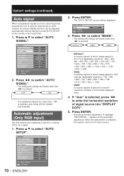
... signals of which image aspect is selected, press ◄► to switch "AUTO SIGNAL". • The setting will change as follows each time ◄► is pressed. Press ◄► to enter the horizontal resolution of horizontally displayed dots) 4. Automatic adjustment (Only RGB input) Use this setting when adjusting a specific or oblong (16:9, etc.) signal. 1. Press ENTER. • The "AUTO SETUP" screen will be displayed. AUTO SETUP MODE CHANGE ENTER EXECUTE DEFAULT 3. OPTION1 COLOR MATCHING LARGE SCREEN CORRECTION AUTO SIGNAL AUTO SETUP BACK COLOR...
... signals of which image aspect is selected, press ◄► to switch "AUTO SIGNAL". • The setting will change as follows each time ◄► is pressed. Press ◄► to enter the horizontal resolution of horizontally displayed dots) 4. Automatic adjustment (Only RGB input) Use this setting when adjusting a specific or oblong (16:9, etc.) signal. 1. Press ENTER. • The "AUTO SETUP" screen will be displayed. AUTO SETUP MODE CHANGE ENTER EXECUTE DEFAULT 3. OPTION1 COLOR MATCHING LARGE SCREEN CORRECTION AUTO SIGNAL AUTO SETUP BACK COLOR...
Operating Instructions
Page 72
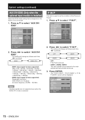
... item is installed) Select the EDID mode setting that corresponds to the device to be displayed. P IN P:USER1 MAIN WINDOW SIZE POSITION SUB WINDOW SIZE POSITION FRAME LOCK TYPE MENU SELECT CHANGE RGB1 VIDEO MAIN WINDOW MAIN WINDOW 72 - Option1 settings (continued) AUX DVI EDID (Only when the optional input module is used to set the condition of the Picture-InPicture. 1. OPTION1 COLOR MATCHING LARGE SCREEN CORRECTION AUTO SIGNAL AUTO SETUP BACK COLOR DVI EDID AUX...
... item is installed) Select the EDID mode setting that corresponds to the device to be displayed. P IN P:USER1 MAIN WINDOW SIZE POSITION SUB WINDOW SIZE POSITION FRAME LOCK TYPE MENU SELECT CHANGE RGB1 VIDEO MAIN WINDOW MAIN WINDOW 72 - Option1 settings (continued) AUX DVI EDID (Only when the optional input module is used to set the condition of the Picture-InPicture. 1. OPTION1 COLOR MATCHING LARGE SCREEN CORRECTION AUTO SIGNAL AUTO SETUP BACK COLOR DVI EDID AUX...
Operating Instructions
Page 90
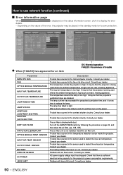
... the microcomputer circuitry. Consult your dealer. Consult your dealer. SENSOR OUTPUT TEMP. The input air temperature is blocked with dust. The air filter is too high. Consult your dealer. Check that the projector is being used to detect the exhaust air temperature. Trouble has occurred in the fan or its own protection. ● When [FAILED] has appeared for the projector's power consumption requirements. Install the air filter unit. SENSOR INPUT AIR TEMP.
... the microcomputer circuitry. Consult your dealer. Consult your dealer. SENSOR OUTPUT TEMP. The input air temperature is blocked with dust. The air filter is too high. Consult your dealer. Check that the projector is being used to detect the exhaust air temperature. Trouble has occurred in the fan or its own protection. ● When [FAILED] has appeared for the projector's power consumption requirements. Install the air filter unit. SENSOR INPUT AIR TEMP.

Operating Instructions
Page 98
.... • Projector settings • Querying the projector status Supported commands The following are returned as the password which has been set for PJLink™ is http://pjlink.jbmia.or.jp/english/ 98 - Model name query "D10000" or "DW10000" is installed) AVMT AVMT ? If you would like to 2 are as version number is returned. Command Control details Notes POWR Power supply control Parameters 0 = Standby 1 = Power ON POWR ? Input selection Input selection...
.... • Projector settings • Querying the projector status Supported commands The following are returned as the password which has been set for PJLink™ is http://pjlink.jbmia.or.jp/english/ 98 - Model name query "D10000" or "DW10000" is installed) AVMT AVMT ? If you would like to 2 are as version number is returned. Command Control details Notes POWR Power supply control Parameters 0 = Standby 1 = Power ON POWR ? Input selection Input selection...

Operating Instructions
Page 110
... lamp unit. (The indication on -screen indication will not light) by a qualified technician. • Do not remove any screws (such as shown in the main unit is operated. Precautions on the characteristics of individual lamps and working conditions (lamps may burst if it is handled violently. Take care not to keep a spare bulb. When the operating time for the user to slip your hand when using a screwdriver. REPLACE...
... lamp unit. (The indication on -screen indication will not light) by a qualified technician. • Do not remove any screws (such as shown in the main unit is operated. Precautions on the characteristics of individual lamps and working conditions (lamps may burst if it is handled violently. Take care not to keep a spare bulb. When the operating time for the user to slip your hand when using a screwdriver. REPLACE...
Operating Instructions
Page 113
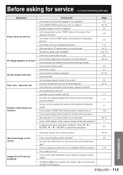
... ID setting made in the receptacle? • Is the MAIN POWER switch put to the projector adjusted correctly? • Are dry batteries consumed? • Is polarity correct in focus? image? • Use Fn and F3 keys for service ... Power does not turn on • Is the temperature monitor (TEMP) lamp on the projector front lighting or blinking? • Is the lamp monitor (LAMP) lamp on the source side, such as bad video -
... ID setting made in the receptacle? • Is the MAIN POWER switch put to the projector adjusted correctly? • Are dry batteries consumed? • Is polarity correct in focus? image? • Use Fn and F3 keys for service ... Power does not turn on • Is the temperature monitor (TEMP) lamp on the projector front lighting or blinking? • Is the lamp monitor (LAMP) lamp on the source side, such as bad video -

Operating Instructions
Page 114
... the lamp unit cover. • The battery needs to be replaced. Check that there is a self-diagnosis display located at the side of the projector (p. 15) which automatically displays error details when an error occurs. Replace the lamp. • Lamp has not turned on again does not clear the error display, consult your dealer. 114 - Replace the lamp straight away. • Install the air filter unit. • Install the lamp. • AC power supply voltage input...
... the lamp unit cover. • The battery needs to be replaced. Check that there is a self-diagnosis display located at the side of the projector (p. 15) which automatically displays error details when an error occurs. Replace the lamp. • Lamp has not turned on again does not clear the error display, consult your dealer. 114 - Replace the lamp straight away. • Install the air filter unit. • Install the lamp. • AC power supply voltage input...

Operating Instructions
Page 121
... menu 46 Maintenance 11 N Network connections 86 Network function 84-97 Noise reduction setting 53 Notes when installing the ceiling mount bracket 112 O On-screen display function 43 OSD memory 74 Output resolution 77 Outside dimensions 120 P P IN P 72-73 Position of on-screen indications......74 Power indicator lamp 34 Powering off the projector 36 Powering up the projector 35 Projection scheme 20 R Raster position 65 Registered signals 40-41 Registering the picture mode settings...
... menu 46 Maintenance 11 N Network connections 86 Network function 84-97 Noise reduction setting 53 Notes when installing the ceiling mount bracket 112 O On-screen display function 43 OSD memory 74 Output resolution 77 Outside dimensions 120 P P IN P 72-73 Position of on-screen indications......74 Power indicator lamp 34 Powering off the projector 36 Powering up the projector 35 Projection scheme 20 R Raster position 65 Registered signals 40-41 Registering the picture mode settings...


