Owner Manual
Page 1
Contents AV Receiver TX-SR700/700E TX-SR600/600E Instruction Manual Before using 2 Facilities and connections 8 Setup and operation 36 Thank you to obtain optimum performance and listening enjoyment from your new AV Receiver. Following the instructions in the unit. Please retain this manual will enable you for future reference. Remote controller 63 Appendix 76 Please read this manual thoroughly before making connections and plugging in this manual for purchasing the Onkyo AV Receiver.
Contents AV Receiver TX-SR700/700E TX-SR600/600E Instruction Manual Before using 2 Facilities and connections 8 Setup and operation 36 Thank you to obtain optimum performance and listening enjoyment from your new AV Receiver. Following the instructions in the unit. Please retain this manual will enable you for future reference. Remote controller 63 Appendix 76 Please read this manual thoroughly before making connections and plugging in this manual for purchasing the Onkyo AV Receiver.
Owner Manual
Page 4
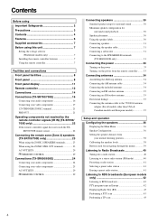
... 23 When using the ZONE 2 PRE OUT terminals 23 AC OUTLETS 29 REMOTE CONTROL 29 Connections (TX-SR600/600E 24 Connecting your audio components 24 Connecting your video components 25 AC OUTLETS 29 REMOTE CONTROL 29 Connecting speakers 30 Standard speaker setup for surround sound 30 Minimum ...the speaker cable 31 Connecting a subwoofer 31 Connecting to the SPEAKERS B terminals (TX-SR600/600E only 31 Connecting the power 33 Turning on the power 33 Turning on the power from the remote controller ........ 33 Connecting antennas 34 Assembling the AM loop antenna 34 Connecting the...
... 23 When using the ZONE 2 PRE OUT terminals 23 AC OUTLETS 29 REMOTE CONTROL 29 Connections (TX-SR600/600E 24 Connecting your audio components 24 Connecting your video components 25 AC OUTLETS 29 REMOTE CONTROL 29 Connecting speakers 30 Standard speaker setup for surround sound 30 Minimum ...the speaker cable 31 Connecting a subwoofer 31 Connecting to the SPEAKERS B terminals (TX-SR600/600E only 31 Connecting the power 33 Turning on the power 33 Turning on the power from the remote controller ........ 33 Connecting antennas 34 Assembling the AM loop antenna 34 Connecting the...
Owner Manual
Page 5
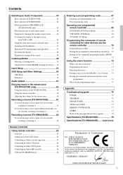
... 46 Using the sleep time (remote controller only 47 Listening with the corresponding technical standards such as EN60065, EN55013, EN55020 and EN61000-3-2, -3-3. GERMERING, GERMANY I. MORI ONKYO EUROPE ELECTRONICS GmbH 5 Contents Selecting an Audio Component 44 Basic operation (TX-SR700/700E 44 Basic operation (TX-SR600/600E 45 Selecting speakers (SPEAKERS A, B) (TX-SR600/600E only 45 Selecting the...
... 46 Using the sleep time (remote controller only 47 Listening with the corresponding technical standards such as EN60065, EN55013, EN55020 and EN61000-3-2, -3-3. GERMERING, GERMANY I. MORI ONKYO EUROPE ELECTRONICS GmbH 5 Contents Selecting an Audio Component 44 Basic operation (TX-SR700/700E 44 Basic operation (TX-SR600/600E 45 Selecting speakers (SPEAKERS A, B) (TX-SR600/600E only 45 Selecting the...
Owner Manual
Page 6
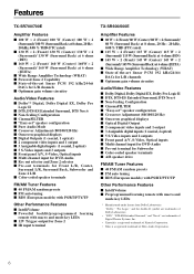
... tuning I RDS (European models) with PS/RT/PTY/TP Other Performance Features I IntelliVolume I Preprogrammed learning remote with macro and mode-key LEDs * Manufactured under license from Dolby Laboratories. Features TX-SR700/700E Amplifier Features I 100 W × 2 (Front)/ 100 W (Center)/ 100 W ×... (European models) with PS/RT/PTY/TP Other Performance Features I IntelliVolume I Powerful backlit/preprogrammed learning remote with macro and mode-key LEDs I 12V Trigger output for Zone 2 I IR input terminal TX-SR600/600E Amplifier Features I 80 W × 2 (Front)/ 80 W (Center)/ 80 W ×...
... tuning I RDS (European models) with PS/RT/PTY/TP Other Performance Features I IntelliVolume I Preprogrammed learning remote with macro and mode-key LEDs * Manufactured under license from Dolby Laboratories. Features TX-SR700/700E Amplifier Features I 100 W × 2 (Front)/ 100 W (Center)/ 100 W ×... (European models) with PS/RT/PTY/TP Other Performance Features I IntelliVolume I Powerful backlit/preprogrammed learning remote with macro and mode-key LEDs I 12V Trigger output for Zone 2 I IR input terminal TX-SR600/600E Amplifier Features I 80 W × 2 (Front)/ 80 W (Center)/ 80 W ×...
Owner Manual
Page 7
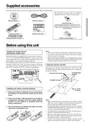
... or different kinds of batteries. • To avoid corrosion, remove the batteries if the remote controller will not operate. 7 AM loop antenna × 1 RC-482M Remote controller × 1 TX-SR700/700E: RC-482M TX-SR600/600E: RC-480M Batteries (AA, R6 or UM-3) × 2 Front Left Front Left...unit. Its buttons may be available depending on the area which it was purchased. Remote control sensor TX-SR700/700E/ 600/600E STANDBY indicator Installing the remote controller batteries 1. Placing the TX-SR700/700E/600/600E behind such doors may cause operational interference. • Do...
... or different kinds of batteries. • To avoid corrosion, remove the batteries if the remote controller will not operate. 7 AM loop antenna × 1 RC-482M Remote controller × 1 TX-SR700/700E: RC-482M TX-SR600/600E: RC-480M Batteries (AA, R6 or UM-3) × 2 Front Left Front Left...unit. Its buttons may be available depending on the area which it was purchased. Remote control sensor TX-SR700/700E/ 600/600E STANDBY indicator Installing the remote controller batteries 1. Placing the TX-SR700/700E/600/600E behind such doors may cause operational interference. • Do...
Owner Manual
Page 9
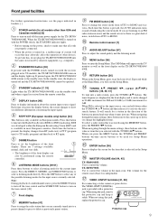
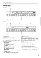
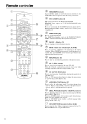
...is turned on, a sudden surge of the button you different information concerning the input signal. MASTER VOLUME dial [44, 45] TX-SR600/600E: Use to go back one . TX-SR700/700E: Use to the standby state. POWER switch (for all cords are listening to an FM radio station in most ... a listening mode for the current input source. LISTENING MODE buttons [49-51] Press these buttons to set the brightness of noise, switch from the remote controller. Each time this button is provided with the TUNING / buttons. The VIDEO 4 INPUT (DIGITAL) jack is pressed, the AUTO indication turns on...
...is turned on, a sudden surge of the button you different information concerning the input signal. MASTER VOLUME dial [44, 45] TX-SR600/600E: Use to go back one . TX-SR700/700E: Use to the standby state. POWER switch (for all cords are listening to an FM radio station in most ... a listening mode for the current input source. LISTENING MODE buttons [49-51] Press these buttons to set the brightness of noise, switch from the remote controller. Each time this button is provided with the TUNING / buttons. The VIDEO 4 INPUT (DIGITAL) jack is pressed, the AUTO indication turns on...
Owner Manual
Page 10
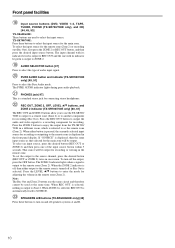
... the desired button (REC OUT or ZONE 2) twice in the front panel display. SPEAKERS A/B buttons (TX-SR600/600E only) [45] Press these buttons to ZONE 2. AUDIO SELECTOR button [47] Press to the remote zone is turned off , then either button is selected. To select an input source, press the desired...VIDEO 1-4, TAPE, TUNER, PHONO (TX-SR700/700E only), and CD) [44, 45, 53] TX-SR600/600E: These buttons are used at the same time. Press the ZONE 2 button to enjoy the output from the TX-SR700/ 700E in a different room, which is a standard stereo jack for the remote zone (Zone 2) or recording out...
... the desired button (REC OUT or ZONE 2) twice in the front panel display. SPEAKERS A/B buttons (TX-SR600/600E only) [45] Press these buttons to ZONE 2. AUDIO SELECTOR button [47] Press to the remote zone is turned off , then either button is selected. To select an input source, press the desired...VIDEO 1-4, TAPE, TUNER, PHONO (TX-SR700/700E only), and CD) [44, 45, 53] TX-SR600/600E: These buttons are used at the same time. Press the ZONE 2 button to enjoy the output from the TX-SR700/ 700E in a different room, which is a standard stereo jack for the remote zone (Zone 2) or recording out...
Owner Manual
Page 11
...of these indicators lights to another (Rec Out). Turns off when placed into the monaural mode. ZONE 2 indicator (TX-SR700/700E only) Lights when using the remote zone (Zone 2). Tuning indicators TUNED indicator Lights when a radio station is selected. However, does not show the format... When the DISPLAY button is currently in the stereo mode. REC OUT indicator (TX-SR700/700E only) Lights when recording the input source from one of the current input source. SPEAKERS A/B indicators (TX-SR600/600E only) Indicates which speaker system is pressed, shows the listening mode and ...
...of these indicators lights to another (Rec Out). Turns off when placed into the monaural mode. ZONE 2 indicator (TX-SR700/700E only) Lights when using the remote zone (Zone 2). Tuning indicators TUNED indicator Lights when a radio station is selected. However, does not show the format... When the DISPLAY button is currently in the stereo mode. REC OUT indicator (TX-SR700/700E only) Lights when recording the input source from one of the current input source. SPEAKERS A/B indicators (TX-SR600/600E only) Indicates which speaker system is pressed, shows the listening mode and ...
Owner Manual
Page 12
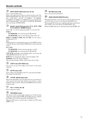
... buttons and indicators [44, 45, 64-66] Press to select the component to be operated by the remote controller. When a MODE button is pressed, it will also light whenever any other Onkyo components connected to turn off . Be aware that pressing the STANDBY button only places the TXSR700/700E/600/... when playing a DVD-Video. [65] CD/TAPE/DVD/MD operation buttons [63-66] Press to turn on the TX-SR700/700E/600/600E. SLEEP button [47] Press to set the TX-SR700/700E/600/ 600E to operate other operation button is selected, also press to select a preset channel for 8 seconds...
... buttons and indicators [44, 45, 64-66] Press to select the component to be operated by the remote controller. When a MODE button is pressed, it will also light whenever any other Onkyo components connected to turn off . Be aware that pressing the STANDBY button only places the TXSR700/700E/600/... when playing a DVD-Video. [65] CD/TAPE/DVD/MD operation buttons [63-66] Press to turn on the TX-SR700/700E/600/600E. SLEEP button [47] Press to set the TX-SR700/700E/600/ 600E to operate other operation button is selected, also press to select a preset channel for 8 seconds...
Owner Manual
Page 13
... press the DIRECT button to turn off the tone control and the SURR button to turn the CinemaFILTER function on the remote zone (ZONE 2) (not used with the TX-SR600/600E). CINE FLTR: Depending on the listening mode, you want to start playback (SEARCH). [65] When in the ... a listening mode. [51] Note: During playback of the remote controller. Numeric key/Listening mode, SP A, SP B, CINE FLTR, DISPLAY, DIMMER buttons 1 to display the Setup Menu on and off . [52] DISPLAY: For changing the display in conjunction with the TX-SR600/600E. SETUP button [36] Press to 9, +10, --/---,...
... press the DIRECT button to turn off the tone control and the SURR button to turn the CinemaFILTER function on the remote zone (ZONE 2) (not used with the TX-SR600/600E). CINE FLTR: Depending on the listening mode, you want to start playback (SEARCH). [65] When in the ... a listening mode. [51] Note: During playback of the remote controller. Numeric key/Listening mode, SP A, SP B, CINE FLTR, DISPLAY, DIMMER buttons 1 to display the Setup Menu on and off . [52] DISPLAY: For changing the display in conjunction with the TX-SR600/600E. SETUP button [36] Press to 9, +10, --/---,...
Owner Manual
Page 15
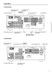
TX-SR700E SURROUND BACK AC OUTLETS AC 230-240V 50 Hz SWITCHED TOTAL 100W MAX. Connecting a subwoofer [31] Connecting your audio components [16] 12V TRIGGER ZONE 2 terminal [21] Connecting antennas [34] REMOTE CONTROL [27] Connecting speakers [31] AC OUTLETS [26] ANTENNA FM AM 75 GND R... OUT When using the ZONE 2 PRE OUT [21] terminals [23] When using the ZONE 2 SPEAKERS terminals [23] TX-SR600/600E Connecting your audio components [24] REMOTE Connecting antennas [34] CONTROL [27] Connecting speakers [31] AC OUTLETS [26] ANTENNA FM AM 75 DIGITAL INPUT OPTICAL ...
TX-SR700E SURROUND BACK AC OUTLETS AC 230-240V 50 Hz SWITCHED TOTAL 100W MAX. Connecting a subwoofer [31] Connecting your audio components [16] 12V TRIGGER ZONE 2 terminal [21] Connecting antennas [34] REMOTE CONTROL [27] Connecting speakers [31] AC OUTLETS [26] ANTENNA FM AM 75 GND R... OUT When using the ZONE 2 PRE OUT [21] terminals [23] When using the ZONE 2 SPEAKERS terminals [23] TX-SR600/600E Connecting your audio components [24] REMOTE Connecting antennas [34] CONTROL [27] Connecting speakers [31] AC OUTLETS [26] ANTENNA FM AM 75 DIGITAL INPUT OPTICAL ...
Owner Manual
Page 17
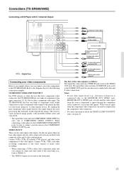
...output (surround L/R) R (red) L (white) Analog audio output (front L/R) R (red) Digital audio output (coaxial) Connecting your video components to the TX-SR700/700E. VIDEO IN/OUT These are located on the front panel. Connect VCRs, VTRs, LD players, DVD players, and other display device. COMPONENT VIDEO... VIDEO INPUT 2 INPUT 1 OUTPUT Y PB DIGITAL INPUT OPTICAL 2 1 DIGITAL VIDEO 3 OUTPUT COAXIAL IN OPTICAL VIDEO 2 OUT IN VIDEO 1 OUT IN REMOTE CONTROL PR DVD IN MONITOR OUT V ZONE 2 12 V TRIGGE OUT SUBWOOFER PRE OUT IN L R CD COAXIAL DIGITAL INPUT OUT IN IN OUT IN...
...output (surround L/R) R (red) L (white) Analog audio output (front L/R) R (red) Digital audio output (coaxial) Connecting your video components to the TX-SR700/700E. VIDEO IN/OUT These are located on the front panel. Connect VCRs, VTRs, LD players, DVD players, and other display device. COMPONENT VIDEO... VIDEO INPUT 2 INPUT 1 OUTPUT Y PB DIGITAL INPUT OPTICAL 2 1 DIGITAL VIDEO 3 OUTPUT COAXIAL IN OPTICAL VIDEO 2 OUT IN VIDEO 1 OUT IN REMOTE CONTROL PR DVD IN MONITOR OUT V ZONE 2 12 V TRIGGE OUT SUBWOOFER PRE OUT IN L R CD COAXIAL DIGITAL INPUT OUT IN IN OUT IN...

Owner Manual
Page 18
...TX-SR700/700E. Make sure that you want to the DVD S VIDEO IN jack with 2-Channel (L/R) Audio Output ANTENNA FM AM 75 R L PHONO IN GND COMPONENT VIDEO INPUT 2 INPUT 1 OUTPUT Y DIGITAL INPUT OPTICAL 2 1 DIGITAL VIDEO 3 OUTPUT COAXIAL IN OPTICAL VIDEO 2 OUT IN VIDEO 1 OUT IN PB REMOTE...SUBWOOFER (5.1-channel input) jacks of the DVD player. If the digital connection is set for digital input at the COAXIAL jack (COAX). Connections (TX-SR700/700E) Connecting a DVD Player with an S video cable. With the initial settings of connector on the DVD player. 18 Y PB ...
...TX-SR700/700E. Make sure that you want to the DVD S VIDEO IN jack with 2-Channel (L/R) Audio Output ANTENNA FM AM 75 R L PHONO IN GND COMPONENT VIDEO INPUT 2 INPUT 1 OUTPUT Y DIGITAL INPUT OPTICAL 2 1 DIGITAL VIDEO 3 OUTPUT COAXIAL IN OPTICAL VIDEO 2 OUT IN VIDEO 1 OUT IN PB REMOTE...SUBWOOFER (5.1-channel input) jacks of the DVD player. If the digital connection is set for digital input at the COAXIAL jack (COAX). Connections (TX-SR700/700E) Connecting a DVD Player with an S video cable. With the initial settings of connector on the DVD player. 18 Y PB ...
Owner Manual
Page 19
...to the COMPONENT VIDEO INPUT 1 jacks, this must be changed at "Input Setup" → "Component Video" (see page 53). 6. Connections (TX-SR700/700E) : Signal flow 6. Make sure that you properly connect the left channels to the L jacks and the right channels to the R ...Video output L (white) Analog audio output R (red) ANTENNA FM AM 75 R L PHONO IN GND COMPONENT VIDEO INPUT 2 INPUT 1 OUTPUT Y PB REMOT PR CONTRO DIGITAL INPUT OPTICAL 2 1 DIGITAL VIDEO 3 OUTPUT COAXIAL IN OPTICAL VIDEO 2 OUT IN VIDEO 1 OUT IN DVD MONITOR IN OUT ZONE V SUBWOOFER...
...to the COMPONENT VIDEO INPUT 1 jacks, this must be changed at "Input Setup" → "Component Video" (see page 53). 6. Connections (TX-SR700/700E) : Signal flow 6. Make sure that you properly connect the left channels to the L jacks and the right channels to the R ...Video output L (white) Analog audio output R (red) ANTENNA FM AM 75 R L PHONO IN GND COMPONENT VIDEO INPUT 2 INPUT 1 OUTPUT Y PB REMOT PR CONTRO DIGITAL INPUT OPTICAL 2 1 DIGITAL VIDEO 3 OUTPUT COAXIAL IN OPTICAL VIDEO 2 OUT IN VIDEO 1 OUT IN DVD MONITOR IN OUT ZONE V SUBWOOFER...
Owner Manual
Page 20
... and connect the video input jack of the TX-SR700/ 700E is set for VIDEO 2 (----). Connecting a DVD recorder or other digital video recording device (VIDEO 2) ANTENNA FM AM 75 R L PHONO IN GND COMPONENT VIDEO INPUT 2 INPUT 1 OUTPUT Y PB REMOT CONTRO PR DIGITAL INPUT OPTICAL 2 1 DIGITAL VIDEO... L (white) Analog audio input R (red) L (white) Analog audio output R (red) : Signal flow 7. With the initial settings of the TX-SR700/ 700E. If you properly connect the left channels to the L jacks and the right channels to the VIDEO 2 OUT audio jacks of connector on...
... and connect the video input jack of the TX-SR700/ 700E is set for VIDEO 2 (----). Connecting a DVD recorder or other digital video recording device (VIDEO 2) ANTENNA FM AM 75 R L PHONO IN GND COMPONENT VIDEO INPUT 2 INPUT 1 OUTPUT Y PB REMOT CONTRO PR DIGITAL INPUT OPTICAL 2 1 DIGITAL VIDEO... L (white) Analog audio input R (red) L (white) Analog audio output R (red) : Signal flow 7. With the initial settings of the TX-SR700/ 700E. If you properly connect the left channels to the L jacks and the right channels to the VIDEO 2 OUT audio jacks of connector on...
Owner Manual
Page 21
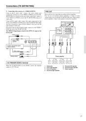
...COMPONENT VIDEO INPUT 2 INPUT 1 OUTPUT Y L PB DIGITAL INPUT OPTICAL 2 1 DIGITAL VIDEO 3 OUTPUT COAXIAL IN OPTICAL VIDEO 2 OUT IN VIDEO 1 OUT IN REMOTE PR CONTROL DVD IN MONITOR OUT V R ZONE 2 12 V TRIGGER OUT SUBWOOFER PRE OUT IN L R CD COAXIAL DIGITAL INPUT OUT IN IN OUT IN TAPE... back speaker 7. S Video output PRE OUT These jacks are for connecting an auxiliary power amplifier. Center speaker 21 You can with the TX-SR700/700E alone. Video camera/Video game (VIDEO 4 INPUT) Video output Left (white) Analog output Right (red) Subwoofer Front Surround ...
...COMPONENT VIDEO INPUT 2 INPUT 1 OUTPUT Y L PB DIGITAL INPUT OPTICAL 2 1 DIGITAL VIDEO 3 OUTPUT COAXIAL IN OPTICAL VIDEO 2 OUT IN VIDEO 1 OUT IN REMOTE PR CONTROL DVD IN MONITOR OUT V R ZONE 2 12 V TRIGGER OUT SUBWOOFER PRE OUT IN L R CD COAXIAL DIGITAL INPUT OUT IN IN OUT IN TAPE... back speaker 7. S Video output PRE OUT These jacks are for connecting an auxiliary power amplifier. Center speaker 21 You can with the TX-SR700/700E alone. Video camera/Video game (VIDEO 4 INPUT) Video output Left (white) Analog output Right (red) Subwoofer Front Surround ...
Owner Manual
Page 22
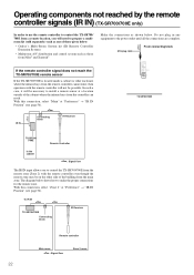
...IR Receiver TX-SR700 /700E In the cabinet Remote Controller : Signal flow The IR IN input allows you will be necessary to the power outlet until all the connections are complete. With this connection, select "Main" at a location outside of those given below: • Onkyo's Multi-...Room System kit (IR Remote Controller Extension System) • Multiroom A/V distribution and control system such as shown below shows how to make the proper ...
...IR Receiver TX-SR700 /700E In the cabinet Remote Controller : Signal flow The IR IN input allows you will be necessary to the power outlet until all the connections are complete. With this connection, select "Main" at a location outside of those given below: • Onkyo's Multi-...Room System kit (IR Remote Controller Extension System) • Multiroom A/V distribution and control system such as shown below shows how to make the proper ...
Owner Manual
Page 23
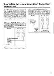
... for example, place speakers in the main room, you can enjoy two different kinds of the speaker impedance (see page 31). 23 Main Room Remote Zone (Zone 2) TX-SR700/700E FRONT SURROUND CENTER ZONE 2 L L PRE OUT R R SURROUND BACK Zone 2 Left speaker Zone 2 Right speaker Left (white) ...Right (red) Power amplifier ZONE 2 SPEAKERS L R TX-SR700/700E Note: It is important to control the TX-SR700/700E from the remote zone (Zone 2) with the remote controller even though the remote zone is referred to as the main room while the separate room is physically ...
... for example, place speakers in the main room, you can enjoy two different kinds of the speaker impedance (see page 31). 23 Main Room Remote Zone (Zone 2) TX-SR700/700E FRONT SURROUND CENTER ZONE 2 L L PRE OUT R R SURROUND BACK Zone 2 Left speaker Zone 2 Right speaker Left (white) ...Right (red) Power amplifier ZONE 2 SPEAKERS L R TX-SR700/700E Note: It is important to control the TX-SR700/700E from the remote zone (Zone 2) with the remote controller even though the remote zone is referred to as the main room while the separate room is physically ...
Owner Manual
Page 25
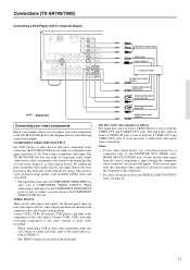
... connectors for direct component video output to the matrix decoder of a television, projector, or other devices that have component video connectors, the TX-SR600/600E has two banks of component video input connectors (Y, PB, PR) for the following connection examples. Connect VCRs, VTRs, LD players... OPTICAL 2 1 DIGITAL DIGITAL OUTPUT INPUT OPTICAL COAXIAL COMPONENT VIDEO INPUT 2 INPUT 1 OUTPUT Y VIDEO 3 VIDEO 2 VIDEO 1 IN IN OUT IN PB REMOTE CONTROL PR DVD MONITOR IN OUT VIDEO CD IN L SUBWOOFER PRE OUT R TAPE OUT IN S VIDEO IN IN OUT IN FRONT SURR CENTER L L ...
... connectors for direct component video output to the matrix decoder of a television, projector, or other devices that have component video connectors, the TX-SR600/600E has two banks of component video input connectors (Y, PB, PR) for the following connection examples. Connect VCRs, VTRs, LD players... OPTICAL 2 1 DIGITAL DIGITAL OUTPUT INPUT OPTICAL COAXIAL COMPONENT VIDEO INPUT 2 INPUT 1 OUTPUT Y VIDEO 3 VIDEO 2 VIDEO 1 IN IN OUT IN PB REMOTE CONTROL PR DVD MONITOR IN OUT VIDEO CD IN L SUBWOOFER PRE OUT R TAPE OUT IN S VIDEO IN IN OUT IN FRONT SURR CENTER L L ...
Owner Manual
Page 26
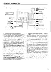
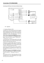
... jacks. DVD player (DVD) L (white) R (red) Analog audio output Digital audio output (coaxial) With the initial settings of connector on the TX-SR600/600E. If the digital connection is set for digital input at "Input Setup" → "Digital Input" (see page 54). Or if the device has... INPUT OPTICAL 2 1 DIGITAL DIGITAL OUTPUT INPUT OPTICAL COAXIAL COMPONENT VIDEO INPUT 2 INPUT 1 OUTPUT Y VIDEO 3 VIDEO 2 VIDEO 1 IN IN OUT IN PB REMOTE CONTROL PR DVD MONITOR IN OUT VIDEO CD IN L SUBWOOFER PRE OUT R TAPE OUT IN S VIDEO IN IN OUT IN FRONT SURR CENTER L L R ...
... jacks. DVD player (DVD) L (white) R (red) Analog audio output Digital audio output (coaxial) With the initial settings of connector on the TX-SR600/600E. If the digital connection is set for digital input at "Input Setup" → "Digital Input" (see page 54). Or if the device has... INPUT OPTICAL 2 1 DIGITAL DIGITAL OUTPUT INPUT OPTICAL COAXIAL COMPONENT VIDEO INPUT 2 INPUT 1 OUTPUT Y VIDEO 3 VIDEO 2 VIDEO 1 IN IN OUT IN PB REMOTE CONTROL PR DVD MONITOR IN OUT VIDEO CD IN L SUBWOOFER PRE OUT R TAPE OUT IN S VIDEO IN IN OUT IN FRONT SURR CENTER L L R ...


