
Owner Manual
Page 1
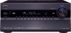
Please read this manual thoroughly before making connections and plugging in this manual for purchasing an Onkyo AV Receiver. Following the instructions in the unit. Contents Introduction 2 Connection 18 Turning On & First Time Setup .....43 Basic Operations 62 Using the Listening Modes ........76 Advanced... Setup 87 NET 115 Multi Zone 123 Controlling Other Components....132 Others 147 En Please retain this manual will enable you for future reference. AV Receiver TX-NR1007 Instruction Manual Thank you to obtain optimum performance and listening enjoyment from your new AV...
Please read this manual thoroughly before making connections and plugging in this manual for purchasing an Onkyo AV Receiver. Following the instructions in the unit. Contents Introduction 2 Connection 18 Turning On & First Time Setup .....43 Basic Operations 62 Using the Listening Modes ........76 Advanced... Setup 87 NET 115 Multi Zone 123 Controlling Other Components....132 Others 147 En Please retain this manual will enable you for future reference. AV Receiver TX-NR1007 Instruction Manual Thank you to obtain optimum performance and listening enjoyment from your new AV...
Owner Manual
Page 3
... installation. Preventing Hearing Loss Caution Excessive sound pressure from the AC power source. This is no guarantee that the plug is used in your Onkyo dealer. 3. models FCC Information for an extended period, remove the power cord from the AC outlet. 5. For models having a power cord...and on, the user is illegal without the permission of the following measures: • Reorient or relocate the receiving antenna. • Increase the separation between the equipment and receiver. • Connect the equipment into an outlet on the case. • This unit's top and rear panels...
... installation. Preventing Hearing Loss Caution Excessive sound pressure from the AC power source. This is no guarantee that the plug is used in your Onkyo dealer. 3. models FCC Information for an extended period, remove the power cord from the AC outlet. 5. For models having a power cord...and on, the user is illegal without the permission of the following measures: • Reorient or relocate the receiving antenna. • Increase the separation between the equipment and receiver. • Connect the equipment into an outlet on the case. • This unit's top and rear panels...

Owner Manual
Page 4
...the terminal which is marked with the letter N or coloured black. GROEBENZELL, GERMANY K. For European Models Declaration of Conformity We, ONKYO EUROPE ELECTRONICS GmbH LIEGNITZERSTRASSE 6, 82194 GROEBENZELL, GERMANY declare in own responsibility, that indicated on the plug. Specifications and operations are coloured...not match with the corresponding technical standards such as follows: The wire which is in compliance with the plug on the AV receiver's power cord (adapter varies from country to the terminal which is coloured brown must be connected to country.) Speaker cable ...
...the terminal which is marked with the letter N or coloured black. GROEBENZELL, GERMANY K. For European Models Declaration of Conformity We, ONKYO EUROPE ELECTRONICS GmbH LIEGNITZERSTRASSE 6, 82194 GROEBENZELL, GERMANY declare in own responsibility, that indicated on the plug. Specifications and operations are coloured...not match with the corresponding technical standards such as follows: The wire which is in compliance with the plug on the AV receiver's power cord (adapter varies from country to the terminal which is coloured brown must be connected to country.) Speaker cable ...
Owner Manual
Page 5
... 40 Connecting an RI Dock 41 Connecting a Universal Port Option Series 41 Connecting Onkyo V Components 42 Connecting the Power Cord 42 Turning On & First Time Setup Turning On the AV receiver 43 Turning On and Standby 43 First Time Setup 44 Monitor Setup 44 Selecting ...Remote Controller 135 Controlling a TV 136 Controlling a DVD Player or DVD Recorder 137 Controlling a VCR or PVR 138 Controlling a Satellite Receiver or Cable Receiver ...... 139 Controlling a CD Player, CD Recorder or MD Recorder 140 Controlling an RI Dock 141 Controlling a Cassette Recorder 142 Activities Setup...
... 40 Connecting an RI Dock 41 Connecting a Universal Port Option Series 41 Connecting Onkyo V Components 42 Connecting the Power Cord 42 Turning On & First Time Setup Turning On the AV receiver 43 Turning On and Standby 43 First Time Setup 44 Monitor Setup 44 Selecting ...Remote Controller 135 Controlling a TV 136 Controlling a DVD Player or DVD Recorder 137 Controlling a VCR or PVR 138 Controlling a Satellite Receiver or Cable Receiver ...... 139 Controlling a CD Player, CD Recorder or MD Recorder 140 Controlling an RI Dock 141 Controlling a Cassette Recorder 142 Activities Setup...
Owner Manual
Page 7
...movie soundtracks for many years to receive the SIRIUS or XM satellite radio service. All other intellectual property rights. All rights reserved. Taxes and a one-time activation fee may be THX Ultra2 Plus certified, it must install an Onkyo UP-HT1 HD Radio tuner module ... hack, manipulate or otherwise make available any home theater component can a product feature the THX Ultra2 Plus logo, which may apply. To receive HD Radio broadcasts, you superb performance for home theater playback. * "Xantech" is a registered trademark of quality and performance tests. Features-...
...movie soundtracks for many years to receive the SIRIUS or XM satellite radio service. All other intellectual property rights. All rights reserved. Taxes and a one-time activation fee may be THX Ultra2 Plus certified, it must install an Onkyo UP-HT1 HD Radio tuner module ... hack, manipulate or otherwise make available any home theater component can a product feature the THX Ultra2 Plus logo, which may apply. To receive HD Radio broadcasts, you superb performance for home theater playback. * "Xantech" is a registered trademark of quality and performance tests. Features-...
Owner Manual
Page 8
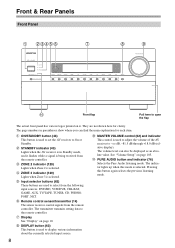
...information about the currently selected input source. J MASTER VOLUME control (62) and indicator This control is used to adjust the volume of the AV receiver to On or Standby. The indicator lights up when this button again selects the previous listening mode. 8 F Input selector buttons (62) These ..., and it . See "Volume Setup" on page 10. Pressing this mode is selected. B ON/STANDBY button (43) This button is used to set the AV receiver to -2 dB, -81.5 dB through +18.0 dB (relative display). Front & Rear Panels Front Panel B CDEFG H I DISPLAY button (63) This button is...
...information about the currently selected input source. J MASTER VOLUME control (62) and indicator This control is used to adjust the volume of the AV receiver to On or Standby. The indicator lights up when this button again selects the previous listening mode. 8 F Input selector buttons (62) These ..., and it . See "Volume Setup" on page 10. Pressing this mode is selected. B ON/STANDBY button (43) This button is used to set the AV receiver to -2 dB, -81.5 dB through +18.0 dB (relative display). Front & Rear Panels Front Panel B CDEFG H I DISPLAY button (63) This button is...
Owner Manual
Page 10
Y AUX INPUT (37) This input can be set to ON to set the AV receiver to On or Standby. LW: Front wide left LH: Front high left RH: Front high right RW: Front wide right FL: Front left C: Center FR: ... when the "Equalizer Settings" is set to "Audyssey" or Audyssey Dynamic Surround Expansion™ listening mode is being used . When set to OFF, the AV receiver is being used . It must be used by the current listening mode. The following abbreviations indicate which audio channels are jacks for composite video, analog...
Y AUX INPUT (37) This input can be set to ON to set the AV receiver to On or Standby. LW: Front wide left LH: Front high left RH: Front high right RW: Front wide right FL: Front left C: Center FR: ... when the "Equalizer Settings" is set to "Audyssey" or Audyssey Dynamic Surround Expansion™ listening mode is being used . When set to OFF, the AV receiver is being used . It must be used by the current listening mode. The following abbreviations indicate which audio channels are jacks for composite video, analog...

Owner Manual
Page 11
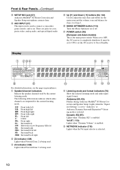
.... K Message area Displays various information. A commercially available IR emitter can be connected to the IR IN jack, allowing you to control the AV receiver while you can be connected to the IR OUT jack to pass IR (infrared) remote control signals through to suit your setup. Goes off when...) (70): Lights when tuned to a stereo FM station. TUNED (68): Lights when tuned to "Bi-Amp". N MUTING indicator (64) Flashes while the AV receiver is for AM or FM radio. AUTO (68): Lights when Auto Tuning mode is selected for connecting the component with optical digital audio outputs, such...
.... K Message area Displays various information. A commercially available IR emitter can be connected to the IR IN jack, allowing you to control the AV receiver while you can be connected to the IR OUT jack to pass IR (infrared) remote control signals through to suit your setup. Goes off when...) (70): Lights when tuned to a stereo FM station. TUNED (68): Lights when tuned to "Bi-Amp". N MUTING indicator (64) Flashes while the AV receiver is for AM or FM radio. AUTO (68): Lights when Auto Tuning mode is selected for connecting the component with optical digital audio outputs, such...

Owner Manual
Page 12
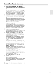
... The HDMI outputs are for connecting a TV or projector with a component video input. They're assignable, which means you can connect a cable/satellite receiver, settop box, etc. See "Component Video Input Setup" on page 51. L COMPONENT VIDEO MONITOR OUT These RCA component video outputs are for connecting a...in Zone 3. They're assignable, which means you can assign each one to an input selector to the 12-volt trigger input on another Onkyo AV component. They're assignable, which means you can assign each one to an input selector to a suitable wall outlet. AM ANTENNA These...
... The HDMI outputs are for connecting a TV or projector with a component video input. They're assignable, which means you can connect a cable/satellite receiver, settop box, etc. See "Component Video Input Setup" on page 51. L COMPONENT VIDEO MONITOR OUT These RCA component video outputs are for connecting a...in Zone 3. They're assignable, which means you can assign each one to an input selector to the 12-volt trigger input on another Onkyo AV component. They're assignable, which means you can assign each one to an input selector to a suitable wall outlet. AM ANTENNA These...
Owner Manual
Page 13
PRE OUT: SW1, SW2 These analog audio outputs can be used with surround speakers respectively, or used to use the AV receiver solely as a DVD player, DVD-Audio or Super Audio CD-capable player, or an MPEG decoder. See pages 18 to a powered subwoofer. See "Connecting Zone 3" ...
PRE OUT: SW1, SW2 These analog audio outputs can be used with surround speakers respectively, or used to use the AV receiver solely as a DVD player, DVD-Audio or Super Audio CD-capable player, or an MPEG decoder. See pages 18 to a powered subwoofer. See "Connecting Zone 3" ...

Owner Manual
Page 14
... 1 To open the battery compartment, press the small lever and remove the cover. Keep this in the same room, or the AV receiver is installed close to operate an Onkyo component with the polarity diagram inside the battery compartment. 3 Replace the cover and push it and the AV...in mind when installing. • The remote controller will not work reliably if the AV receiver is installed in mind when installing. • If another component (page 134), or when you want to operate an Onkyo component without V connection, point the remote controller at the other component to use it....
... 1 To open the battery compartment, press the small lever and remove the cover. Keep this in the same room, or the AV receiver is installed close to operate an Onkyo component with the polarity diagram inside the battery compartment. 3 Replace the cover and push it and the AV...in mind when installing. • The remote controller will not work reliably if the AV receiver is installed in mind when installing. • If another component (page 134), or when you want to operate an Onkyo component without V connection, point the remote controller at the other component to use it....

Owner Manual
Page 15
...display brightness. N VIDEO button (44, 48, 100) Used to the button you pressed. 15 Q SLEEP button (64) Used with the AV receiver's remote controller, you can control the component corresponding to change audio settings. G Arrow [R]/[X]/[F]/[S] and ENTER buttons Used to Standby. L MUTING button (...65) This button is disabled. P AUDIO button (112) Used to select the listening modes. B STANDBY button (43) Sets the AV receiver to select and adjust settings. O RETURN button Returns to change the remote controller mode without changing the current input source, press the [MODE]...
...display brightness. N VIDEO button (44, 48, 100) Used to the button you pressed. 15 Q SLEEP button (64) Used with the AV receiver's remote controller, you can control the component corresponding to change audio settings. G Arrow [R]/[X]/[F]/[S] and ENTER buttons Used to Standby. L MUTING button (...65) This button is disabled. P AUDIO button (112) Used to select the listening modes. B STANDBY button (43) Sets the AV receiver to select and adjust settings. O RETURN button Returns to change the remote controller mode without changing the current input source, press the [MODE]...
Owner Manual
Page 16
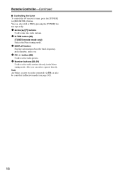
...page 142). 16 You can select a preset directly. Remote Controller-Continued ■ Controlling the tuner To control the AV receiver's tuner, press the [TUNER] (or [RECEIVER]) button. button (69) Used to select radio presets. 5 Number buttons (68, 69) Used to tune into radio... stations. 2 D.TUN button (68) (TUNER remote mode only) Selects the Direct tuning mode. 3 DISPLAY button Displays information about the band, frequency, preset number, and so on. 4 CH +/- Note: An Onkyo...
...page 142). 16 You can select a preset directly. Remote Controller-Continued ■ Controlling the tuner To control the AV receiver's tuner, press the [TUNER] (or [RECEIVER]) button. button (69) Used to select radio presets. 5 Number buttons (68, 69) Used to tune into radio... stations. 2 D.TUN button (68) (TUNER remote mode only) Selects the Direct tuning mode. 3 DISPLAY button Displays information about the band, frequency, preset number, and so on. 4 CH +/- Note: An Onkyo...

Owner Manual
Page 17
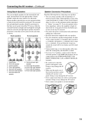
... on its position, the shape of the front left and right speakers (preferably as high as to the AV receiver's superb capabilities, you can enjoy Dolby Pro Logic IIx, DTS Neo:6, or Onkyo's original DSP listening modes. They significantly enhance the spatial experience. Position them at least 3.3 feet (100 cm) above ear...
... on its position, the shape of the front left and right speakers (preferably as high as to the AV receiver's superb capabilities, you can enjoy Dolby Pro Logic IIx, DTS Neo:6, or Onkyo's original DSP listening modes. They significantly enhance the spatial experience. Position them at least 3.3 feet (100 cm) above ear...

Owner Manual
Page 18
...one surround back speaker, connect it to PRE OUT: SW1. Level and distance can be set the speaker settings. Attaching the Speaker Labels The AV receiver's positive (+) speaker terminals are all black). You can do is unpowered and you're using banana plugs, tighten the speaker terminal before inserting the... speakers produce no sound at the same time. If your powered subwoofer, as shown. Connecting Powered Subwoofers Using a suitable cable, connect the AV receiver's PRE OUT: SW1, SW2 to an input on your subwoofer is to match the color of the speaker terminal. Connecting the AV...
...one surround back speaker, connect it to PRE OUT: SW1. Level and distance can be set the speaker settings. Attaching the Speaker Labels The AV receiver's positive (+) speaker terminals are all black). You can do is unpowered and you're using banana plugs, tighten the speaker terminal before inserting the... speakers produce no sound at the same time. If your powered subwoofer, as shown. Connecting Powered Subwoofers Using a suitable cable, connect the AV receiver's PRE OUT: SW1, SW2 to an input on your subwoofer is to match the color of the speaker terminal. Connecting the AV...
Owner Manual
Page 19
...8. Center speaker 4. Front high left speaker 10.Front high right speaker 11.Front wide left and right speakers. Doing so may damage the AV receiver. • Don't connect one cable to negative (-) terminals. Dipole speakers typically have contact with an impedance of between 4 and 16 ohms. ...to short the positive and negative wires. Surround back right speaker 9. Subwoofers 2. In other , as shown. Doing so may damage the AV receiver. • Don't connect more , but less than one speaker to the SURR L/R terminals. Dipole speakers output the same sound in protection circuit...
...8. Center speaker 4. Front high left speaker 10.Front high right speaker 11.Front wide left and right speakers. Doing so may damage the AV receiver. • Don't connect one cable to negative (-) terminals. Dipole speakers typically have contact with an impedance of between 4 and 16 ohms. ...to short the positive and negative wires. Surround back right speaker 9. Subwoofers 2. In other , as shown. Doing so may damage the AV receiver. • Don't connect more , but less than one speaker to the SURR L/R terminals. Dipole speakers output the same sound in protection circuit...
Owner Manual
Page 20
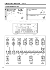
Connecting the AV receiver-Continued Connecting the Speaker Cables 1 Strip 1/2" to 5/8" (12 to 15 mm) of insulation from the ends of terminals. Front high right speaker Front wide right ...
Connecting the AV receiver-Continued Connecting the Speaker Cables 1 Strip 1/2" to 5/8" (12 to 15 mm) of insulation from the ends of terminals. Front high right speaker Front wide right ...
Owner Manual
Page 21
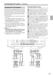
...terminal posts connect to the front speakers' tweeter terminals. • Once you've completed the bi-amping connections shown below and turned on the AV receiver, you must set the "Speakers Type(Front)" setting to "Bi-Amp" to the front speakers' woofer terminals. nect to enable biamping (see page ...only be used with speakers that link the Speakers' tweeter (high) and woofer (low) terminals. • Bi-amping can - Connecting the AV receiver-Continued Bi-amping the Front Speakers The FRONT L/R and SURR BACK/ZONE 3 L/R terminal posts can be used with front speakers and surround back ...
...terminal posts connect to the front speakers' tweeter terminals. • Once you've completed the bi-amping connections shown below and turned on the AV receiver, you must set the "Speakers Type(Front)" setting to "Bi-Amp" to the front speakers' woofer terminals. nect to enable biamping (see page ...only be used with speakers that link the Speakers' tweeter (high) and woofer (low) terminals. • Bi-amping can - Connecting the AV receiver-Continued Bi-amping the Front Speakers The FRONT L/R and SURR BACK/ZONE 3 L/R terminal posts can be used with front speakers and surround back ...

Owner Manual
Page 22
...injure yourself when using it with a commercially available outdoor AM antenna (see page 23). Once your AV receiver, TV, speaker cables, and power cords. Connecting the AV receiver-Continued Connecting Antenna This section explains how to connect the supplied indoor FM antenna and AM loop antenna, and...achieve the best possible reception. 2 Use thumbtacks or something similar to use only. 1 Attach the FM antenna, as possible from your AV receiver is for use only. 1 Assemble the AM loop antenna, inserting the tabs into the jack. If you cannot achieve good reception with ...
...injure yourself when using it with a commercially available outdoor AM antenna (see page 23). Once your AV receiver, TV, speaker cables, and power cords. Connecting the AV receiver-Continued Connecting Antenna This section explains how to connect the supplied indoor FM antenna and AM loop antenna, and...achieve the best possible reception. 2 Use thumbtacks or something similar to use only. 1 Attach the FM antenna, as possible from your AV receiver is for use only. 1 Assemble the AM loop antenna, inserting the tabs into the jack. If you cannot achieve good reception with ...
Owner Manual
Page 23
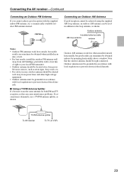
TV/FM antenna splitter To AV receiver To TV (or VCR) 23 Outdoor antenna must be obtained indoors by mounting horizontally above a window. Outdoor antenna Insulated antenna cable AM loop antenna Notes: &#... safety reasons, outdoor antenna should be used in accordance with the supplied indoor FM antenna, try a commercially available outdoor FM antenna instead. Connecting the AV receiver-Continued Connecting an Outdoor FM Antenna If you cannot achieve good reception with local regulations to prevent electrical shock hazards. Connecting an Outdoor AM Antenna...
TV/FM antenna splitter To AV receiver To TV (or VCR) 23 Outdoor antenna must be obtained indoors by mounting horizontally above a window. Outdoor antenna Insulated antenna cable AM loop antenna Notes: &#... safety reasons, outdoor antenna should be used in accordance with the supplied indoor FM antenna, try a commercially available outdoor FM antenna instead. Connecting the AV receiver-Continued Connecting an Outdoor FM Antenna If you cannot achieve good reception with local regulations to prevent electrical shock hazards. Connecting an Outdoor AM Antenna...


