Owner Manual
Page 2
... or the BSI mark on climate and placement of this instruction manual is fitted in memory power back-up system. IF THE H1 I Compatible remote control * XANTECH is exposed to a highly humid climate. 2 FOR U.S.A. Thank you to obtain optimum performance and listening enjoyment from 20 Hz to 20...to the terminal in your new Receiver. FOR EUROPEAN MODEL = = Declaration of the fuse. If in this manual for purchasing Me Onkyo TX-8511 Audio Video Control Rlteiier. Shoud the fuse need to be replaced please ensure that the replacement fuse has a rating of the memory during power failures...
... or the BSI mark on climate and placement of this instruction manual is fitted in memory power back-up system. IF THE H1 I Compatible remote control * XANTECH is exposed to a highly humid climate. 2 FOR U.S.A. Thank you to obtain optimum performance and listening enjoyment from 20 Hz to 20...to the terminal in your new Receiver. FOR EUROPEAN MODEL = = Declaration of the fuse. If in this manual for purchasing Me Onkyo TX-8511 Audio Video Control Rlteiier. Shoud the fuse need to be replaced please ensure that the replacement fuse has a rating of the memory during power failures...
Owner Manual
Page 4
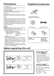
... wipe the front and rear panels and the cabinet with a switch that of copyrighted material for other than personal use for your Onkyo authorized service station. 4. Recording Copyright Recording of the unit. • The power does not shut off completely by just turning ... Please set this number. 2. Care From time to con- Setting the tuning sir frequency(W0rldwidemodel only) The worldwide model is not user-serviceable. oGoo Remote control RC-329S (1) Battery (size AA, R6, or UM-3) (2) et AM loop antenna (1) T-shaped FM antenna (1) 0 (Worldwide and some other ...
... wipe the front and rear panels and the cabinet with a switch that of copyrighted material for other than personal use for your Onkyo authorized service station. 4. Recording Copyright Recording of the unit. • The power does not shut off completely by just turning ... Please set this number. 2. Care From time to con- Setting the tuning sir frequency(W0rldwidemodel only) The worldwide model is not user-serviceable. oGoo Remote control RC-329S (1) Battery (size AA, R6, or UM-3) (2) et AM loop antenna (1) T-shaped FM antenna (1) 0 (Worldwide and some other ...
Owner Manual
Page 5
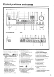
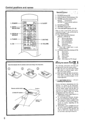
... Monitor) indicator c. TUNED indicator j. Control positions and names Other than USA & Canadian model 1 2 3 4 5 6' 7 ONSVi r0 ralat, CORDS /pad .r•Va Ira 4.0. 0•100, MK 0 8 9 10 11 12 13 14 Is PIO u CO i Ttit!) ) 4.1•04.400 TX 5,, 22 21 USA and Canadian model ... OFF STEREO ...-GrE m"i2tf1r\1iu-i1l-\t"r?.m\t/I . Front, panel sr 317147.07 1. POWER (or SYSTEM) switch 11 2 1 2. MR OFF button [261 4. Remote sensor 161 6. DISPLAY button [191 7. 44 DOWN, UP IP- TUNING buttons [15] 8. 1)1 RECI"l'UNING button [151 9. GROUP button [16, 17] 10...
... Monitor) indicator c. TUNED indicator j. Control positions and names Other than USA & Canadian model 1 2 3 4 5 6' 7 ONSVi r0 ralat, CORDS /pad .r•Va Ira 4.0. 0•100, MK 0 8 9 10 11 12 13 14 Is PIO u CO i Ttit!) ) 4.1•04.400 TX 5,, 22 21 USA and Canadian model ... OFF STEREO ...-GrE m"i2tf1r\1iu-i1l-\t"r?.m\t/I . Front, panel sr 317147.07 1. POWER (or SYSTEM) switch 11 2 1 2. MR OFF button [261 4. Remote sensor 161 6. DISPLAY button [191 7. 44 DOWN, UP IP- TUNING buttons [15] 8. 1)1 RECI"l'UNING button [151 9. GROUP button [16, 17] 10...
Owner Manual
Page 6
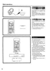
...will help you get optimal use the following buttons. 3. Placing this unit away from the remote control. • Place this unit behind such a door may prevent proper remote control operation. CD POWER SLEEP INPUT SELECTOR n :fE nl • . :l. 1! INI... CD changer Using the remote contrrir- fY±-OCJ-W1L75n 1=1 A CI CI (= 4se VOLUME C] ONKYO REMOTE CONTROLLER RC-MS 6. bt DECK4 •,.. MUTING 8. INPUT SELECTOR 3. POWER 2. O O (-3O Remote control sensor STAND-BY indicator 30' 30* TX-8511 approx. 5 m (16 feet) 6 RernOte'COntrol' ' 1. iNnirorM?•...
...will help you get optimal use the following buttons. 3. Placing this unit away from the remote control. • Place this unit behind such a door may prevent proper remote control operation. CD POWER SLEEP INPUT SELECTOR n :fE nl • . :l. 1! INI... CD changer Using the remote contrrir- fY±-OCJ-W1L75n 1=1 A CI CI (= 4se VOLUME C] ONKYO REMOTE CONTROLLER RC-MS 6. bt DECK4 •,.. MUTING 8. INPUT SELECTOR 3. POWER 2. O O (-3O Remote control sensor STAND-BY indicator 30' 30* TX-8511 approx. 5 m (16 feet) 6 RernOte'COntrol' ' 1. iNnirorM?•...

Owner Manual
Page 7
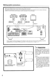
... instruction manual of each pair of other component installed with an R I connector. ROM, aunt, ORR,. Making system connections ME') Turntable O PHONO 0 OUT Li Refer to control Onkyo turntables. • An R I remote control cable equipped with 1/8" (3.5 mm) mini jacks is included with any other components, connect the remote control cable as shown at the left channel.
... instruction manual of each pair of other component installed with an R I connector. ROM, aunt, ORR,. Making system connections ME') Turntable O PHONO 0 OUT Li Refer to control Onkyo turntables. • An R I remote control cable equipped with 1/8" (3.5 mm) mini jacks is included with any other components, connect the remote control cable as shown at the left channel.
Owner Manual
Page 8
... not exceed the capacity that is printed on the rear panel above the AC outlets. • (For the European and worldwide models) The remote control cannot be interference between the 'I VIDEO IN VIDEO OUT AUDIO IN AUDIO OUT VIDEO IN 0400.4 Wlf iG i ts Irt.004•00...NOTE: • The shape, number and total capacity of the AC outlets may differ according to Connecting anten»ax on the front panel and remote control. On each component when making connections. l • Dm_orLmie. ■ ONICY0•n•a WOW Vi0t0 mi 0t044. Making system connections Refer to the...
... not exceed the capacity that is printed on the rear panel above the AC outlets. • (For the European and worldwide models) The remote control cannot be interference between the 'I VIDEO IN VIDEO OUT AUDIO IN AUDIO OUT VIDEO IN 0400.4 Wlf iG i ts Irt.004•00...NOTE: • The shape, number and total capacity of the AC outlets may differ according to Connecting anten»ax on the front panel and remote control. On each component when making connections. l • Dm_orLmie. ■ ONICY0•n•a WOW Vi0t0 mi 0t044. Making system connections Refer to the...
Owner Manual
Page 12
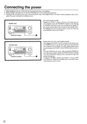
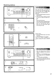
...AC outlet puts the unit in stand-by status (the STAND-BY indicator is pressed again, the unit returns to operate the TX-8511 if the SYSTEM switch is lit). The remote control cannot be used to the stand-by status (the STAND-BY indicator is fully turned counterclockwise. • Turning on this ... knob is lit) and power-on status (the display will light up the display. Pressing the POWER switch turns on the remote control switches the TX-85I I . Pressing the SYSTEM switch on the TX-851 I to set it to OFF turns off the unit. (When the SYSTEM switch is set to OFF, only a...
...AC outlet puts the unit in stand-by status (the STAND-BY indicator is pressed again, the unit returns to operate the TX-8511 if the SYSTEM switch is lit). The remote control cannot be used to the stand-by status (the STAND-BY indicator is fully turned counterclockwise. • Turning on this ... knob is lit) and power-on status (the display will light up the display. Pressing the POWER switch turns on the remote control switches the TX-85I I . Pressing the SYSTEM switch on the TX-851 I to set it to OFF turns off the unit. (When the SYSTEM switch is set to OFF, only a...
Owner Manual
Page 13
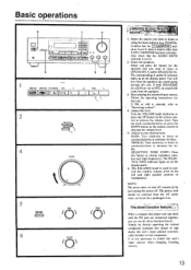
...not lit. 2. Confirm that component. If both SPEAKERS (A and B) are connected together, you wish to listen to attenuate the tre- remote control to OFF, no sound will hear from the AC outlet when not in use the direct function feature. The power cord should be removed... Press this unit's input selector automatically switches to clearly reproduce ultralow and -high frequencies. The corresponding A and/or B indicator lights up on the remote control to TREBLE 0 109 5. When a compact disc player and tape deck with the R I jack are set to decrease the volume level. 5. ...
...not lit. 2. Confirm that component. If both SPEAKERS (A and B) are connected together, you wish to listen to attenuate the tre- remote control to OFF, no sound will hear from the AC outlet when not in use the direct function feature. The power cord should be removed... Press this unit's input selector automatically switches to clearly reproduce ultralow and -high frequencies. The corresponding A and/or B indicator lights up on the remote control to TREBLE 0 109 5. When a compact disc player and tape deck with the R I jack are set to decrease the volume level. 5. ...
Owner Manual
Page 14
... off . CanCelling the SLEEP setting The timeL will be controlled with your TX-85I I. 1. pvf-.7 T. You can be cancelled if you: • presrthe SLEEP button until the desired time has been reached. The muting function will flash. To operate this function, use the remote control supplied with the SPEAKERS A/ B buttons. RC-329S a/ Er c c o LL1... temporarily switches off the system after which you would like to listen to 90 minutes. The sleep timer can be switched off then on the remote control.
... off . CanCelling the SLEEP setting The timeL will be controlled with your TX-85I I. 1. pvf-.7 T. You can be cancelled if you: • presrthe SLEEP button until the desired time has been reached. The muting function will flash. To operate this function, use the remote control supplied with the SPEAKERS A/ B buttons. RC-329S a/ Er c c o LL1... temporarily switches off the system after which you would like to listen to 90 minutes. The sleep timer can be switched off then on the remote control.
Owner Manual
Page 17
Main unit 1. Input the memory number you want is reached, scanning will stop. or Press the SCAN button. Remote control 1. After the last number of GROUP C is found, press the SCAN button again and scanning will restart at GROUP A. 1=1 o • I :11 .027.loCO2 .,..22.001.; ... source by using the number buttons. c> Val lieliliMetStatiO 1. Press the FM MUTE/MODE button while holding down the MEMORY button. -" will be shown on the remote control. celled, the memory location can -
Main unit 1. Input the memory number you want is reached, scanning will stop. or Press the SCAN button. Remote control 1. After the last number of GROUP C is found, press the SCAN button again and scanning will restart at GROUP A. 1=1 o • I :11 .027.loCO2 .,..22.001.; ... source by using the number buttons. c> Val lieliliMetStatiO 1. Press the FM MUTE/MODE button while holding down the MEMORY button. -" will be shown on the remote control. celled, the memory location can -
Owner Manual
Page 23
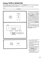
...cannot be lit; The source signal can he used for recording, press either the TAPE-2 button on the remote control or the TAI'E-2 MONITOR button on the rear panel of the TX-8511. 2. Follow the operating instructions for a few seconds, light up . 4. T-2 MONITOR Playback Recording Playback ...graphic equalizer to the equalizer. 23 TAPES MONITOR B TX-8511 AMP. Monitoring during recording. If the 3-head tape deck connected to the TAPE-2 connectors is used to monitor the recording. Press the TAPE-2 button on the remote control or the TAPE-2 MONITOR button on the main unit ...
...cannot be lit; The source signal can he used for recording, press either the TAPE-2 button on the remote control or the TAI'E-2 MONITOR button on the rear panel of the TX-8511. 2. Follow the operating instructions for a few seconds, light up . 4. T-2 MONITOR Playback Recording Playback ...graphic equalizer to the equalizer. 23 TAPES MONITOR B TX-8511 AMP. Monitoring during recording. If the 3-head tape deck connected to the TAPE-2 connectors is used to monitor the recording. Press the TAPE-2 button on the remote control or the TAPE-2 MONITOR button on the main unit ...
Owner Manual
Page 24
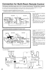
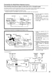
... equipped with Onkyo R I jacks Components mounted in the main room. or Canada model (Xantechm' Multiple-Room systems) Do not plug in the connection diagram below. Connecting components equipped with OnkyoRl jacks 3. (Ecm) itter n MAIN ROOM 5. A. Remote Sensor\ 2. Components(d) TX-8511 I Speaker A (Main room) \ 7-\ \ TX-8511 7 , Speaker A (Main room) 3. A (Main room) Speaker A (Main room) Power supply' Remote control Remote Sensor...
... equipped with Onkyo R I jacks Components mounted in the main room. or Canada model (Xantechm' Multiple-Room systems) Do not plug in the connection diagram below. Connecting components equipped with OnkyoRl jacks 3. (Ecm) itter n MAIN ROOM 5. A. Remote Sensor\ 2. Components(d) TX-8511 I Speaker A (Main room) \ 7-\ \ TX-8511 7 , Speaker A (Main room) 3. A (Main room) Speaker A (Main room) Power supply' Remote control Remote Sensor...
Owner Manual
Page 25
... A -',/ Speaker A (Main room) / f* (Main room) 7 -\ \`. SUB ROOM Remote control in3. Connecting components not equippped with Onkyo R I TX-8511 \ Spearke7 (Main room) 1/ . Components(b) Remote sensor Remote control- - Connect the components (b) to the TX -8511. 5. Install Remote Emitter 11E-50 (AC) so that its sensor is directed toward these components. or Canada model Do not plug in steps 2 through 0 be sure to ...
... A -',/ Speaker A (Main room) / f* (Main room) 7 -\ \`. SUB ROOM Remote control in3. Connecting components not equippped with Onkyo R I TX-8511 \ Spearke7 (Main room) 1/ . Components(b) Remote sensor Remote control- - Connect the components (b) to the TX -8511. 5. Install Remote Emitter 11E-50 (AC) so that its sensor is directed toward these components. or Canada model Do not plug in steps 2 through 0 be sure to ...
Owner Manual
Page 26
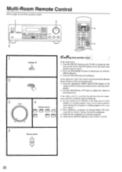
...the remote control to check whether the component is not lit. 5 Remote control A VOLUME Mil V 26 nt r±. In the sub-room, direct the remote control toward that component. • Check that the components are correctly connected. • Check that the emitter is directed toward the Remote Sensor (Onkyo ... 1. i o-n • a .6-o- (±) on the remote control to select your desired source and start operating it is lit, the multi-room system cannot be controlled, check the following: • Use the controls On the TX-8511 in the main room to check whether it . 5. g from...
...the remote control to check whether the component is not lit. 5 Remote control A VOLUME Mil V 26 nt r±. In the sub-room, direct the remote control toward that component. • Check that the components are correctly connected. • Check that the emitter is directed toward the Remote Sensor (Onkyo ... 1. i o-n • a .6-o- (±) on the remote control to select your desired source and start operating it is lit, the multi-room system cannot be controlled, check the following: • Use the controls On the TX-8511 in the main room to check whether it . 5. g from...
Owner Manual
Page 27
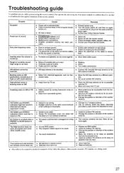
Troubleshooting guide If a problem occurs, while you are using the remote control, first operate the unit using, the front panel controls to confirm that it again. • Contact your Onkyo Service Center. Hum, low-frequency noise • Poor or no input ground. • Poor or no sound Cause ... • The placement of the audio connection cables on AM (particularly conspicuous at night or with the remote control. • Check connection cables, speaker cables, etc. • Contact your Onkyo Service Center. • Switch off. • Switch off , and then on FM. Howling when ...
Troubleshooting guide If a problem occurs, while you are using the remote control, first operate the unit using, the front panel controls to confirm that it again. • Contact your Onkyo Service Center. Hum, low-frequency noise • Poor or no input ground. • Poor or no sound Cause ... • The placement of the audio connection cables on AM (particularly conspicuous at night or with the remote control. • Check connection cables, speaker cables, etc. • Contact your Onkyo Service Center. • Switch off. • Switch off , and then on FM. Howling when ...

Owner Manual
Page 28
...ei!ht: 435 x 150 x 322 mm 17-1/8"x 5-7/8" x 12-11/16" 8.9 kg. 19.6 lbs REMOTE CONTROL RC-329S Transmitter: Infrared Signal range: Power supply: Approx. 5 meters. 16 ft. N.T., HONG KONG Tel: 852.2429-3118 Fax: 852-2428-9039 ONKYO httpiNJHewOMwE.ePnAkGyEoI.m.fp/ 107960 Specifications AMPLIFIER SECTION Power Output: USA & Canadian models: 100 Watts... 0.08% THD. Frequency Response: 20 to 30.000 Hz. ±1 dB RIAA Deviation: 20 to 20.000 Hz. ±0.8 dB Tone Control: BASS: ±10 dB at 100 Hz TREBLE: ±I0 dB at 8 ohms, both channels driven from 20 Hz to Noise Ratio:...
...ei!ht: 435 x 150 x 322 mm 17-1/8"x 5-7/8" x 12-11/16" 8.9 kg. 19.6 lbs REMOTE CONTROL RC-329S Transmitter: Infrared Signal range: Power supply: Approx. 5 meters. 16 ft. N.T., HONG KONG Tel: 852.2429-3118 Fax: 852-2428-9039 ONKYO httpiNJHewOMwE.ePnAkGyEoI.m.fp/ 107960 Specifications AMPLIFIER SECTION Power Output: USA & Canadian models: 100 Watts... 0.08% THD. Frequency Response: 20 to 30.000 Hz. ±1 dB RIAA Deviation: 20 to 20.000 Hz. ±0.8 dB Tone Control: BASS: ±10 dB at 100 Hz TREBLE: ±I0 dB at 8 ohms, both channels driven from 20 Hz to Noise Ratio:...


