Owner Manual
Page 1
OOO European models Other models CONTENT PFreetuaruens.p.-n...s-=-,.-..1.?::- ., „--,-, Sr-LiPlp-9fpiogor&e'Fofasp-r,e;,.;r.4a.--.tp.n,4-s.a-s-g.Fo,.A'.4-.t-.4ih_gi,-s-er-l---e,,•:j;,l.,,i,n*,,:.s-til ,::?..k:4r-4 ,... -; -- 491.4%46? ..,..,..v... ,444.--*Zi...krico-,.„",_ U0141)0SitiOnS'anovnaites 21--4- onnnectinanntecnonna- APEallt0 2 pppec4onf:gr;:,._ pn-:gropjzt 2•uRltei4iiZio6ofe-n.C.Ti. ONKYO. t 54 z:. - , 7 ..= roubleshooting - EaliOhe:441-011 -24.4t-,`-- 7''';',10-C428 TX-8511 Audio Video Control Receiver Instruction...
OOO European models Other models CONTENT PFreetuaruens.p.-n...s-=-,.-..1.?::- ., „--,-, Sr-LiPlp-9fpiogor&e'Fofasp-r,e;,.;r.4a.--.tp.n,4-s.a-s-g.Fo,.A'.4-.t-.4ih_gi,-s-er-l---e,,•:j;,l.,,i,n*,,:.s-til ,::?..k:4r-4 ,... -; -- 491.4%46? ..,..,..v... ,444.--*Zi...krico-,.„",_ U0141)0SitiOnS'anovnaites 21--4- onnnectinanntecnonna- APEallt0 2 pppec4onf:gr;:,._ pn-:gropjzt 2•uRltei4iiZio6ofe-n.C.Ti. ONKYO. t 54 z:. - , 7 ..= roubleshooting - EaliOhe:441-011 -24.4t-,`-- 7''';',10-C428 TX-8511 Audio Video Control Receiver Instruction...
Owner Manual
Page 2
...connected to the grounding system of the building, as close to a highly humid climate. 2 FOR U.S.A. YAMAZOE ONKYO EUROPE ELECTRONICS GMBH zmiumi ATTENTION FOR BRITISH MODEL Replacement and mounting of an AC plug on climate and placement of cable entry as follows: The wire which...not correspond with the coloured markings identifying the terminals in the plug which provides guidelines for purchasing Me Onkyo TX-8511 Audio Video Control Rlteiier. PTY, RT, TP (European and some other models only) I Direct access tuning II Motor-driven, precision volume control III Headphone jack p Audio ...
...connected to the grounding system of the building, as close to a highly humid climate. 2 FOR U.S.A. YAMAZOE ONKYO EUROPE ELECTRONICS GMBH zmiumi ATTENTION FOR BRITISH MODEL Replacement and mounting of an AC plug on climate and placement of cable entry as follows: The wire which...not correspond with the coloured markings identifying the terminals in the plug which provides guidelines for purchasing Me Onkyo TX-8511 Audio Video Control Rlteiier. PTY, RT, TP (European and some other models only) I Direct access tuning II Motor-driven, precision volume control III Headphone jack p Audio ...
Owner Manual
Page 4
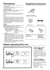
... the voltage of the power supply in your Onkyo authorized service station. 4. Do not use only with the power supply voltage of the copyright holder. 3. OTHER USA / f•t Setting the voZage selector (worldwide model.only) I 20V, 60Hz Worldwide model: AC 720-230V/120V switehable. 50/60Hz ...your area: 220 - 230 V or 120 V. 2, If .the setting on , contact your area before plugging in the unit. (See below.) Models without permission of the region where they are sold. Power WARNING BEFORE PLUGGING IN THE UNIT FOR THE FIRST TIME, READ THE FOLLOWING SECTION CAREFULLY...
... the voltage of the power supply in your Onkyo authorized service station. 4. Do not use only with the power supply voltage of the copyright holder. 3. OTHER USA / f•t Setting the voZage selector (worldwide model.only) I 20V, 60Hz Worldwide model: AC 720-230V/120V switehable. 50/60Hz ...your area: 220 - 230 V or 120 V. 2, If .the setting on , contact your area before plugging in the unit. (See below.) Models without permission of the region where they are sold. Power WARNING BEFORE PLUGGING IN THE UNIT FOR THE FIRST TIME, READ THE FOLLOWING SECTION CAREFULLY...
Owner Manual
Page 5
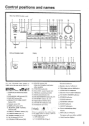
... on the surface of the display which is making it difficult to the page number listedin [ ]. it . RDS indicator (Only for European and some other models) 14. DISPLAY button [191 7. 44 DOWN, UP IP- TUNING buttons [15] 8. 1)1 RECI"l'UNING button [151 9. T-2 MONITOR (Tape-2 Monitor) indicator c. ... ralat, CORDS /pad .r•Va Ira 4.0. 0•100, MK 0 8 9 10 11 12 13 14 Is PIO u CO i Ttit!) ) 4.1•04.400 TX 5,, 22 21 USA and Canadian model 20 19 18 17 16 15 Display a d e f ah i k I -APRRR STEREO MODE ''•MOOE [ULM MU WIN I \tp\i. 11/ GROUP ABC SLEEP...
... on the surface of the display which is making it difficult to the page number listedin [ ]. it . RDS indicator (Only for European and some other models) 14. DISPLAY button [191 7. 44 DOWN, UP IP- TUNING buttons [15] 8. 1)1 RECI"l'UNING button [151 9. T-2 MONITOR (Tape-2 Monitor) indicator c. ... ralat, CORDS /pad .r•Va Ira 4.0. 0•100, MK 0 8 9 10 11 12 13 14 Is PIO u CO i Ttit!) ) 4.1•04.400 TX 5,, 22 21 USA and Canadian model 20 19 18 17 16 15 Display a d e f ah i k I -APRRR STEREO MODE ''•MOOE [ULM MU WIN I \tp\i. 11/ GROUP ABC SLEEP...
Owner Manual
Page 8
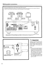
...making connections. l • Dm_orLmie. ■ ONICY0•n•a WOW Vi0t0 mi 0t044. We do not exceed the capacity that other than USA and Canadian models) on page 10, 110 4-- NOTE: • The shape, number and total capacity of the AC outlets may differ according to the instruction manual of a... switch on the front panel is set to Connecting anten»ax on the front panel and remote control. Making system connections Refer to the model and the area where the unit is purchased. VDP (VIDEO-1) = 000 VCR (VIDEO-2) OE= TV/Monitor VIDEO OUT AUDIO OUT I I 'V and this unit...
...making connections. l • Dm_orLmie. ■ ONICY0•n•a WOW Vi0t0 mi 0t044. We do not exceed the capacity that other than USA and Canadian models) on page 10, 110 4-- NOTE: • The shape, number and total capacity of the AC outlets may differ according to the instruction manual of a... switch on the front panel is set to Connecting anten»ax on the front panel and remote control. Making system connections Refer to the model and the area where the unit is purchased. VDP (VIDEO-1) = 000 VCR (VIDEO-2) OE= TV/Monitor VIDEO OUT AUDIO OUT I I 'V and this unit...

Owner Manual
Page 9
... at the same time. 0 0 0 O OO +- - R L 0 0 0 R L 9 Making system connections USA and Canadian models to the impedance of the speakers used, set the SPEAKER INPEDANCE • SELECTOR on the rear panel as shown iii the table. t..ppeakrym ... wire. 3. If the DC resistance of "Speaker impedance". LJ SPEAKER IMPEDANCE SELECTOR [o A OR B: L A OR B: 8 OHMS MINJSPEAKER 4 OHMS MINJSPEAKER A+B: 8 OHMS MINJSPEAKER Other models CAUTION: SPEAKER IMPEDANCE A or B: 4 ohms min./speaker A+ B : 8 ohms min./speaker O SPEAKER A 0.4 SPEAKER B R O SPEAKER A SPEAKER B O 00 000000 000000...
... at the same time. 0 0 0 O OO +- - R L 0 0 0 R L 9 Making system connections USA and Canadian models to the impedance of the speakers used, set the SPEAKER INPEDANCE • SELECTOR on the rear panel as shown iii the table. t..ppeakrym ... wire. 3. If the DC resistance of "Speaker impedance". LJ SPEAKER IMPEDANCE SELECTOR [o A OR B: L A OR B: 8 OHMS MINJSPEAKER 4 OHMS MINJSPEAKER A+B: 8 OHMS MINJSPEAKER Other models CAUTION: SPEAKER IMPEDANCE A or B: 4 ohms min./speaker A+ B : 8 ohms min./speaker O SPEAKER A 0.4 SPEAKER B R O SPEAKER A SPEAKER B O 00 000000 000000...
Owner Manual
Page 10
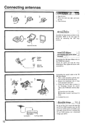
... and keep it into the slot. C) Insert the end of the cable. (i) Use pliers to the 75/ 300 ohm adaptor I . Directional linkage type splitter To TX-8511 To TV (or VCR) DIrectional linkage Do not use a directional linkage type splitter. 1'0 et. Slit B fi4-44eAi • Mill -14 -;0040 rel- pers ...outwards and remove the cover. 2. Connect the coaxial cable to the 75/300 ohm adaptor Loosen the screws and wrap the wires around them. models), , Connecting the 300 ohm ribbon wire to the 75/300 ohm antenna adaptor. Insert into slit C. 3. If you must use a common FM/ TV (...
... and keep it into the slot. C) Insert the end of the cable. (i) Use pliers to the 75/ 300 ohm adaptor I . Directional linkage type splitter To TX-8511 To TV (or VCR) DIrectional linkage Do not use a directional linkage type splitter. 1'0 et. Slit B fi4-44eAi • Mill -14 -;0040 rel- pers ...outwards and remove the cover. 2. Connect the coaxial cable to the 75/300 ohm adaptor Loosen the screws and wrap the wires around them. models), , Connecting the 300 ohm ribbon wire to the 75/300 ohm antenna adaptor. Insert into slit C. 3. If you must use a common FM/ TV (...
Owner Manual
Page 12
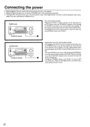
... trade properly. • Before turning on the power, be sure that the VOLUME knob is fully turned counterclockwise. • Turning on a different circuit. and Canadian models: After plugging the TX-8511's power cord into an AC outlet puts the unit in stand-by status. puters. POWER switch • STAND-BY indicator 000 U.S.
... trade properly. • Before turning on the power, be sure that the VOLUME knob is fully turned counterclockwise. • Turning on a different circuit. and Canadian models: After plugging the TX-8511's power cord into an AC outlet puts the unit in stand-by status. puters. POWER switch • STAND-BY indicator 000 U.S.
Owner Manual
Page 18
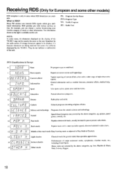
...information shown at the right is because characters are available. SPURT 4 News reports Current affairs Information Sport Reports on the display of the TX-8511 may not be correctly displayed by the radio station. II I , un Lr It.t I I ' PI Light classics Serious classics ... . Jazz. RDS provides you can choose a station broadcasting your favorite category of music or other models) RDS reception is RDS? NOTE: In. General information such as the ones broadcast by the TX-851I. quizzes, panel games, comedy, etc. Rhythm & Blues, Folk, Country, Reggae. 18 some...
...information shown at the right is because characters are available. SPURT 4 News reports Current affairs Information Sport Reports on the display of the TX-8511 may not be correctly displayed by the radio station. II I , un Lr It.t I I ' PI Light classics Serious classics ... . Jazz. RDS provides you can choose a station broadcasting your favorite category of music or other models) RDS reception is RDS? NOTE: In. General information such as the ones broadcast by the TX-851I. quizzes, panel games, comedy, etc. Rhythm & Blues, Folk, Country, Reggae. 18 some...
Owner Manual
Page 19
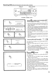
Receiving RDS (Only for example. Use the TUNING UP/DOWN buttons to select another program type (PTY) (for European and some other models) DISPLAY SCAN PTY/TP ===1 • F 00 1=1=1 L I r I l I l l ° 0 0 0 DOWN TUNING UP ► 1 P1..1• t__1 1 I It 2 YP 01- 11- Press the SCAN button to receive the ...
Receiving RDS (Only for example. Use the TUNING UP/DOWN buttons to select another program type (PTY) (for European and some other models) DISPLAY SCAN PTY/TP ===1 • F 00 1=1=1 L I r I l I l l ° 0 0 0 DOWN TUNING UP ► 1 P1..1• t__1 1 I It 2 YP 01- 11- Press the SCAN button to receive the ...
Owner Manual
Page 20
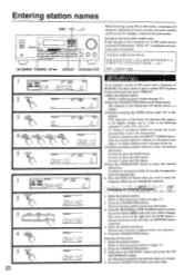
...button until "O" is replaced with a frequency of 89.50 MHz has been stored in preset number 2CH of letters, numbers and some other models only: If you attempt to represent the station name. To delete a character, press the DIRECT TUNING button. l'ress the CIIARACTER button. ... 17.) 2.Press the CHARACTER button on page 17.) 2. After the selected character is not pressed within 16 seconds, the operation will be given the name "ONKYO". All characters entered for an FM station broadcasting RDS information, "RDS...PS" is pressed. 4. i, Ili t_liqi% tit I SP UM{ A i - ...
...button until "O" is replaced with a frequency of 89.50 MHz has been stored in preset number 2CH of letters, numbers and some other models only: If you attempt to represent the station name. To delete a character, press the DIRECT TUNING button. l'ress the CIIARACTER button. ... 17.) 2.Press the CHARACTER button on page 17.) 2. After the selected character is not pressed within 16 seconds, the operation will be given the name "ONKYO". All characters entered for an FM station broadcasting RDS information, "RDS...PS" is pressed. 4. i, Ili t_liqi% tit I SP UM{ A i - ...
Owner Manual
Page 24
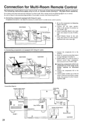
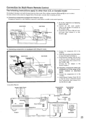
...Components(b) / \ \ s.-- .r . Install Remote Sensor in the connection diagram below to the TX-8511. (0) 4. Connecting components not equipped with Onkyo R I jacks Components mounted in the main room. Components(d) TX-8511 I Speaker A (Main room) \ 7-\ \ TX-8511 7 , Speaker A (Main room) 3. A (Main room) Speaker A (Main room) ... should be sure to the TX-8511. (tD) ■ Operating components which are positioned out of the range of section A. 3. or Canada model (Xantechm' Multiple-Room systems) Do not plug in SPEAKERS B TX-8511 24 Connecting block Emitter U ...
...Components(b) / \ \ s.-- .r . Install Remote Sensor in the connection diagram below to the TX-8511. (0) 4. Connecting components not equipped with Onkyo R I jacks Components mounted in the main room. Components(d) TX-8511 I Speaker A (Main room) \ 7-\ \ TX-8511 7 , Speaker A (Main room) 3. A (Main room) Speaker A (Main room) ... should be sure to the TX-8511. (tD) ■ Operating components which are positioned out of the range of section A. 3. or Canada model (Xantechm' Multiple-Room systems) Do not plug in SPEAKERS B TX-8511 24 Connecting block Emitter U ...
Owner Manual
Page 25
... have been made. then connect it to the TX-8511. 2. or Canada model Do not plug in steps 2 through 0 be connected as shown in the sub-room. Connecting components equipped with Onkyo R I jacks Components mounted in a rack should be sure to enable remote control operation. Onkyo components (a) TX-8511 L Speaker A -',/ Speaker A (Main room) / f* (Main room) 7 -\ \`. then connect...
... have been made. then connect it to the TX-8511. 2. or Canada model Do not plug in steps 2 through 0 be connected as shown in the sub-room. Connecting components equipped with Onkyo R I jacks Components mounted in a rack should be sure to enable remote control operation. Onkyo components (a) TX-8511 L Speaker A -',/ Speaker A (Main room) / f* (Main room) 7 -\ \`. then connect...
Owner Manual
Page 27
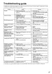
...occurs, while you are using the remote control, first operate the unit using, the front panel controls to confirm that it again. • Contact your Onkyo Service Center. • Switch off. • Switch off . • Noise from automobile ignition. • Move antenna as far as possible from ... an antenna which has better directivity and select a point where the distortion is bad. The RDS function does not work. (European and some other models only) • Station is too strong. • Multiple reflection of the radio waves because of tall buildings or mountains. • Station is ...
...occurs, while you are using the remote control, first operate the unit using, the front panel controls to confirm that it again. • Contact your Onkyo Service Center. • Switch off. • Switch off . • Noise from automobile ignition. • Move antenna as far as possible from ... an antenna which has better directivity and select a point where the distortion is bad. The RDS function does not work. (European and some other models only) • Station is too strong. • Multiple reflection of the radio waves because of tall buildings or mountains. • Station is ...

Owner Manual
Page 28
.... at 1.000 Hz. 0.5% THD. N.T., HONG KONG Tel: 852.2429-3118 Fax: 852-2428-9039 ONKYO httpiNJHewOMwE.ePnAkGyEoI.m.fp/ 107960 Specifications AMPLIFIER SECTION Power Output: USA & Canadian models: 100 Watts per channel. VIDEO-1.2): 150 mV, 50 kohms Video (VIDEO-1. 2): Vp-p. 75 ohms Output... Level and Impedance: Rec out (TAPE-I . 223 Fling Fong Road. SN 293423658 ONKYO CORPORATION Sales & Product Planning Div. : 2.1, ...
.... at 1.000 Hz. 0.5% THD. N.T., HONG KONG Tel: 852.2429-3118 Fax: 852-2428-9039 ONKYO httpiNJHewOMwE.ePnAkGyEoI.m.fp/ 107960 Specifications AMPLIFIER SECTION Power Output: USA & Canadian models: 100 Watts per channel. VIDEO-1.2): 150 mV, 50 kohms Video (VIDEO-1. 2): Vp-p. 75 ohms Output... Level and Impedance: Rec out (TAPE-I . 223 Fling Fong Road. SN 293423658 ONKYO CORPORATION Sales & Product Planning Div. : 2.1, ...


