GS716Tv2/GS724Tv3 Hardware manual
Page 7
... want the power of Gigabit connectivity to eliminate bottlenecks, boost performance, and increase productivity. The switch's management features include configuration for port and switch information, VLAN for traffic control, port trunking for the following NETGEAR Smart Switches: • GS716T - The NETGEAR Smart Switch is for increased bandwidth, and Class of the network. This product offers support for the observation...
... want the power of Gigabit connectivity to eliminate bottlenecks, boost performance, and increase productivity. The switch's management features include configuration for port and switch information, VLAN for traffic control, port trunking for the following NETGEAR Smart Switches: • GS716T - The NETGEAR Smart Switch is for increased bandwidth, and Class of the network. This product offers support for the observation...
GS716Tv2/GS724Tv3 Hardware manual
Page 8
... and auto-negotiating capabilities for traffic prioritization. Initial discovery of the switch on the network requires the Smart Wizard Discovery program, a utility that have a mix of Ethernet, Fast Ethernet, or Gigabit Ethernet devices. In addition, all ports to the Combo ports are...offers low latency for fiber connections using SFP GBIC modules. Combo ports are supported: • 1000BASE-SX • 1000BASE-LX • 100BASE-FX • The devices support full NETGEAR Smart Switch functionality. • The devices provide full compatibility with two physical connections, ...
... and auto-negotiating capabilities for traffic prioritization. Initial discovery of the switch on the network requires the Smart Wizard Discovery program, a utility that have a mix of Ethernet, Fast Ethernet, or Gigabit Ethernet devices. In addition, all ports to the Combo ports are...offers low latency for fiber connections using SFP GBIC modules. Combo ports are supported: • 1000BASE-SX • 1000BASE-LX • 100BASE-FX • The devices support full NETGEAR Smart Switch functionality. • The devices provide full compatibility with two physical connections, ...
GS716Tv2/GS724Tv3 Hardware manual
Page 9
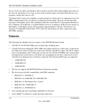
Reset PWR ® ProSafe 24 Port Gigabit Smart Switch 1 3 5 7 9 11 13 15 17 19 21 23 LINK/ACT SPD Green (1000M) Yellow (100M) FDX 2 4 6 8 10 12 14 16 18 20 22 24 LINK/ACT .... • Half-duplex back-pressure control. • Per port LEDs, System LEDs. • Standard 1U high, rack-mountable 17-inch chassis. • Fan speed control supported. Package Contents Figure 1-1 shows the package contents of the NETGEAR GS716T and GS724T Series Smart Switch.
Reset PWR ® ProSafe 24 Port Gigabit Smart Switch 1 3 5 7 9 11 13 15 17 19 21 23 LINK/ACT SPD Green (1000M) Yellow (100M) FDX 2 4 6 8 10 12 14 16 18 20 22 24 LINK/ACT .... • Half-duplex back-pressure control. • Per port LEDs, System LEDs. • Standard 1U high, rack-mountable 17-inch chassis. • Fan speed control supported. Package Contents Figure 1-1 shows the package contents of the NETGEAR GS716T and GS724T Series Smart Switch.
GS716Tv2/GS724Tv3 Hardware manual
Page 10
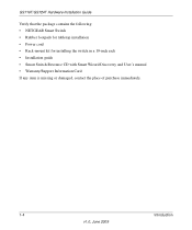
GS716T/GS724T Hardware Installation Guide Verify that the package contains the following: • NETGEAR Smart Switch • Rubber footpads for tabletop installation • Power cord • Rack-mount kit for installing the switch in a 19-inch rack • Installation guide • Smart Switch Resource CD with Smart Wizard Discovery and User's manual • Warranty/Support Information Card If any item is missing or damaged, contact the place of purchase immediately. 1-4 Introduction v1.0, June 2009
GS716T/GS724T Hardware Installation Guide Verify that the package contains the following: • NETGEAR Smart Switch • Rubber footpads for tabletop installation • Power cord • Rack-mount kit for installing the switch in a 19-inch rack • Installation guide • Smart Switch Resource CD with Smart Wizard Discovery and User's manual • Warranty/Support Information Card If any item is missing or damaged, contact the place of purchase immediately. 1-4 Introduction v1.0, June 2009

GS716Tv2/GS724Tv3 Hardware manual
Page 11
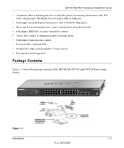
... of sensing the line speed and negotiating the operation duplex mode with the link partner automatically Figure 2-1 illustrates the NETGEAR GS716T Smart Switch front panel: System LEDs Reset PWR ® ProSafe 16 Port Gigabit Smart Switch 1 3 5 7 9 11 13 15 LINK/ACT SPD Green (1000M) Yellow (100M) FDX 2 4 6 8 10 ... The front panel contains the following: • 16 RJ-45 connectors for 10/100/1000 Mbps auto sensing Gigabit Ethernet switching ports. • Two SFP slots for SFP modules supporting 1000 (1000BASE-SX/LX)/100 Mbps SFP. • Reset button to restart the device. • Recessed ...
... of sensing the line speed and negotiating the operation duplex mode with the link partner automatically Figure 2-1 illustrates the NETGEAR GS716T Smart Switch front panel: System LEDs Reset PWR ® ProSafe 16 Port Gigabit Smart Switch 1 3 5 7 9 11 13 15 LINK/ACT SPD Green (1000M) Yellow (100M) FDX 2 4 6 8 10 ... The front panel contains the following: • 16 RJ-45 connectors for 10/100/1000 Mbps auto sensing Gigabit Ethernet switching ports. • Two SFP slots for SFP modules supporting 1000 (1000BASE-SX/LX)/100 Mbps SFP. • Reset button to restart the device. • Recessed ...
GS716Tv2/GS724Tv3 Hardware manual
Page 12
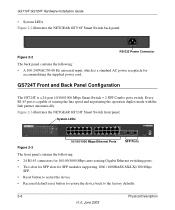
... of sensing the line speed and negotiating the operation duplex mode with the link partner automatically Figure 2-3 illustrates the NETGEAR GS724T Smart Switch front panel: System LEDs Reset PWR ® ProSafe 24 Port Gigabit Smart Switch 1 3 5 7 9 11 13 15 17 19 21 23 LINK/ACT SPD Green (1000M) Yellow (100M)... 10/100/1000 Mbps auto-sensing Gigabit Ethernet switching ports. • Two slots for SFP slots for accommodating the supplied power cord. GS724T Front and Back Panel Configuration The GS724T is a standard AC power receptacle for SFP modules supporting 1000 (1000BASE-SX/LX)/100 Mbps...
... of sensing the line speed and negotiating the operation duplex mode with the link partner automatically Figure 2-3 illustrates the NETGEAR GS724T Smart Switch front panel: System LEDs Reset PWR ® ProSafe 24 Port Gigabit Smart Switch 1 3 5 7 9 11 13 15 17 19 21 23 LINK/ACT SPD Green (1000M) Yellow (100M)... 10/100/1000 Mbps auto-sensing Gigabit Ethernet switching ports. • Two slots for SFP slots for accommodating the supplied power cord. GS724T Front and Back Panel Configuration The GS724T is a standard AC power receptacle for SFP modules supporting 1000 (1000BASE-SX/LX)/100 Mbps...
GS716Tv2/GS724Tv3 Hardware manual
Page 14
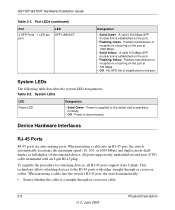
...on the port at 1000 Mbps. • Solid Yellow - Packets transmission or reception is occurring on the port. All ports support only unshielded twisted-pair (UTP) cable terminated with either straight-through or crossover cable. 2-8 Physical Description v1.0, June 2009 Power ...on the port. • Flashing Green - Power is a straight-through or crossover cables. When inserting a cable into the switch's RJ-45 port, the switch automatically: • Senses whether the cable is disconnected. System LEDs LED Power LED Designation • Solid Green - This technology...
...on the port at 1000 Mbps. • Solid Yellow - Packets transmission or reception is occurring on the port. All ports support only unshielded twisted-pair (UTP) cable terminated with either straight-through or crossover cable. 2-8 Physical Description v1.0, June 2009 Power ...on the port. • Flashing Green - Power is a straight-through or crossover cables. When inserting a cable into the switch's RJ-45 port, the switch automatically: • Senses whether the cable is disconnected. System LEDs LED Power LED Designation • Solid Green - This technology...
GS716Tv2/GS724Tv3 Hardware manual
Page 24
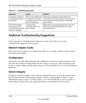
..., restore the original connections and determine the problem by resetting the switch. Additional Troubleshooting Suggestions If the suggestions in the required ports. In North America, call 1-888-NETGEAR. GS716T/GS724T Hardware Installation Guide Table A-1. Troubleshooting Chart Symptom Cause ... all connectors are in this section. Switch Integrity If required, verify the integrity of North America, please refer to the troubleshooting suggestions in working condition and the software driver has been installed. If the problem continues, contact NETGEAR technical support.
..., restore the original connections and determine the problem by resetting the switch. Additional Troubleshooting Suggestions If the suggestions in the required ports. In North America, call 1-888-NETGEAR. GS716T/GS724T Hardware Installation Guide Table A-1. Troubleshooting Chart Symptom Cause ... all connectors are in this section. Switch Integrity If required, verify the integrity of North America, please refer to the troubleshooting suggestions in working condition and the software driver has been installed. If the problem continues, contact NETGEAR technical support.
GS716Tv2/GS724Tv3 Hardware manual
Page 25
Troubleshooting v1.0, June 2009 A-21 GS716T/GS724T Hardware Installation Guide Auto-Negotiation The RJ-45 ports negotiate the correct duplex mode and speed if the device at the other end of the link supports auto negotiation. If the device does not support auto negotiation, the switch only determines the speed correctly and the duplex mode defaults to half-duplex. The gigabit port on the Gigabit module negotiates speed, duplex mode, and flow control, provided that the attached device supports auto-negotiation.
Troubleshooting v1.0, June 2009 A-21 GS716T/GS724T Hardware Installation Guide Auto-Negotiation The RJ-45 ports negotiate the correct duplex mode and speed if the device at the other end of the link supports auto negotiation. If the device does not support auto negotiation, the switch only determines the speed correctly and the duplex mode defaults to half-duplex. The gigabit port on the Gigabit module negotiates speed, duplex mode, and flow control, provided that the attached device supports auto-negotiation.

GS716Tv2/GS724Tv3 Hardware manual
Page 30
...802.3z 1-2 IEEE Standards 1-2 IEEE-compliant 1-2 Installation Guide 1-4 Installing an SFP GBIC Module 4-16 Installing the Switch 4-14 L LED Designations 2-7 LINK/ACT LED 2-7 Low Latency 1-2 M MAC 1-3 Media Access Control 1-3 Mounting Holes 4-14 N Nylon Washers 4-14...Module 2-9 SFP LINK/ACT LED 2-8 SFP Module Bay 4-17 Site Requirements 4-13 Small Form-factor Pluggable (SFP) 1-2 Smart Switch Resource CD 1-4 Smart Wizard Discovery 1-2 Straight-through 2-8 Support Information Card 1-4 System LEDs 2-8 T Temperature 4-14 Traffic Control 1-1 Troubleshooting Chart A-19 U User Intervention 2-9 User's Manual...
...802.3z 1-2 IEEE Standards 1-2 IEEE-compliant 1-2 Installation Guide 1-4 Installing an SFP GBIC Module 4-16 Installing the Switch 4-14 L LED Designations 2-7 LINK/ACT LED 2-7 Low Latency 1-2 M MAC 1-3 Media Access Control 1-3 Mounting Holes 4-14 N Nylon Washers 4-14...Module 2-9 SFP LINK/ACT LED 2-8 SFP Module Bay 4-17 Site Requirements 4-13 Small Form-factor Pluggable (SFP) 1-2 Smart Switch Resource CD 1-4 Smart Wizard Discovery 1-2 Straight-through 2-8 Support Information Card 1-4 System LEDs 2-8 T Temperature 4-14 Traffic Control 1-1 Troubleshooting Chart A-19 U User Intervention 2-9 User's Manual...
GS716Tv2/GS724Tv3 Installation Guide
Page 1
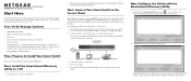
...Software Administration User's Manual is on the Resource CD.) • Warranty/Support Information Card. Double-click the Smartwizard Discovery icon on the Switch front panel. )NSTALLATION'UIDE NETGEAR GS716T/GS724T Smart Switch™ Start Here Follow these connections. Connect each PC to an RJ-...view this screen. 2. If you are using static IP addressing in Windows Start menu Programs to your smart switch. First, Verify Package Contents • NETGEAR Smart Switch • Rubber footpads for tabletop installation • Power cord • Rack-mount kit for its MAC ...
...Software Administration User's Manual is on the Resource CD.) • Warranty/Support Information Card. Double-click the Smartwizard Discovery icon on the Switch front panel. )NSTALLATION'UIDE NETGEAR GS716T/GS724T Smart Switch™ Start Here Follow these connections. Connect each PC to an RJ-...view this screen. 2. If you are using static IP addressing in Windows Start menu Programs to your smart switch. First, Verify Package Contents • NETGEAR Smart Switch • Rubber footpads for tabletop installation • Power cord • Rack-mount kit for its MAC ...
GS716Tv2/GS724Tv3 Installation Guide
Page 2
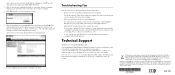
...Support information, see the Resource CD that the IP address configuration of their respective holders. Information is on computer connected to configure. 4. Configure the switch for correcting simple problems you want to the switch with your product at http://www.NETGEAR.com/register. Consult the Reference Manual on your switch. Registration via DHCP. NETGEAR and the NETGEAR...the PC is required before you for product updates and Web support. Troubleshooting Tips Here are some tips for your switch. This symbol was placed in accordance with configuration procedures. ...
...Support information, see the Resource CD that the IP address configuration of their respective holders. Information is on computer connected to configure. 4. Configure the switch for correcting simple problems you want to the switch with your product at http://www.NETGEAR.com/register. Consult the Reference Manual on your switch. Registration via DHCP. NETGEAR and the NETGEAR...the PC is required before you for product updates and Web support. Troubleshooting Tips Here are some tips for your switch. This symbol was placed in accordance with configuration procedures. ...
GS716Tv2/GS724Tv3 Software Admin Manual
Page 2
.../1991 und Vfg 46/1992 aufgeführten Bestimmungen entstört ist. Support Information Phone: 1-888-NETGEAR, for Interference (VCCI) Statement This equipment is hereby certified that the Gigabit Smart Switch has been suppressed in accordance with your Support information card. NETGEAR does not assume any liability that shipped with the regulations may occur due...
.../1991 und Vfg 46/1992 aufgeführten Bestimmungen entstört ist. Support Information Phone: 1-888-NETGEAR, for Interference (VCCI) Statement This equipment is hereby certified that the Gigabit Smart Switch has been suppressed in accordance with your Support information card. NETGEAR does not assume any liability that shipped with the regulations may occur due...
GS716Tv2/GS724Tv3 Software Admin Manual
Page 11
...Chapter 3, "Configuring Switching Information" on page 3-1 describes how to manage and monitor the layer 2 switching features. • Chapter 4, "Configuring Quality of Service" on page 4-1 describes how to manage the GS716T/GS724T...Support providers To obtain the greatest benefit from the basic up to configure the Differentiated Services and Class of the switch's features. However, a greater level of Ethernet and networking concepts. About This Manual The NETGEAR® GS716Tv2 and GS724Tv3 Software Administration Manual describes how to configure and operate the Gigabit Smart Switch...
...Chapter 3, "Configuring Switching Information" on page 3-1 describes how to manage and monitor the layer 2 switching features. • Chapter 4, "Configuring Quality of Service" on page 4-1 describes how to manage the GS716T/GS724T...Support providers To obtain the greatest benefit from the basic up to configure the Differentiated Services and Class of the switch's features. However, a greater level of Ethernet and networking concepts. About This Manual The NETGEAR® GS716Tv2 and GS724Tv3 Software Administration Manual describes how to configure and operate the Gigabit Smart Switch...

GS716Tv2/GS724Tv3 Software Admin Manual
Page 15
Tip: If your browser window. Revision History Part Number Version Number Date 202-10484-01 1.0 July 2009 Description Product Created xv v1.0, July 2009 GS716Tv2 and GS724Tv3 Software Administration Manual • Click the print icon in the upper left of your printer supports printing two pages on a single sheet of paper, you can save paper and printer ink by selecting this feature.
Tip: If your browser window. Revision History Part Number Version Number Date 202-10484-01 1.0 July 2009 Description Product Created xv v1.0, July 2009 GS716Tv2 and GS724Tv3 Software Administration Manual • Click the print icon in the upper left of your printer supports printing two pages on a single sheet of paper, you can save paper and printer ink by selecting this feature.
GS716Tv2/GS724Tv3 Software Admin Manual
Page 31
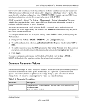
... and private MIBs that displays after a successful login, displays the information you need to configure an SNMP manager to access the switch. Table 1-3 describes common parameter values and value formatting. To enable authentication, select an Authentication Protocol option,...a "-" prefix. The System Management System Information Web page, which is the page that support additional switch functionality. Navigate to accept the spaces. Click Apply. GS716Tv2 and GS724Tv3 Software Administration Manual GS716T/GS724T switches use spaces as part of eight or...
... and private MIBs that displays after a successful login, displays the information you need to configure an SNMP manager to access the switch. Table 1-3 describes common parameter values and value formatting. To enable authentication, select an Authentication Protocol option,...a "-" prefix. The System Management System Information Web page, which is the page that support additional switch functionality. Navigate to accept the spaces. Click Apply. GS716Tv2 and GS724Tv3 Software Administration Manual GS716T/GS724T switches use spaces as part of eight or...
GS716Tv2/GS724Tv3 Software Admin Manual
Page 32
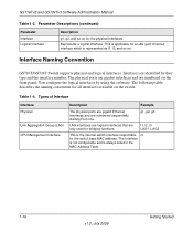
... Convention GS716T/GS724T Switch supports physical and logical interfaces. Types of Interface Interface Physical Link Aggregation Group (LAG) CPU Management Interface Description Example The physical ports are gigabit Ethernet interfaces and are numbered on . l1, l2, l3 LAG1, LAG2 This is represented as l1, l2, and so on the front panel. GS716Tv2 and GS724Tv3 Software...
... Convention GS716T/GS724T Switch supports physical and logical interfaces. Types of Interface Interface Physical Link Aggregation Group (LAG) CPU Management Interface Description Example The physical ports are gigabit Ethernet interfaces and are numbered on . l1, l2, l3 LAG1, LAG2 This is represented as l1, l2, and so on the front panel. GS716Tv2 and GS724Tv3 Software...
GS716Tv2/GS724Tv3 Software Admin Manual
Page 37
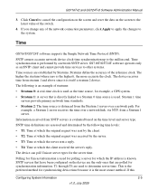
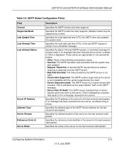
...connection parameters, click Apply to apply the changes to the millisecond. Time GS716T/GS724T software supports the Simple Network Time Protocol (SNTP). Time synchronization is used to determine server time. ... is the preferred method for Unicast information is performed by Stratums. Stratums define the accuracy of the switch. 4. The following time levels: • T1: Time at which the original request was sent ...software operates only as the time source, for the server time. GS716Tv2 and GS724Tv3 Software Administration Manual 3. The higher the stratum (where zero is evaluated based...
...connection parameters, click Apply to apply the changes to the millisecond. Time GS716T/GS724T software supports the Simple Network Time Protocol (SNTP). Time synchronization is used to determine server time. ... is the preferred method for Unicast information is performed by Stratums. Stratums define the accuracy of the switch. 4. The following time levels: • T1: Time at which the original request was sent ...software operates only as the time source, for the server time. GS716Tv2 and GS724Tv3 Software Administration Manual 3. The higher the stratum (where zero is evaluated based...
GS716Tv2/GS724Tv3 Software Admin Manual
Page 41
...• Bad Date Encoded: The time provided by the SNTP server is not valid. • Version Not Supported: The SNTP version supported by the server is displayed. GS716Tv2 and GS724Tv3 Software Administration Manual Table 2-4. Specifies the local date and time (UTC) the SNTP client last updated ...the system clock. If no further queries were to be supported by the client. • Server Unsynchronized: The SNTP server is shown...
...• Bad Date Encoded: The time provided by the SNTP server is not valid. • Version Not Supported: The SNTP version supported by the server is displayed. GS716Tv2 and GS724Tv3 Software Administration Manual Table 2-4. Specifies the local date and time (UTC) the SNTP client last updated ...the system clock. If no further queries were to be supported by the client. • Server Unsynchronized: The SNTP server is shown...
GS716Tv2/GS724Tv3 Software Admin Manual
Page 44
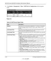
...UTC) that the response from a server. 2-12 v1.0, July 2009 Configuring System Information This is not synchronized with the version supported by a stratum field equal to this SNTP server was last queried. If no Server configuration exists, a message saying "No ...System Management Time SNTP Server Configuration in a message received from this server. Figure 2-6 Table 2-6. SNTP Server Status Fields Field Address Last Update Time Last Attempt Time Last Attempt Status Description Specifies all the existing Server Addresses. GS716Tv2 and GS724Tv3 ...
...UTC) that the response from a server. 2-12 v1.0, July 2009 Configuring System Information This is not synchronized with the version supported by a stratum field equal to this SNTP server was last queried. If no Server configuration exists, a message saying "No ...System Management Time SNTP Server Configuration in a message received from this server. Figure 2-6 Table 2-6. SNTP Server Status Fields Field Address Last Update Time Last Attempt Time Last Attempt Status Description Specifies all the existing Server Addresses. GS716Tv2 and GS724Tv3 ...

