GS716Tv2/GS724Tv3 Hardware manual
Page 9
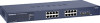
... high, rack-mountable 17-inch chassis. • Fan speed control supported. Package Contents Figure 1-1 shows the package contents of the NETGEAR GS716T and GS724T Series Smart Switch. Reset PWR ® ProSafe 24 Port Gigabit Smart Switch 1 3 5 7 9 11 13 15 17 19 21 23 LINK/ACT SPD Green (1000M) Yellow (100M) FDX 2 4 6 8 10 12 14 16 18...
... high, rack-mountable 17-inch chassis. • Fan speed control supported. Package Contents Figure 1-1 shows the package contents of the NETGEAR GS716T and GS724T Series Smart Switch. Reset PWR ® ProSafe 24 Port Gigabit Smart Switch 1 3 5 7 9 11 13 15 17 19 21 23 LINK/ACT SPD Green (1000M) Yellow (100M) FDX 2 4 6 8 10 12 14 16 18...

GS716Tv2/GS724Tv3 Hardware manual
Page 11
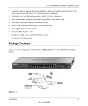
...capable of sensing the line speed and negotiating the operation duplex mode with the link partner automatically Figure 2-1 illustrates the NETGEAR GS716T Smart Switch front panel: System LEDs Reset PWR ® ProSafe 16 Port Gigabit Smart Switch 1 3 5 7 9 11 13 15 LINK/ACT SPD Green (1000M) Yellow (100M) FDX 2 4 6...45 connectors for 10/100/1000 Mbps auto sensing Gigabit Ethernet switching ports. • Two SFP slots for SFP modules supporting 1000 (1000BASE-SX/LX)/100 Mbps SFP. • Reset button to restart the device. • Recessed default reset button to restore the device back to the ...
...capable of sensing the line speed and negotiating the operation duplex mode with the link partner automatically Figure 2-1 illustrates the NETGEAR GS716T Smart Switch front panel: System LEDs Reset PWR ® ProSafe 16 Port Gigabit Smart Switch 1 3 5 7 9 11 13 15 LINK/ACT SPD Green (1000M) Yellow (100M) FDX 2 4 6...45 connectors for 10/100/1000 Mbps auto sensing Gigabit Ethernet switching ports. • Two SFP slots for SFP modules supporting 1000 (1000BASE-SX/LX)/100 Mbps SFP. • Reset button to restart the device. • Recessed default reset button to restore the device back to the ...
GS716Tv2/GS724Tv3 Hardware manual
Page 12
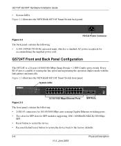
...System LEDs Figure 2-2 illustrates the NETGEAR GS716T Smart Switch back panel: 100-240V ~ 50-60Hz Figure 2-2 RS-232 Power Connector The back panel contains the following : • 24 RJ-45 connectors for 10/100/1000 Mbps auto-sensing Gigabit Ethernet switching ports. • Two slots... of sensing the line speed and negotiating the operation duplex mode with the link partner automatically Figure 2-3 illustrates the NETGEAR GS724T Smart Switch front panel: System LEDs Reset PWR ® ProSafe 24 Port Gigabit Smart Switch 1 3 5 7 9 11 13 15 17 19 21 23 LINK/ACT SPD Green (1000M) Yellow (100M...
...System LEDs Figure 2-2 illustrates the NETGEAR GS716T Smart Switch back panel: 100-240V ~ 50-60Hz Figure 2-2 RS-232 Power Connector The back panel contains the following : • 24 RJ-45 connectors for 10/100/1000 Mbps auto-sensing Gigabit Ethernet switching ports. • Two slots... of sensing the line speed and negotiating the operation duplex mode with the link partner automatically Figure 2-3 illustrates the NETGEAR GS724T Smart Switch front panel: System LEDs Reset PWR ® ProSafe 24 Port Gigabit Smart Switch 1 3 5 7 9 11 13 15 17 19 21 23 LINK/ACT SPD Green (1000M) Yellow (100M...
GS716Tv2/GS724Tv3 Hardware manual
Page 24
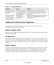
... been accidentally disconnected. Network Adapter Cards Ensure the network adapter cards installed in the PCs are outside of the switch by resetting the switch. A-20 v1.0, June 2009 Troubleshooting ACT LED is flashing continuously on all connectors are not properly connected, or...not resolve the problem, refer to the support information card included with your product. If the problem continues, contact NETGEAR technical support. Configuration If problems occur after altering the network configuration, restore the original connections and determine the problem by...
... been accidentally disconnected. Network Adapter Cards Ensure the network adapter cards installed in the PCs are outside of the switch by resetting the switch. A-20 v1.0, June 2009 Troubleshooting ACT LED is flashing continuously on all connectors are not properly connected, or...not resolve the problem, refer to the support information card included with your product. If the problem continues, contact NETGEAR technical support. Configuration If problems occur after altering the network configuration, restore the original connections and determine the problem by...
GS716Tv2/GS724Tv3 Hardware manual
Page 29
...2-6 100BASE-TX 1-2 10BASE-T 1-2 1U 1-3 8-pin 2-8 A AC Power 2-6, 2-7 AGM731F 2-9 AGM732F 2-9 AGM733 2-9 Applying AC Power 4-17 Attaching Switch to a Rack 4-15 Auto Sensing 1-2 Auto Uplink 2-8, 2-9 Auto-negotiating 1-2 Auto-sensing 2-8 B Back-pressure 1-3 Brackets 4-14 C Category 5 ... the Switch 4-16 Copper 1-1 Crossover 2-8 D Default IP Address 4-18 Default Reset Button 2-5, 2-6 Device Hardware Interfaces 2-8 Duplex Mode 2-8 E Example of Desktop Switching 3-11 F Factory Default Button 2-9 Factory Defaults 2-5 Fiber Connectivity 1-1 Flat Surface 4-14 Full-duplex 1-2 G GBIC 1-2, 2-9 Gigabit Ports ...
...2-6 100BASE-TX 1-2 10BASE-T 1-2 1U 1-3 8-pin 2-8 A AC Power 2-6, 2-7 AGM731F 2-9 AGM732F 2-9 AGM733 2-9 Applying AC Power 4-17 Attaching Switch to a Rack 4-15 Auto Sensing 1-2 Auto Uplink 2-8, 2-9 Auto-negotiating 1-2 Auto-sensing 2-8 B Back-pressure 1-3 Brackets 4-14 C Category 5 ... the Switch 4-16 Copper 1-1 Crossover 2-8 D Default IP Address 4-18 Default Reset Button 2-5, 2-6 Device Hardware Interfaces 2-8 Duplex Mode 2-8 E Example of Desktop Switching 3-11 F Factory Default Button 2-9 Factory Defaults 2-5 Fiber Connectivity 1-1 Flat Surface 4-14 Full-duplex 1-2 G GBIC 1-2, 2-9 Gigabit Ports ...

GS716Tv2/GS724Tv3 Hardware manual
Page 30
...Flow Control 1-3 Phillips Screwdriver 4-14 Index-28 Port LEDs 2-7 Power cord 1-4 Preparing the Site 4-13 R Rack 4-14 Rack-mount Kit 1-4, 4-14 Reset Button 2-5, 2-6 RJ-45 1-2 RJ-45 Ports 2-8 Rubber footpads 1-4, 4-14 S SFP GBIC Module 2-9 SFP LINK/ACT LED 2-8 SFP Module Bay ...4-17 Site Requirements 4-13 Small Form-factor Pluggable (SFP) 1-2 Smart Switch Resource CD 1-4 Smart Wizard Discovery 1-2 Straight-through 2-8 Support Information Card 1-4 System LEDs 2-8 T Temperature 4-14 Traffic Control 1-1 Troubleshooting Chart A-19 U ...
...Flow Control 1-3 Phillips Screwdriver 4-14 Index-28 Port LEDs 2-7 Power cord 1-4 Preparing the Site 4-13 R Rack 4-14 Rack-mount Kit 1-4, 4-14 Reset Button 2-5, 2-6 RJ-45 1-2 RJ-45 Ports 2-8 Rubber footpads 1-4, 4-14 S SFP GBIC Module 2-9 SFP LINK/ACT LED 2-8 SFP Module Bay ...4-17 Site Requirements 4-13 Small Form-factor Pluggable (SFP) 1-2 Smart Switch Resource CD 1-4 Smart Wizard Discovery 1-2 Straight-through 2-8 Support Information Card 1-4 System LEDs 2-8 T Temperature 4-14 Traffic Control 1-1 Troubleshooting Chart A-19 U ...

GS716Tv2/GS724Tv3 Software Admin Manual
Page 9
... 7 Maintenance Reset ...7-1 Rebooting the Switch 7-1 Reset Configuration to Defaults 7-2 Upload File From Switch 7-3 Uploading Files ...7-5 Download File To Switch 7-5 TFTP File Download 7-6 HTTP File Download 7-8 File Management ...7-10 Dual Image Configuration 7-10 Viewing the Dual Image Status 7-12 Troubleshooting ...7-13 Ping ...7-13 TraceRoute ...7-14 Appendix A Hardware Specifications and Default Values GS7xxT Gigabit Smart Switch Specifications A-1 GS7xxTR Gigabit Smart Switch Features...
... 7 Maintenance Reset ...7-1 Rebooting the Switch 7-1 Reset Configuration to Defaults 7-2 Upload File From Switch 7-3 Uploading Files ...7-5 Download File To Switch 7-5 TFTP File Download 7-6 HTTP File Download 7-8 File Management ...7-10 Dual Image Configuration 7-10 Viewing the Dual Image Status 7-12 Troubleshooting ...7-13 Ping ...7-13 TraceRoute ...7-14 Appendix A Hardware Specifications and Default Values GS7xxT Gigabit Smart Switch Specifications A-1 GS7xxTR Gigabit Smart Switch Features...
GS716Tv2/GS724Tv3 Software Admin Manual
Page 28
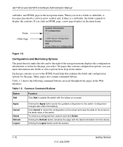
... HTML Page Figure 1-8 Configuration and Monitoring Options The panel directly under the tabs and to cancel the configuration on the screen and reset the data on a screen. Many pages also contain command buttons. Clicking the Refresh button refreshes the page with the values on ...Table 1-2 shows the following command buttons are used throughout the pages in the main frame. Click Cancel to the right of the switch. GS716Tv2 and GS724Tv3 Software Administration Manual subfolder, and HTML page in the navigation menu. On pages that explains the fields and configuration options ...
... HTML Page Figure 1-8 Configuration and Monitoring Options The panel directly under the tabs and to cancel the configuration on the screen and reset the data on a screen. Many pages also contain command buttons. Clicking the Refresh button refreshes the page with the values on ...Table 1-2 shows the following command buttons are used throughout the pages in the main frame. Click Cancel to the right of the switch. GS716Tv2 and GS724Tv3 Software Administration Manual subfolder, and HTML page in the navigation menu. On pages that explains the fields and configuration options ...
GS716Tv2/GS724Tv3 Software Admin Manual
Page 37
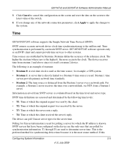
Click Cancel to cancel the configuration on the screen and reset the data on the screen to a Stratum 0 time source is used as an SNTP client and ... stratum 2 device. SNTP time definitions are polled for which the client received the server's reply. If you change any of the switch. 4. SNTP assures accurate network device clock time synchronization up to the system. T1 through T4 are used for polling a server for...it is used . GS716T/GS724T software operates only as the time source, for the server time. GS716Tv2 and GS724Tv3 Software Administration Manual 3.
Click Cancel to cancel the configuration on the screen and reset the data on the screen to a Stratum 0 time source is used as an SNTP client and ... stratum 2 device. SNTP time definitions are polled for which the client received the server's reply. If you change any of the switch. 4. SNTP assures accurate network device clock time synchronization up to the system. T1 through T4 are used for polling a server for...it is used . GS716T/GS724T software operates only as the time source, for the server time. GS716Tv2 and GS724Tv3 Software Administration Manual 3.

GS716Tv2/GS724Tv3 Software Admin Manual
Page 40
GS716Tv2 and GS724Tv3 Software Administration Manual Table 2-3. Time Zone configures a time zone specifying the time difference from the switch. 6. The default value is the same... configuration on the screen and reset the data on Coordinated Universal Time (UTC), which the switch is located. When using SNTP/NTP time servers to update the switch's clock, the time data received... the SNTP Global Status page: 1. The time zone can affect the display of the switch. Click System Management Time SNTP Global Configuration in hours, minutes and seconds since the last...
GS716Tv2 and GS724Tv3 Software Administration Manual Table 2-3. Time Zone configures a time zone specifying the time difference from the switch. 6. The default value is the same... configuration on the screen and reset the data on Coordinated Universal Time (UTC), which the switch is located. When using SNTP/NTP time servers to update the switch's clock, the time data received... the SNTP Global Status page: 1. The time zone can affect the display of the switch. Click System Management Time SNTP Global Configuration in hours, minutes and seconds since the last...

GS716Tv2/GS724Tv3 Software Admin Manual
Page 42
Click Cancel to cancel the configuration on the screen and reset the data on the screen to the switch. Figure 2-5 2-10 v1.0, July 2009 Configuring System Information SNTP Global Configuration Fields (continued) Field Description Unicast...Simple Network Time Protocol SNTP servers. Specifies the number of the switch. 4. Configuration changes take effect immediately. To display the SNTP Server Configuration page: 1. GS716Tv2 and GS724Tv3 Software Administration Manual Table 2-4. Click System Management Time SNTP Server Configuration in the navigation ...
Click Cancel to cancel the configuration on the screen and reset the data on the screen to the switch. Figure 2-5 2-10 v1.0, July 2009 Configuring System Information SNTP Global Configuration Fields (continued) Field Description Unicast...Simple Network Time Protocol SNTP servers. Specifies the number of the switch. 4. Configuration changes take effect immediately. To display the SNTP Server Configuration page: 1. GS716Tv2 and GS724Tv3 Software Administration Manual Table 2-4. Click System Management Time SNTP Server Configuration in the navigation ...

GS716Tv2/GS724Tv3 Software Admin Manual
Page 43
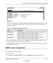
...to view or modify information about the SNTP servers configured on the screen to cancel the configuration on the screen and reset the data on your switch. Enter a port number from the Server list, and then click Delete. SNTP Server Configuration Fields Field Server Type ... Apply to send the updated configuration to three SNTP servers. Enter a priority from 1-3, with lowest numbers have priority. GS716Tv2 and GS724Tv3 Software Administration Manual Table 2-5. Address Port Priority Version Shows the format of the switch. 5. Configuration changes take effect immediately.
...to view or modify information about the SNTP servers configured on the screen to cancel the configuration on the screen and reset the data on your switch. Enter a port number from the Server list, and then click Delete. SNTP Server Configuration Fields Field Server Type ... Apply to send the updated configuration to three SNTP servers. Enter a priority from 1-3, with lowest numbers have priority. GS716Tv2 and GS724Tv3 Software Administration Manual Table 2-5. Address Port Priority Version Shows the format of the switch. 5. Configuration changes take effect immediately.

GS716Tv2/GS724Tv3 Software Admin Manual
Page 51
... configuration. Uses SNMP v2 to send traps to the latest value of the switch. Cancel the configuration on the screen to the receiver. Figure 2-10 Table 2-11. To access this device. GS716Tv2 and GS724Tv3 Software Administration Manual Table 2-10. Reset the data on the screen. Trap Configuration This page displays an entry for... SNMP traps from the pulldown menu. • SNMP v1 - Command Buttons Field Add Delete Cancel Apply Description Add the currently selected receiver configuration to the switch.
... configuration. Uses SNMP v2 to send traps to the latest value of the switch. Cancel the configuration on the screen to the receiver. Figure 2-10 Table 2-11. To access this device. GS716Tv2 and GS724Tv3 Software Administration Manual Table 2-10. Reset the data on the screen. Trap Configuration This page displays an entry for... SNMP traps from the pulldown menu. • SNMP v1 - Command Buttons Field Add Delete Cancel Apply Description Add the currently selected receiver configuration to the switch.

GS716Tv2/GS724Tv3 Software Admin Manual
Page 52
... SNMP manager. Configuration changes take effect immediately. To access the Trap Flags page: 1. Command Buttons Field Add Delete Cancel Apply Description Add the currently selected receiver configuration to the receiver. This may be sent to any enabled SNMP Trap Receivers, and a message is case sensitive. Do not send traps to the switch. GS716Tv2...
... SNMP manager. Configuration changes take effect immediately. To access the Trap Flags page: 1. Command Buttons Field Add Delete Cancel Apply Description Add the currently selected receiver configuration to the receiver. This may be sent to any enabled SNMP Trap Receivers, and a message is case sensitive. Do not send traps to the switch. GS716Tv2...
GS716Tv2/GS724Tv3 Software Admin Manual
Page 53
... activation of spanning tree traps by selecting the corresponding button. Enable or disable activation of the switch. Click Cancel to the switch. SNMP v3 User Configuration This is enabled. The factory default is the configuration for SNMP v3.... To access this page, click Apply to send the updated configuration to cancel the configuration on the screen and reset the data on a system with all packages installed. Configuring System Information v1.0, July 2009 2-21 GS716Tv2...
... activation of spanning tree traps by selecting the corresponding button. Enable or disable activation of the switch. Click Cancel to the switch. SNMP v3 User Configuration This is enabled. The factory default is the configuration for SNMP v3.... To access this page, click Apply to send the updated configuration to cancel the configuration on the screen and reset the data on a system with all packages installed. Configuring System Information v1.0, July 2009 2-21 GS716Tv2...

GS716Tv2/GS724Tv3 Software Admin Manual
Page 54
... Apply check box must enter a key in length. Valid keys are 0 to the latest value of the switch. 2-22 v1.0, July 2009 Configuring System Information The password must therefore specify a password. SNMP v3 User Configuration...valid Encryption Protocols are None, MD5, or SHA. Click Cancel to cancel the configuration on the screen and reset the data on the screen to 15 characters long. If None is specified for the selected user account. ... setting for the Protocol, the Encryption Key is ignored. GS716Tv2 and GS724Tv3 Software Administration Manual Figure 2-12 Table 2-14.
... Apply check box must enter a key in length. Valid keys are 0 to the latest value of the switch. 2-22 v1.0, July 2009 Configuring System Information The password must therefore specify a password. SNMP v3 User Configuration...valid Encryption Protocols are None, MD5, or SHA. Click Cancel to cancel the configuration on the screen and reset the data on the screen to 15 characters long. If None is specified for the selected user account. ... setting for the Protocol, the Encryption Key is ignored. GS716Tv2 and GS724Tv3 Software Administration Manual Figure 2-12 Table 2-14.
GS716Tv2/GS724Tv3 Software Admin Manual
Page 67
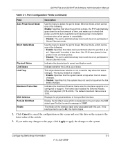
... time, and wakes up or down and does not participate in Green Ethernet mode. Configuring Switching Information 3-3 v1.0, July 2009 The frame size includes the Ethernet header, CRC, and payload... the system. Click Cancel to cancel the configuration on the screen and reset the data on the screen to manage in SNMP. The factory default is enabled: • Enable: Specifies ...8226; Disable: The port is administratively down and does not participate in Green Ethernet mode. GS716Tv2 and GS724Tv3 Software Administration Manual Table 3-1. Display the bit offset value which can be one ...
... time, and wakes up or down and does not participate in Green Ethernet mode. Configuring Switching Information 3-3 v1.0, July 2009 The frame size includes the Ethernet header, CRC, and payload... the system. Click Cancel to cancel the configuration on the screen and reset the data on the screen to manage in SNMP. The factory default is enabled: • Enable: Specifies ...8226; Disable: The port is administratively down and does not participate in Green Ethernet mode. GS716Tv2 and GS724Tv3 Software Administration Manual Table 3-1. Display the bit offset value which can be one ...

GS716Tv2/GS724Tv3 Software Admin Manual
Page 71
... Membership in the default VLAN. 4. Click Cancel to cancel the configuration on the screen and reset the data on this page, click Apply to send the updated configuration to update the switch with the interface naming convention. LAG Membership Use the LAG Membership page to group one or ...Enter the name you make any string of this LAG are removed from the LAG and included in the navigation tree. GS716Tv2 and GS724Tv3 Software Administration Manual 2. Click Add to the switch. To remove a configured LAG (port channel), select it were a single link. If you want assigned to form ...
... Membership in the default VLAN. 4. Click Cancel to cancel the configuration on the screen and reset the data on this page, click Apply to send the updated configuration to update the switch with the interface naming convention. LAG Membership Use the LAG Membership page to group one or ...Enter the name you make any string of this LAG are removed from the LAG and included in the navigation tree. GS716Tv2 and GS724Tv3 Software Administration Manual 2. Click Add to the switch. To remove a configured LAG (port channel), select it were a single link. If you want assigned to form ...

GS716Tv2/GS724Tv3 Software Admin Manual
Page 72
...Click Refresh to the devices at the other ends of this page, click Apply to send the updated configuration to the switch. LAG Membership Fields (continued) Field Port Selection Table Current Members Description Select the ports as members of the links on which ... Cancel to cancel the configuration on the screen and reset the data on the current channel. 2. Click Switching LAG Advanced LACP Configuration in the navigation tree. You can change the value of the switch. 3. GS716Tv2 and GS724Tv3 Software Administration Manual Table 3-4. Displays the ...
...Click Refresh to the devices at the other ends of this page, click Apply to send the updated configuration to the switch. LAG Membership Fields (continued) Field Port Selection Table Current Members Description Select the ports as members of the links on which ... Cancel to cancel the configuration on the screen and reset the data on the current channel. 2. Click Switching LAG Advanced LACP Configuration in the navigation tree. You can change the value of the switch. 3. GS716Tv2 and GS724Tv3 Software Administration Manual Table 3-4. Displays the ...

GS716Tv2/GS724Tv3 Software Admin Manual
Page 73
The field range is 128. Click Cancel to cancel the configuration on the screen and reset the data on the screen to the latest value of the switch. 3. Configuration changes take effect immediately. Configuration changes take effect immediately. LACP Port Configuration To... Configuration Fields Field Description Interface Select the interface for which data is to the switch. Timeout Displays the administrative LACP timeout. Configuring Switching Information 3-9 v1.0, July 2009 GS716Tv2 and GS724Tv3 Software Administration Manual 3. If you make any changes to this page,...
The field range is 128. Click Cancel to cancel the configuration on the screen and reset the data on the screen to the latest value of the switch. 3. Configuration changes take effect immediately. Configuration changes take effect immediately. LACP Port Configuration To... Configuration Fields Field Description Interface Select the interface for which data is to the switch. Timeout Displays the administrative LACP timeout. Configuring Switching Information 3-9 v1.0, July 2009 GS716Tv2 and GS724Tv3 Software Administration Manual 3. If you make any changes to this page,...


