User Manual
Page 3
..., Cable Management ...English-7 Using the Remote ...English-8 Part Names and Functions Control Panel ...English-9 Terminal Panel ...English-10 Remote Control Functions ...English-11 Power, Display, Digital Zoom, Pointer, Main Power Switch Cover ...English-12 Remote Control ID ...English-13 On-Screen Display (OSD) Using the OSD ...English-14 OSD...English-15 Operation Picture Size Using Video Signals ...English-19 Picture Size Using Computer Signals ...English-20 Split Screen Mode ...English-21 Picture in Picture Mode...English-22 Creating a Video Wall ...English-23 Using the Timer...English...
..., Cable Management ...English-7 Using the Remote ...English-8 Part Names and Functions Control Panel ...English-9 Terminal Panel ...English-10 Remote Control Functions ...English-11 Power, Display, Digital Zoom, Pointer, Main Power Switch Cover ...English-12 Remote Control ID ...English-13 On-Screen Display (OSD) Using the OSD ...English-14 OSD...English-15 Operation Picture Size Using Video Signals ...English-19 Picture Size Using Computer Signals ...English-20 Split Screen Mode ...English-21 Picture in Picture Mode...English-22 Creating a Video Wall ...English-23 Using the Timer...English...
User Manual
Page 4
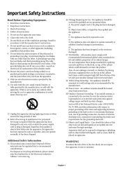
.... Refer all servicing to rain; Servicing is connected to the receiver, be mounted to a wall/ceiling only as to avoid injury from the apparatus. 11. Read these instructions. Do not install near water. Protect the power cord from being walked on apparatus 13. The power supply cord or the plug has been damaged; or E. Heed all instructions. Follow all warnings. Do not use caution when moving...
.... Refer all servicing to rain; Servicing is connected to the receiver, be mounted to a wall/ceiling only as to avoid injury from the apparatus. 11. Read these instructions. Do not install near water. Protect the power cord from being walked on apparatus 13. The power supply cord or the plug has been damaged; or E. Heed all instructions. Follow all warnings. Do not use caution when moving...
User Manual
Page 5
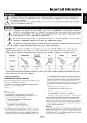
... approved by and complies with radio and television reception. (1) Please use the supplied power cord or equivalent to radio or television reception, which the receiver is connected. • Consult your dealer or an experienced radio/TV technician for additional suggestions. Use the attached specified cables with the P426Y0(P42XP10), P506Y1(P50XP10), or P606Y2(P60XP10) color monitor so as not to interfere with...
... approved by and complies with radio and television reception. (1) Please use the supplied power cord or equivalent to radio or television reception, which the receiver is connected. • Consult your dealer or an experienced radio/TV technician for additional suggestions. Use the attached specified cables with the P426Y0(P42XP10), P506Y1(P50XP10), or P606Y2(P60XP10) color monitor so as not to interfere with...
User Manual
Page 6
... AND USING THE MONITOR: The plasma display's panel is made up of fine picture elements (cells), of detaching the system from the wall outlet and refer servicing to qualified service personnel under the following conditions: • When the power supply cord or plug is strongly recommended not to qualified service personnel. • Do not spill any liquids into the cabinet or use monitor in use for example) light output...
... AND USING THE MONITOR: The plasma display's panel is made up of fine picture elements (cells), of detaching the system from the wall outlet and refer servicing to qualified service personnel under the following conditions: • When the power supply cord or plug is strongly recommended not to qualified service personnel. • Do not spill any liquids into the cabinet or use monitor in use for example) light output...
User Manual
Page 10
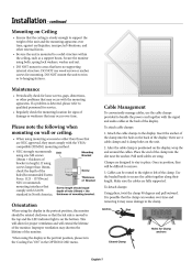
... a solid structure within the ceiling, such as a support beam. If a problem is mounted to the top and the LED indicator light is positioned on the back of the display. There are designed to bundle the power cord together with the mounting apparatus. After the cable clamp is on wall or ceiling. • When using size M8 screws (16mm + thickness of the clamp into the...
... a solid structure within the ceiling, such as a support beam. If a problem is mounted to the top and the LED indicator light is positioned on the back of the display. There are designed to bundle the power cord together with the mounting apparatus. After the cable clamp is on wall or ceiling. • When using size M8 screws (16mm + thickness of the clamp into the...
User Manual
Page 11
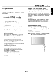
... replaced incorrectly. This can be used batteries. • When replacing, use the Remote Control for the Remote Control Point the top of the sensor. Replace the cover. EXIT INPUT MUTE 30 POWER ON STANDBY RGB PICTURE MODE DVD/HD VIDEO PICTURE MEMORY SIZE 30 1 4 7 2 5 8 0 3 6 9 DISPLAY MENU SET AUTO SET UP + EXIT ZOOM VOL + POINTER + MUTE SPLIT SCREEN PIP S BY S SINGLE SWAP SELECT/FREEZE CAPTURE REMOTE ID SET RESET SLEEP REMOTE CONTROLLER RU-M113 English-8 Press and slide to open the remote control...
... replaced incorrectly. This can be used batteries. • When replacing, use the Remote Control for the Remote Control Point the top of the sensor. Replace the cover. EXIT INPUT MUTE 30 POWER ON STANDBY RGB PICTURE MODE DVD/HD VIDEO PICTURE MEMORY SIZE 30 1 4 7 2 5 8 0 3 6 9 DISPLAY MENU SET AUTO SET UP + EXIT ZOOM VOL + POINTER + MUTE SPLIT SCREEN PIP S BY S SINGLE SWAP SELECT/FREEZE CAPTURE REMOTE ID SET RESET SLEEP REMOTE CONTROLLER RU-M113 English-8 Press and slide to open the remote control...

User Manual
Page 12
... Increases the setting adjustment within OSD menu. 5) MINUS (-) Decreases the setting adjustment within the OSD. 9) Remote control sensor and Power indicator Receives the signal when using the wireless remote control. Mode Power On Standby Power save Diagnosis (Detecting failure) Status indicator light Green Red Amber Red blinking NOTE: The POWER button does not completely turn the main power on /standby. 2) MUTE Switches the audio mute ON/OFF. 3) INPUT Switches between input sources. Glows green when the monitor is off . Part Names and Functions Control Panel 9 EXIT INPUT MUTE...
... Increases the setting adjustment within OSD menu. 5) MINUS (-) Decreases the setting adjustment within the OSD. 9) Remote control sensor and Power indicator Receives the signal when using the wireless remote control. Mode Power On Standby Power save Diagnosis (Detecting failure) Status indicator light Green Red Amber Red blinking NOTE: The POWER button does not completely turn the main power on /standby. 2) MUTE Switches the audio mute ON/OFF. 3) INPUT Switches between input sources. Glows green when the monitor is off . Part Names and Functions Control Panel 9 EXIT INPUT MUTE...
User Manual
Page 13
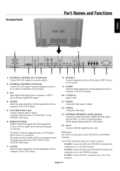
... terminal. SCART3: Connect R/G/B + composite sync. This input can be used with the supplied power cord. to the DVD/HD2 terminals and composite sync. DVD/HD2: Connect equipment such as a DVD player, HDTV device, or set -top box. 9) AUDIO1 Input the audio signal from external equipment such as a computer, VCR or DVD player. 10) S-VIDEO in order to control RS-232C functions. 3) DVI Input digital RGB signals from a computer or HDTV device having a digital RGB output. 4) AUDIO3 Input the audio signal from external equipment such as...
... terminal. SCART3: Connect R/G/B + composite sync. This input can be used with the supplied power cord. to the DVD/HD2 terminals and composite sync. DVD/HD2: Connect equipment such as a DVD player, HDTV device, or set -top box. 9) AUDIO1 Input the audio signal from external equipment such as a computer, VCR or DVD player. 10) S-VIDEO in order to control RS-232C functions. 3) DVI Input digital RGB signals from a computer or HDTV device having a digital RGB output. 4) AUDIO3 Input the audio signal from external equipment such as...
User Manual
Page 14
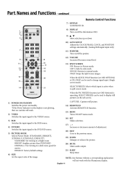
... controls will not work . 2) VIDEO Switches the input signal to the VIDEO source. 3) RGB Switches the input signal to the RGB source. 4) DVD/HD Switches the input signal to normal mode. POWER ON STANDBY 1 2 3 5 RGB DVD/HD VIDEO PICTURE MEMORY 8) DISPLAY Turn on/off the Information OSD. 9) Move selection up or down 10) AUTO SETUP Adjusts the CLOCK PHASE, CLOCK, and POSITION settings automatically. (Analog RGB signal input only) 11) POINTER Turn on/off the pointer. 15 4 6 PICTURE MODE SIZE 1 4 7 7 2 5 8 0 3 6 9 DISPLAY MENU 8 9 AUTO SET UP 12) VOLUME Increases/Decreases sound...
... controls will not work . 2) VIDEO Switches the input signal to the VIDEO source. 3) RGB Switches the input signal to the RGB source. 4) DVD/HD Switches the input signal to normal mode. POWER ON STANDBY 1 2 3 5 RGB DVD/HD VIDEO PICTURE MEMORY 8) DISPLAY Turn on/off the Information OSD. 9) Move selection up or down 10) AUTO SETUP Adjusts the CLOCK PHASE, CLOCK, and POSITION settings automatically. (Analog RGB signal input only) 11) POINTER Turn on/off the pointer. 15 4 6 PICTURE MODE SIZE 1 4 7 7 2 5 8 0 3 6 9 DISPLAY MENU 8 9 AUTO SET UP 12) VOLUME Increases/Decreases sound...

User Manual
Page 16
... SPLIT SCREEN PIP S BY S SINGLE SWAP SELECT/FREEZE CAPTURE REMOTE ID SET RESET SLEEP REMOTE CONTROLLER RU-M113 TO USE REMOTE CONTROL ID MODE ID Mode - The Monitor ID number can then be used in the same area, a remote control in REMOTE CONTROL ID mode will be assigned under the OPTION3 menu in Normal mode or the REMOTE ID is set up to 26 individual monitors. If monitor ID is set to work Remote works POWER ON STANDBY RGB PICTURE MODE DVD/HD VIDEO PICTURE MEMORY SIZE 1 4 7 2 5 8 0 3 6 9 DISPLAY MENU SET AUTO SET UP...
... SPLIT SCREEN PIP S BY S SINGLE SWAP SELECT/FREEZE CAPTURE REMOTE ID SET RESET SLEEP REMOTE CONTROLLER RU-M113 TO USE REMOTE CONTROL ID MODE ID Mode - The Monitor ID number can then be used in the same area, a remote control in REMOTE CONTROL ID mode will be assigned under the OPTION3 menu in Normal mode or the REMOTE ID is set up to 26 individual monitors. If monitor ID is set to work Remote works POWER ON STANDBY RGB PICTURE MODE DVD/HD VIDEO PICTURE MEMORY SIZE 1 4 7 2 5 8 0 3 6 9 DISPLAY MENU SET AUTO SET UP...
User Manual
Page 18
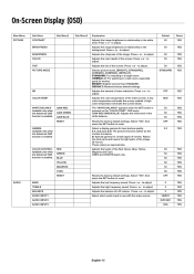
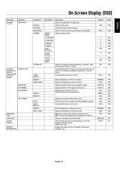
... of the image. RED GREEN BLUE YELLOW MAGENTA CYAN RESET AUDIO BASS TREBLE BALANCE AUDIO INPUT1 AUDIO INPUT2 AUDIO INPUT3 Resets the factory default settings. to adjust. S: Special gamma for best picture quality. 2.1, 2.2, 2.3, 2.4: The picture becomes darker as the number increases. On-Screen Display (OSD) Main Menu PICTURE Sub Menu CONTRAST BRIGHTNESS SHARPNESS COLOR TINT PICTURE MODE Sub Menu2 Sub Menu3 Explanation Adjusts the image brightness in relationship to the background. Adjusts the image brightness in relationship to the white level...
... of the image. RED GREEN BLUE YELLOW MAGENTA CYAN RESET AUDIO BASS TREBLE BALANCE AUDIO INPUT1 AUDIO INPUT2 AUDIO INPUT3 Resets the factory default settings. to adjust. S: Special gamma for best picture quality. 2.1, 2.2, 2.3, 2.4: The picture becomes darker as the number increases. On-Screen Display (OSD) Main Menu PICTURE Sub Menu CONTRAST BRIGHTNESS SHARPNESS COLOR TINT PICTURE MODE Sub Menu2 Sub Menu3 Explanation Adjusts the image brightness in relationship to the background. Adjusts the image brightness in relationship to the white level...
User Manual
Page 19
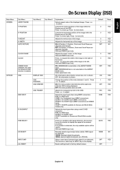
... of the image within the Display area of the image on the display. to narrow the width of the PDP. Adjusts the horizontal size of the image. to move right. is enabled. Change the position of the OSD. RGB: For RGB input. Manually selects signal output when similar 1080I signal are adjusted automatically. Resets settings back to move up. to factory default values. 0 YES Default Reset H-POSITION 0 YES V-HEIGHT H-WIDTH AUTO PICTURE 0 0 OFF...
... of the image within the Display area of the image on the display. to narrow the width of the PDP. Adjusts the horizontal size of the image. to move right. is enabled. Change the position of the OSD. RGB: For RGB input. Manually selects signal output when similar 1080I signal are adjusted automatically. Resets settings back to move up. to factory default values. 0 YES Default Reset H-POSITION 0 YES V-HEIGHT H-WIDTH AUTO PICTURE 0 0 OFF...
User Manual
Page 20
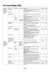
... the monitor waits before going into power save mode after a signal is connected, PLUG/PLAY setting should be "DVI-HD" and the BLACK LEVEL setting should be "HIGH". When it is turned on the input device connected via DVI connector and set to reduce the risk of picture size appears only RGB signals. AUTO: Automatically searches for instructions. Change the loop out setting. Default OFF Reset YES FILM MODE ON YES SCREEN SAVER PLE ORBITER INVERSE WORKING TIME /WAITING TIME Use SCREEN...
... the monitor waits before going into power save mode after a signal is connected, PLUG/PLAY setting should be "DVI-HD" and the BLACK LEVEL setting should be "HIGH". When it is turned on the input device connected via DVI connector and set to reduce the risk of picture size appears only RGB signals. AUTO: Automatically searches for instructions. Change the loop out setting. Default OFF Reset YES FILM MODE ON YES SCREEN SAVER PLE ORBITER INVERSE WORKING TIME /WAITING TIME Use SCREEN...
User Manual
Page 21
... DVI. Sets the mode of the advanced menu items are used. Automatically detects sub screen. Sets the position of each display. OFF VGA AUTO NORMAL 100% OFF ENGLISH AUTO ADVANCED OSM LANGUAGE COLOR SYSTEM SOURCE INFORMATION English-18 English Sets the position of the captured still picture. Display information about the display: frequencies, polarities, etc. OFF YES SPLIT YES 0 0 0 0 OFF 0 0 OFF Adjusts the delay time between being in -picture mode. Default Reset...
... DVI. Sets the mode of the advanced menu items are used. Automatically detects sub screen. Sets the position of each display. OFF VGA AUTO NORMAL 100% OFF ENGLISH AUTO ADVANCED OSM LANGUAGE COLOR SYSTEM SOURCE INFORMATION English-18 English Sets the position of the captured still picture. Display information about the display: frequencies, polarities, etc. OFF YES SPLIT YES 0 0 0 0 OFF 0 0 OFF Adjusts the delay time between being in -picture mode. Default Reset...
User Manual
Page 26
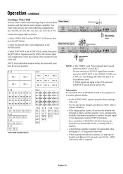
... loop signals out to another plasma display. • Set the VIDEO WALL options properly when creating a video wall. • Use the appropriate (length and efficiency) BNC cable to connect monitors. • If the image quality is set position. 2x2 NO. 1 NO. 2 NO. 10 NO. 4 NO. 3 NO. 13 NO. 11 NO. 14 NO. 12 NO. 15 Video Signal RCA Phono Plug (IN) HD R VD R R IN R L OUT IN EXTERNAL CONTROL DVI L(MONO...
... loop signals out to another plasma display. • Set the VIDEO WALL options properly when creating a video wall. • Use the appropriate (length and efficiency) BNC cable to connect monitors. • If the image quality is set position. 2x2 NO. 1 NO. 2 NO. 10 NO. 4 NO. 3 NO. 13 NO. 11 NO. 14 NO. 12 NO. 15 Video Signal RCA Phono Plug (IN) HD R VD R R IN R L OUT IN EXTERNAL CONTROL DVI L(MONO...
User Manual
Page 31
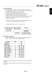
... received an encode. continued 3) Control sequence 1) The command from Plasma monitor Meaning Command for ASCII code) English Sending commands from the PC etc. 30 30 21 0D '0' '0' '!' ' ' Status code from a computer to the Plasma monitor will take 400ms. 2) The Plasma monitor will be ignored. *The sending time of the return command may not operate when changing the signal: Operation POWER ON POWER OFF INPUT VIDEO1 INPUT VIDEO2 INPUT S-VIDEO INPUT DVD...
... received an encode. continued 3) Control sequence 1) The command from Plasma monitor Meaning Command for ASCII code) English Sending commands from the PC etc. 30 30 21 0D '0' '0' '!' ' ' Status code from a computer to the Plasma monitor will take 400ms. 2) The Plasma monitor will be ignored. *The sending time of the return command may not operate when changing the signal: Operation POWER ON POWER OFF INPUT VIDEO1 INPUT VIDEO2 INPUT S-VIDEO INPUT DVD...
User Manual
Page 33
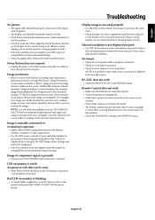
... screen. NOTE: It is changed, the OSD Image Adjust settings may experience a phenomena known as the previous image was on the monitor for as long as Image Persistence. Power Button does not respond • Unplug the power cord of time should be connected. When the display mode is possible to play audio from the video source. English-30 English Image persistence • Please be aware that is not lit (no green or red color...
... screen. NOTE: It is changed, the OSD Image Adjust settings may experience a phenomena known as the previous image was on the monitor for as long as Image Persistence. Power Button does not respond • Unplug the power cord of time should be connected. When the display mode is possible to play audio from the video source. English-30 English Image persistence • Please be aware that is not lit (no green or red color...
User Manual
Page 34
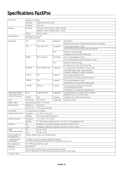
..., Power cord, Users Manual (CD-ROM), Start Up Guide (Paper / CD-ROM), Main Power Switch cover and screw, Cable clamps English-31 Specifications P42XP10 PDP Module Diagonal: 42 "/1058 mm Pixel Pitch Resolution Frequency Horizontal 0.900 mm (W)/0.676 mm (H) 1024 x 768 ANALOG: 15.625/15.734kHz, 31.0kHz - 108.5kHz DIGITAL: 15.625/15.734kHz, 31.0kHz - 91.1kHz Vertical Panel Display Size Input Signals 24Hz...
..., Power cord, Users Manual (CD-ROM), Start Up Guide (Paper / CD-ROM), Main Power Switch cover and screw, Cable clamps English-31 Specifications P42XP10 PDP Module Diagonal: 42 "/1058 mm Pixel Pitch Resolution Frequency Horizontal 0.900 mm (W)/0.676 mm (H) 1024 x 768 ANALOG: 15.625/15.734kHz, 31.0kHz - 108.5kHz DIGITAL: 15.625/15.734kHz, 31.0kHz - 91.1kHz Vertical Panel Display Size Input Signals 24Hz...
User Manual
Page 35
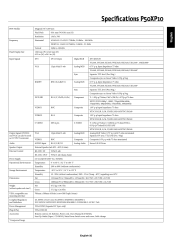
..., Power cord, Users Manual (CD-ROM), Start Up Guide (Paper / CD-ROM), Main Power Switch cover and screw, Cable clamps English-32 English Pixel Pitch 0.81 mm (W)/0.81 mm (H) Specifications P50XP10 PDP Module Diagonal: 50"/1269 mm Resolution Frequency Horizontal 1365 x 768 ANALOG: 15.625/15.734kHz, 31.0kHz - 108.5kHz DIGITAL: 15.625/15.734kHz, 31.0kHz - 91.1kHz Vertical Panel Display Size Input Signals 24Hz...
..., Power cord, Users Manual (CD-ROM), Start Up Guide (Paper / CD-ROM), Main Power Switch cover and screw, Cable clamps English-32 English Pixel Pitch 0.81 mm (W)/0.81 mm (H) Specifications P50XP10 PDP Module Diagonal: 50"/1269 mm Resolution Frequency Horizontal 1365 x 768 ANALOG: 15.625/15.734kHz, 31.0kHz - 108.5kHz DIGITAL: 15.625/15.734kHz, 31.0kHz - 91.1kHz Vertical Panel Display Size Input Signals 24Hz...

User Manual
Page 36
... stand ) VESA compatible arm mounting interface Complied Regulatory and Guidelines Power Management Plug & Play Accessories *Compressed Image Net Gross 700mm x 300mm 4 Holes (screw M8 Depth 16mm) UL 60950-1/CSA C22.2 No.60950-1/EN60950-1/IEC60950-1 FCC-B/DOC-B/EN55022-B/EN55024/EN61000-3-2/EN61000-3-3/CE/C-Tick VESA DPM (Separate HV Sync. only) VESA DDC2B Remote control, AA Batteries, Power cord, Users Manual (CD-ROM), Start Up Guide (Paper / CD-ROM), Main Power Switch cover and screw, Cable...
... stand ) VESA compatible arm mounting interface Complied Regulatory and Guidelines Power Management Plug & Play Accessories *Compressed Image Net Gross 700mm x 300mm 4 Holes (screw M8 Depth 16mm) UL 60950-1/CSA C22.2 No.60950-1/EN60950-1/IEC60950-1 FCC-B/DOC-B/EN55022-B/EN55024/EN61000-3-2/EN61000-3-3/CE/C-Tick VESA DPM (Separate HV Sync. only) VESA DDC2B Remote control, AA Batteries, Power cord, Users Manual (CD-ROM), Start Up Guide (Paper / CD-ROM), Main Power Switch cover and screw, Cable...


