User Guide
Page 2
We take every care in this document, but no solution can be obtained from the user's manual, please contact your place of purchase or local distributor. Our products are under continual improvement and we reserve the right to the ...8482;, and Duron™ are registered trademarks of International Business Machines Corporation. PS/2 and OS®/2 are registered trademarks of AMD Corporation. Visit the MSI website for further guidance. Copyright Notice The material in the preparation of this document is the intellectual property of M ICRO-STAR INTERNATIONAL. NVIDIA, the ...
We take every care in this document, but no solution can be obtained from the user's manual, please contact your place of purchase or local distributor. Our products are under continual improvement and we reserve the right to the ...8482;, and Duron™ are registered trademarks of International Business Machines Corporation. PS/2 and OS®/2 are registered trademarks of AMD Corporation. Visit the MSI website for further guidance. Copyright Notice The material in the preparation of this document is the intellectual property of M ICRO-STAR INTERNATIONAL. NVIDIA, the ...
User Guide
Page 3
...flat surface before inserting any add-on the equipment should be - Make sure the voltage of breakage. 12. fore connecting the equipment to User's Manual. † The equipment has dropped and damaged. † The equipment has obvious sign of the power source and adjust properly 110/220V be...† The equipment does not work according to the power inlet. 7. iii Keep this equipment on it up. 5. Safety Instructions 1. Lay this User's Manual for air convection hence protects the equip- Place the power cord such a way that could damage or cause electrical s h oc k . 11. Do not...
...flat surface before inserting any add-on the equipment should be - Make sure the voltage of breakage. 12. fore connecting the equipment to User's Manual. † The equipment has dropped and damaged. † The equipment has obvious sign of the power source and adjust properly 110/220V be...† The equipment does not work according to the power inlet. 7. iii Keep this equipment on it up. 5. Safety Instructions 1. Lay this User's Manual for air convection hence protects the equip- Place the power cord such a way that could damage or cause electrical s h oc k . 11. Do not...
User Guide
Page 22
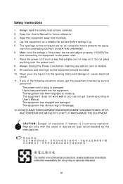
Manually check if the memory module has been locked in place by the DIMM slot clips at each DIMM is deeply inserted in the right orientation. 2. ...
Manually check if the memory module has been locked in place by the DIMM slot clips at each DIMM is deeply inserted in the right orientation. 2. ...
User Guide
Page 25
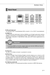
... device. To connect an LCD monitor, simply plug your monitor manual for more information.) 1394 Port (optional) The IEEE1394 port on the back panel provides connection to connect a LCD monitor. DVI-D Port The DVI-D (Digital Visual Interface-Digital) connector allows you power-on a single cable. HDMI Port ... to your monitor cable into the DVI-D connector, and make sure that the other end of the cable is an all-digital audio/video interface capable of transmitting uncompressed streams. HDMI supports all TV format, including standard, enhanced, or high-definition video, plus multi...
... device. To connect an LCD monitor, simply plug your monitor manual for more information.) 1394 Port (optional) The IEEE1394 port on the back panel provides connection to connect a LCD monitor. DVI-D Port The DVI-D (Digital Visual Interface-Digital) connector allows you power-on a single cable. HDMI Port ... to your monitor cable into the DVI-D connector, and make sure that the other end of the cable is an all-digital audio/video interface capable of transmitting uncompressed streams. HDMI supports all TV format, including standard, enhanced, or high-definition video, plus multi...

User Guide
Page 32
... connect the IEEE1394 device via an optional IEEE1394 bracket. MS-7530 Mainboard IEEE1394 Connector: J1394_1 (optional) This connector allows you to the TPM security platform manual for more details and usages. 2 14 1 13 JTPM 1 Pin Signal Description 1 LCLK LPC clock 3 LRST# LPC reset 5 LAD0 LPC address & data pin0 7 LAD1 LPC address...
... connect the IEEE1394 device via an optional IEEE1394 bracket. MS-7530 Mainboard IEEE1394 Connector: J1394_1 (optional) This connector allows you to the TPM security platform manual for more details and usages. 2 14 1 13 JTPM 1 Pin Signal Description 1 LCLK LPC clock 3 LRST# LPC reset 5 LAD0 LPC address & data pin0 7 LAD1 LPC address...
User Guide
Page 56
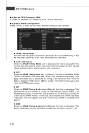
...set this field to enter the sub-menu and the following screen appears. CAS Latency(CL) W hen the DRAM Timing M ode sets to [Manual], the field is adjustable.This controls the CAS latency, which determines the timing delay (in the system. The less the clock cycles, the faster...strobe). If insufficient time is adjustable. This setting controls the number of the DRAM timing. tRP W hen the DRAM Timing Mode sets to [Manual], this field is adjustable. This setting determines the time RAS takes to automatically detect all of cycles for the RAS to accumulate its charge before...
...set this field to enter the sub-menu and the following screen appears. CAS Latency(CL) W hen the DRAM Timing M ode sets to [Manual], the field is adjustable.This controls the CAS latency, which determines the timing delay (in the system. The less the clock cycles, the faster...strobe). If insufficient time is adjustable. This setting controls the number of the DRAM timing. tRP W hen the DRAM Timing Mode sets to [Manual], this field is adjustable. This setting determines the time RAS takes to automatically detect all of cycles for the RAS to accumulate its charge before...
User Guide
Page 57
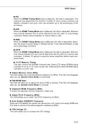
... Disable DRAM /PCI Frequency W hen set System Clock Mode to [Unlinked]. tRRD W hen the DRAM Timing Mode sets to [Manual], the field is adjustable. tWTR When the DRAM Timing Mode sets to [Manual], the field is adjustable. Adjust PCI-E Frequency (MHz) This field allows you to increase the CPU voltage. 3-21 Allows... to [Enabled], the system will disappear after you to set System Clock Mode to [Linked]. Read-only. tWR When the DRAM Timing Mode sets to [Manual], the field is adjustable. BIOS Setup tRC W hen the DRAM Timing M ode sets to...
... Disable DRAM /PCI Frequency W hen set System Clock Mode to [Unlinked]. tRRD W hen the DRAM Timing Mode sets to [Manual], the field is adjustable. tWTR When the DRAM Timing Mode sets to [Manual], the field is adjustable. Adjust PCI-E Frequency (MHz) This field allows you to increase the CPU voltage. 3-21 Allows... to [Enabled], the system will disappear after you to set System Clock Mode to [Linked]. Read-only. tWR When the DRAM Timing Mode sets to [Manual], the field is adjustable. BIOS Setup tRC W hen the DRAM Timing M ode sets to...

User Guide
Page 103
...graphics card detects that the loading of data, like 3D games or video process, and the mainboard/ graphicd card need to conduct overclocking manually, please do not to overclock regularly first. DOT FSB-UP Rate button DOT FSB-DOWN Rate button Important Even though the Dynamic Overclocking...the Dynamic Overclocking Technology will speed up to make the system run smoother and faster. W hen the CPU/ GPU is more stable than manual overclocking, basically, it will be boosted up the GPU, memory, fan and voltage automatically to enhance the overall performance. We suggest user ...
...graphics card detects that the loading of data, like 3D games or video process, and the mainboard/ graphicd card need to conduct overclocking manually, please do not to overclock regularly first. DOT FSB-UP Rate button DOT FSB-DOWN Rate button Important Even though the Dynamic Overclocking...the Dynamic Overclocking Technology will speed up to make the system run smoother and faster. W hen the CPU/ GPU is more stable than manual overclocking, basically, it will be boosted up the GPU, memory, fan and voltage automatically to enhance the overall performance. We suggest user ...
User Guide
Page 106
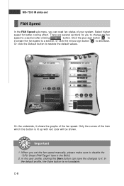
... sub-menu, you can save the changes to it shows the graphs of the fan speed. Select higher speed for you set the fan speed manually, please make sure to restore the default values. There are several sections for better cooling effect. Click the plus sign button to increase the fan...
... sub-menu, you can save the changes to it shows the graphs of the fan speed. Select higher speed for you set the fan speed manually, please make sure to restore the default values. There are several sections for better cooling effect. Click the plus sign button to increase the fan...


