User Guide
Page 2
...your system and no guarantee is given as to make changes without notice. func=service Contact our technical staff at: http://ocss.msi.com.tw ii We take every care in the preparation of this document is the intellectual property of International Business Machines Corporation. ... for FAQ, technical guide, BIOS updates, driver updates, and other countries. Award® is a registered trademark of Intel Corporation. Visit the MSI website for further guidance. W indows® XP/Vista are registered trademarks of American Megatrends Inc. Intel® and Pentium® are registered...
...your system and no guarantee is given as to make changes without notice. func=service Contact our technical staff at: http://ocss.msi.com.tw ii We take every care in the preparation of this document is the intellectual property of International Business Machines Corporation. ... for FAQ, technical guide, BIOS updates, driver updates, and other countries. Award® is a registered trademark of Intel Corporation. Visit the MSI website for further guidance. W indows® XP/Vista are registered trademarks of American Megatrends Inc. Intel® and Pentium® are registered...
User Guide
Page 3
Keep this equipment away from overheating. Do not place anything over the power cord. 8. The openings on card or module. 9. fore connecting the equipment to User's Manual. † The equipment has dropped and damaged. † The equipment has obvious sign of the power source and adjust properly 110/220V be noted. 10. Keep this equipment on if bat ter y i s i nc orrec tl y r epl ac ed. ment from humidity. 4. Make sure the voltage of breakage. 12. Replac e only with the same or equivalent type rec ommended by service personnel: † The power cord or plug is ...
Keep this equipment away from overheating. Do not place anything over the power cord. 8. The openings on card or module. 9. fore connecting the equipment to User's Manual. † The equipment has dropped and damaged. † The equipment has obvious sign of the power source and adjust properly 110/220V be noted. 10. Keep this equipment on if bat ter y i s i nc orrec tl y r epl ac ed. ment from humidity. 4. Make sure the voltage of breakage. 12. Replac e only with the same or equivalent type rec ommended by service personnel: † The power cord or plug is ...
User Guide
Page 4
...radio or television reception, which the receiver is connected. † Consult the dealer or an experienced radio/television technician for a Class B digital device, pursuant to Part 15 of the FCC Rules. iv Notice 2 Shielded interface cables and A.C. This equipment generates, uses and can ...be used in order to comply with the emission limits. Micro-Star International MS-7530 This device complies with Part 15 of the measures listed below. † Reorient or relocate the receiving antenna. ...
...radio or television reception, which the receiver is connected. † Consult the dealer or an experienced radio/television technician for a Class B digital device, pursuant to Part 15 of the FCC Rules. iv Notice 2 Shielded interface cables and A.C. This equipment generates, uses and can ...be used in order to comply with the emission limits. Micro-Star International MS-7530 This device complies with Part 15 of the measures listed below. † Reorient or relocate the receiving antenna. ...
User Guide
Page 5
WEEE (Waste Electrical and Electronic Equipment) Statement v
WEEE (Waste Electrical and Electronic Equipment) Statement v
User Guide
Page 8
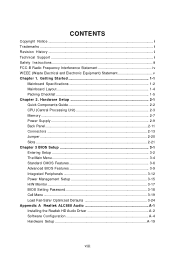
CONTENTS Copyright Notice ...ii Trademarks ...ii Revision History ...ii Technical Support ...ii Safety Instructions ...iii FCC-B Radio Frequency Interference Statement iv W EEE (Waste Electrical and Electronic Equipment) Statement v Chapter 1. Getting Started 1-1 Mainboard Specifications 1-2 Mainboard Layout 1-4 Packing Checklist 1-5 Chapter 2. Hardware Setup 2-1 Quick Components Guide 2-2 CPU (Central Processing Unit 2-3 Memory ...2-7 Power Supply ...2-9 Back Panel ...2-11 Connectors ...2-13 Jumper ...2-20 Slots ...2-21 Chapter 3 BIOS Setup 3-1 Entering Setup ...3-2 The Main Menu ...
CONTENTS Copyright Notice ...ii Trademarks ...ii Revision History ...ii Technical Support ...ii Safety Instructions ...iii FCC-B Radio Frequency Interference Statement iv W EEE (Waste Electrical and Electronic Equipment) Statement v Chapter 1. Getting Started 1-1 Mainboard Specifications 1-2 Mainboard Layout 1-4 Packing Checklist 1-5 Chapter 2. Hardware Setup 2-1 Quick Components Guide 2-2 CPU (Central Processing Unit 2-3 Memory ...2-7 Power Supply ...2-9 Back Panel ...2-11 Connectors ...2-13 Jumper ...2-20 Slots ...2-21 Chapter 3 BIOS Setup 3-1 Entering Setup ...3-2 The Main Menu ...

User Guide
Page 9
Appendix B NVIDIA RAID B-1 Introduction ...B-2 RAID Configuration B-3 Installing Driver ...B-7 NVIDIA RAID Utility Installation B-8 Using the NVMediaShield Software B-11 Appendix C Dual Core Center C-1 Activating Dual Core Center C-2 Main ...C-3 DOT (Dynamic OverClocking C-5 Clock ...C-6 Voltage ...C-7 FAN Speed ...C-8 Temperature ...C-9 User Profile ...C-10 ix
Appendix B NVIDIA RAID B-1 Introduction ...B-2 RAID Configuration B-3 Installing Driver ...B-7 NVIDIA RAID Utility Installation B-8 Using the NVMediaShield Software B-11 Appendix C Dual Core Center C-1 Activating Dual Core Center C-2 Main ...C-3 DOT (Dynamic OverClocking C-5 Clock ...C-6 Voltage ...C-7 FAN Speed ...C-8 Temperature ...C-9 User Profile ...C-10 ix
User Guide
Page 10
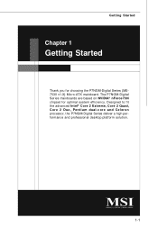
Getting Started Chapter 1 Getting Started Thank you for optimal system efficiency. The P7NGM-Digital Series mainboards are based on NVIDIA® nForce730i chipset for choosing the P7NGM-Digital Series (MS7530 v1.X) Micro-ATX mainboard. Designed to fit the advanced Intel® Core 2 Extreme, Core 2 Quad, Core 2 Duo, Pentium dual-core and Celeron processor, the P7NGM-Digital Series deliver a high performance and professional desktop platform solution. 1-1
Getting Started Chapter 1 Getting Started Thank you for optimal system efficiency. The P7NGM-Digital Series mainboards are based on NVIDIA® nForce730i chipset for choosing the P7NGM-Digital Series (MS7530 v1.X) Micro-ATX mainboard. Designed to fit the advanced Intel® Core 2 Extreme, Core 2 Quad, Core 2 Duo, Pentium dual-core and Celeron processor, the P7NGM-Digital Series deliver a high performance and professional desktop platform solution. 1-1

User Guide
Page 11
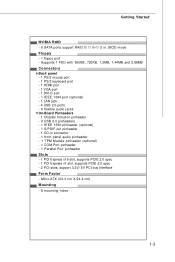
Supports Intel® EIST Technology - m s i. NVIDIA® nForce 730i (MCP7A) Memory Support - DDR2 667/ 800 SDRAM (240pin, 1.8V) - 4 DDR2 DIMMs (16GB Max) (For more information on compatible components, please visit http:/ / g lobal. Supports 10/100/1000 Fast Ethernet by Realtek ALC888 - Chip integrated by Realtek® RTL8111C IEEE 1394 (optional) - p hp ?f un c = c p uf or m 2 ) Supported FSB - 1333/ 1066/ 800 MHz Chipset - fu nc =t es t r ep or t ) LAN - Supports transfer rate up to 400Mbps Audio - Supports Intel® Hyper-Threading (HT) Technology (For the latest ...
Supports Intel® EIST Technology - m s i. NVIDIA® nForce 730i (MCP7A) Memory Support - DDR2 667/ 800 SDRAM (240pin, 1.8V) - 4 DDR2 DIMMs (16GB Max) (For more information on compatible components, please visit http:/ / g lobal. Supports 10/100/1000 Fast Ethernet by Realtek ALC888 - Chip integrated by Realtek® RTL8111C IEEE 1394 (optional) - p hp ?f un c = c p uf or m 2 ) Supported FSB - 1333/ 1066/ 800 MHz Chipset - fu nc =t es t r ep or t ) LAN - Supports transfer rate up to 400Mbps Audio - Supports Intel® Hyper-Threading (HT) Technology (For the latest ...
User Guide
Page 12
Getting Started NVIDIA RAID - 6 SATA ports support RAID 0/ 1/ 0+1/ 5 or JBOD mode Floppy - 1 floppy port - Micro-ATX (24.4 cm X 24.4 cm) Mounting - 8 mounting holes 1-3 Supports 1 FDD with 360KB, 720KB, 1.2MB, 1.44MB and 2.88MB Connectors Back panel - 1 PS/2 mouse port - 1 PS/2 keyboard port - 1 ...
Getting Started NVIDIA RAID - 6 SATA ports support RAID 0/ 1/ 0+1/ 5 or JBOD mode Floppy - 1 floppy port - Micro-ATX (24.4 cm X 24.4 cm) Mounting - 8 mounting holes 1-3 Supports 1 FDD with 360KB, 720KB, 1.2MB, 1.44MB and 2.88MB Connectors Back panel - 1 PS/2 mouse port - 1 PS/2 keyboard port - 1 ...
User Guide
Page 13
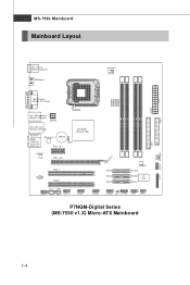
... 88 PCI 1 PCI 2 JCD1 JSP1 JAUD1 J1394_1 (op tional) JUSB1 JUSB2 SATA6 SATA4 SATA2 JMB368 SATA5 SATA3 SATA1 I/O Ch ip JUSB3 JCI1 JTPM1 JFP1 JFP2 P7NGM-Digital Series (MS-7530 v1.X) Micro-ATX Mainboard IDE 1 JLPT1 JCOM1 SYSFAN1 1-4
... 88 PCI 1 PCI 2 JCD1 JSP1 JAUD1 J1394_1 (op tional) JUSB1 JUSB2 SATA6 SATA4 SATA2 JMB368 SATA5 SATA3 SATA1 I/O Ch ip JUSB3 JCI1 JTPM1 JFP1 JFP2 P7NGM-Digital Series (MS-7530 v1.X) Micro-ATX Mainboard IDE 1 JLPT1 JCOM1 SYSFAN1 1-4
User Guide
Page 14
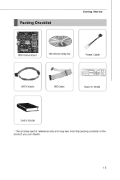
Packing Checklist Getting Started MSI motherboard MSI Driver/Utility CD Power Cable SATA Cable IDE Cable Back IO Shield User's Guide * The pictures are for reference only and may vary from the packing contents of the product you purchased. 1-5
Packing Checklist Getting Started MSI motherboard MSI Driver/Utility CD Power Cable SATA Cable IDE Cable Back IO Shield User's Guide * The pictures are for reference only and may vary from the packing contents of the product you purchased. 1-5

User Guide
Page 15
For some components, if you with the information about hardware setup procedures. While doing the installation, be careful in the wrong orientation, the components will not work properly. Use a grounded wrist strap before handling computer components. Static electricity may damage the components. 2-1 Hardware Setup Chapter 2 Hardware Setup This chapter provides you install in holding the components and follow the installation procedures.
For some components, if you with the information about hardware setup procedures. While doing the installation, be careful in the wrong orientation, the components will not work properly. Use a grounded wrist strap before handling computer components. Static electricity may damage the components. 2-1 Hardware Setup Chapter 2 Hardware Setup This chapter provides you install in holding the components and follow the installation procedures.
User Guide
Page 17
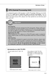
...is the Pin 1 indicator Yellow triangle is designed to support overclocking. Replaceing the CPU While replacing the CPU, always turn off the ATX power supply or unplug the power supply's power cord from overheating. Introduction to operate beyond product specifications. func=cpuform2 Important Overheating Overheating ...of LGA 775 CPU. W hen you are able to enhance heat dissipation. For the latest information about CPU, please visit http://global.msi.com.tw/index.php? We do not have the CPU cooler, consult your components are installing the CPU, make sure the cooling ...
...is the Pin 1 indicator Yellow triangle is designed to support overclocking. Replaceing the CPU While replacing the CPU, always turn off the ATX power supply or unplug the power supply's power cord from overheating. Introduction to operate beyond product specifications. func=cpuform2 Important Overheating Overheating ...of LGA 775 CPU. W hen you are able to enhance heat dissipation. For the latest information about CPU, please visit http://global.msi.com.tw/index.php? We do not have the CPU cooler, consult your components are installing the CPU, make sure the cooling ...
User Guide
Page 18
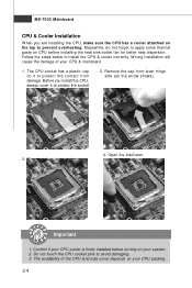
Confirm if your CPU cooler is firmly installed before installing the heat sink/cooler fan for better heat dispersion. The CPU socket has a plastic cap on your system. 2. Remove the cap from damage. Important 1. The availability of the CPU land side cover depends on it to protect the socket pin. 2. The pins of your CPU & mainboard. 1. Meanwhile, do not forget to apply some thermal paste on the top to prevent overheating. W rong installation will cause the damage of socket reveal. 4. Do not touch the CPU socket pins to install the CPU & cooler correctly. MS-7530 ...
Confirm if your CPU cooler is firmly installed before installing the heat sink/cooler fan for better heat dispersion. The CPU socket has a plastic cap on your system. 2. Remove the cap from damage. Important 1. The availability of the CPU land side cover depends on it to protect the socket pin. 2. The pins of your CPU & mainboard. 1. Meanwhile, do not forget to apply some thermal paste on the top to prevent overheating. W rong installation will cause the damage of socket reveal. 4. Do not touch the CPU socket pins to install the CPU & cooler correctly. MS-7530 ...
User Guide
Page 19
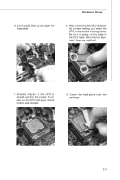
If not, take out the CPU with pure vertical motion and reinstall. 8. Lift the load lever up and open the load plate. 6. Note that the alignment keys are matched. Be sure to grasp on the edge of the CPU base. Hardware Setup 5. Cover the load plate onto the p ac k age. 2-5 Visually inspect if the CPU is seated well into the socket. After confirming the CPU direction for correct mating, put down the CPU in the socket housing frame. alignment key 7.
If not, take out the CPU with pure vertical motion and reinstall. 8. Lift the load lever up and open the load plate. 6. Note that the alignment keys are matched. Be sure to grasp on the edge of the CPU base. Hardware Setup 5. Cover the load plate onto the p ac k age. 2-5 Visually inspect if the CPU is seated well into the socket. After confirming the CPU direction for correct mating, put down the CPU in the socket housing frame. alignment key 7.
User Guide
Page 20
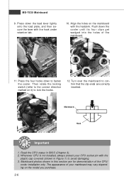
Then rotate the locking switch (refer to the correct direction marked on the mainboard with the heatsink. Turn over the mainboard to lock the hooks. 12. Align the holes on it) to confirm that the clip-ends are for demonstration of the CPU/ cooler installation only. Read the CPU status in this section are correctly inserted. Press down the cooler until its four clips get wedged into the holes of your CPU socket pin with the hook under retention tab. 10. locking switch Mainboard Hook Important 1. The appearance of the mainboard. 11. Push down the load lever lightly ...
Then rotate the locking switch (refer to the correct direction marked on the mainboard with the heatsink. Turn over the mainboard to lock the hooks. 12. Align the holes on it) to confirm that the clip-ends are for demonstration of the CPU/ cooler installation only. Read the CPU status in this section are correctly inserted. Press down the cooler until its four clips get wedged into the holes of your CPU socket pin with the hook under retention tab. 10. locking switch Mainboard Hook Important 1. The appearance of the mainboard. 11. Push down the load lever lightly ...
User Guide
Page 21
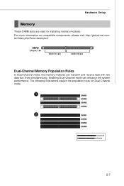
... Memory Population Rules In Dual-Channel mode, the memory modules can enhance the system performance. For more information on compatible components, please visit http://global.msi.com. The following illustrations explain the population rules for installing memory modules. Hardware Setup Memory These DIMM slots are used for Dual-Channel mode. 1 DIMM1...
... Memory Population Rules In Dual-Channel mode, the memory modules can enhance the system performance. For more information on compatible components, please visit http://global.msi.com. The following illustrations explain the population rules for installing memory modules. Hardware Setup Memory These DIMM slots are used for Dual-Channel mode. 1 DIMM1...
User Guide
Page 22
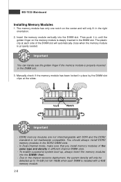
Then push it in until the golden finger on the center and will automatically close when the memory module is properly seated. Manually check if the memory module has been locked in the right orientation. 2. DDR2 memory modules are not interchangeable with DDR and the DDR2 standard is installed with a 4GB memory module. 2-8 You should always install DDR2 memory modules in the DIMM slot. In Dual-Channel mode, make sure that you install memory modules of the DIMM slot will only fit in place by the DIMM slot clips at each DIMM is not backwards compatible. Volt Notch Important ...
Then push it in until the golden finger on the center and will automatically close when the memory module is properly seated. Manually check if the memory module has been locked in the right orientation. 2. DDR2 memory modules are not interchangeable with DDR and the DDR2 standard is installed with a 4GB memory module. 2-8 You should always install DDR2 memory modules in the DIMM slot. In Dual-Channel mode, make sure that you install memory modules of the DIMM slot will only fit in place by the DIMM slot clips at each DIMM is not backwards compatible. Volt Notch Important ...

User Guide
Page 23
... 6 +5V 18 GND 7 GND 19 GND 8 PW R OK 20 Res 9 5VSB 21 +5V 10 +12V 22 +5V 11 +12V 23 +5V 12 +3.3V 24 GND ATX 4-Pin Power Connector: JPWR2 This power connector is also a foolproof design on pin 11, 12, 23 & 24 to the CPU. Make sure that all the... connectors are aligned. JPWR2 4 2 3 1 Pin Definition PIN SIGNAL 1 GND 2 GND 3 12V 4 12V pin 13 pin 12 Important 1. If you like to use the 20-pin ATX power supply as you 'd like . There is used to provide power to avoid wrong installation. Hardware Setup Power Supply...
... 6 +5V 18 GND 7 GND 19 GND 8 PW R OK 20 Res 9 5VSB 21 +5V 10 +12V 22 +5V 11 +12V 23 +5V 12 +3.3V 24 GND ATX 4-Pin Power Connector: JPWR2 This power connector is also a foolproof design on pin 11, 12, 23 & 24 to the CPU. Make sure that all the... connectors are aligned. JPWR2 4 2 3 1 Pin Definition PIN SIGNAL 1 GND 2 GND 3 12V 4 12V pin 13 pin 12 Important 1. If you like to use the 20-pin ATX power supply as you 'd like . There is used to provide power to avoid wrong installation. Hardware Setup Power Supply...
User Guide
Page 24
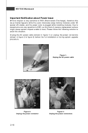
Figure 1: Unplug the AC power cable Figure 2: Unplug the power connector 2-10 Figure 3: Unplug the power connectors Please follow the following solution to avoid this kind of memory-replacement actions might cause system chipset unable to boot. Due to several pins are very sensitive to ESD (Electrostatic Discharge), therefore this issue mostly happens while the users intensively swap memory modules under S5 (power-off) states, and the power code is very sensitive to ESD, so this situation. MS-7530 Mainboard Important Notification about Power Issue NForce chipset is plugged while ...
Figure 1: Unplug the AC power cable Figure 2: Unplug the power connector 2-10 Figure 3: Unplug the power connectors Please follow the following solution to avoid this kind of memory-replacement actions might cause system chipset unable to boot. Due to several pins are very sensitive to ESD (Electrostatic Discharge), therefore this issue mostly happens while the users intensively swap memory modules under S5 (power-off) states, and the power code is very sensitive to ESD, so this situation. MS-7530 Mainboard Important Notification about Power Issue NForce chipset is plugged while ...