User Guide
Page 4
These limits are designed to provide reasonable protection against harmful interference in accordance with the emission limits. Micro-Star International MS-7530 This device complies with the limits for a Class B digital device, pursuant to Part 15 of the FCC Rules. iv If this device must be determined by turning the equipment off and on, the...
These limits are designed to provide reasonable protection against harmful interference in accordance with the emission limits. Micro-Star International MS-7530 This device complies with the limits for a Class B digital device, pursuant to Part 15 of the FCC Rules. iv If this device must be determined by turning the equipment off and on, the...

User Guide
Page 11
... - Supports Intel® EIST Technology - m s i. Transfer rate is up to 3 Gb/s 1-2 Supports transfer rate up to 7.1 Channel audio-out - t w / i ndex. Chip integrated by JMicron JMB381 - m s i. MS-7530 Mainboard Mainboard Specifications Processor Support - core and Celeron in the LGA775 package -
... - Supports Intel® EIST Technology - m s i. Transfer rate is up to 3 Gb/s 1-2 Supports transfer rate up to 7.1 Channel audio-out - t w / i ndex. Chip integrated by JMicron JMB381 - m s i. MS-7530 Mainboard Mainboard Specifications Processor Support - core and Celeron in the LGA775 package -
User Guide
Page 13
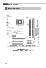
JPWR1 FDD 1 MS-7530 Mainboard Mainboard Layout Top : mouse Bot tom: keybo ard HDMI port CP UFAN1 DIMM1 DIMM2 DIMM3 DIMM4 Top:VGA port Bottom: DVI-D port Top: 139 4(... 88 PCI 1 PCI 2 JCD1 JSP1 JAUD1 J1394_1 (op tional) JUSB1 JUSB2 SATA6 SATA4 SATA2 JMB368 SATA5 SATA3 SATA1 I/O Ch ip JUSB3 JCI1 JTPM1 JFP1 JFP2 P7NGM-Digital Series (MS-7530 v1.X) Micro-ATX Mainboard IDE 1 JLPT1 JCOM1 SYSFAN1 1-4
JPWR1 FDD 1 MS-7530 Mainboard Mainboard Layout Top : mouse Bot tom: keybo ard HDMI port CP UFAN1 DIMM1 DIMM2 DIMM3 DIMM4 Top:VGA port Bottom: DVI-D port Top: 139 4(... 88 PCI 1 PCI 2 JCD1 JSP1 JAUD1 J1394_1 (op tional) JUSB1 JUSB2 SATA6 SATA4 SATA2 JMB368 SATA5 SATA3 SATA1 I/O Ch ip JUSB3 JCI1 JTPM1 JFP1 JFP2 P7NGM-Digital Series (MS-7530 v1.X) Micro-ATX Mainboard IDE 1 JLPT1 JCOM1 SYSFAN1 1-4
User Guide
Page 18
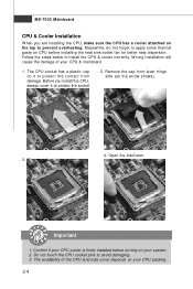
... land side cover depends on your system. 2. The CPU socket has a plastic cap on the top to prevent overheating. The pins of your CPU & mainboard. 1. MS-7530 Mainboard CPU & Cooler Installation W hen you install the CPU, always cover it to protect the contact from lever hinge side (as the arrow shows). 3. Confirm...
... land side cover depends on your system. 2. The CPU socket has a plastic cap on the top to prevent overheating. The pins of your CPU & mainboard. 1. MS-7530 Mainboard CPU & Cooler Installation W hen you install the CPU, always cover it to protect the contact from lever hinge side (as the arrow shows). 3. Confirm...
User Guide
Page 20
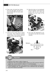
... its four clips get wedged into the holes of the CPU/ cooler installation only. Mainboard photos shown in BIOS (Chapter 3). 2. locking switch Mainboard Hook Important 1. MS-7530 Mainboard 9. Press down the load lever lightly onto the load plate, and then secure the lever with the heatsink.
... its four clips get wedged into the holes of the CPU/ cooler installation only. Mainboard photos shown in BIOS (Chapter 3). 2. locking switch Mainboard Hook Important 1. MS-7530 Mainboard 9. Press down the load lever lightly onto the load plate, and then secure the lever with the heatsink.
User Guide
Page 22
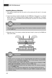
... install DDR2 memory modules in place by the DIMM slot clips at each DIMM is installed with DDR and the DDR2 standard is properly seated. MS-7530 Mainboard Installing Memory Modules 1. The memory module has only one notch on the memory module is properly inserted in the right orientation. 2. Then push it...
... install DDR2 memory modules in place by the DIMM slot clips at each DIMM is installed with DDR and the DDR2 standard is properly seated. MS-7530 Mainboard Installing Memory Modules 1. The memory module has only one notch on the memory module is properly inserted in the right orientation. 2. Then push it...
User Guide
Page 24
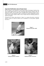
... pins are very sensitive to ESD, so this kind of memory-replacement actions might cause system chipset unable to ESD (Electrostatic Discharge), therefore this situation. MS-7530 Mainboard Important Notification about Power Issue NForce chipset is plugged while installing modules. Please follow the following solution to avoid this issue mostly happens while...
... pins are very sensitive to ESD, so this kind of memory-replacement actions might cause system chipset unable to ESD (Electrostatic Discharge), therefore this situation. MS-7530 Mainboard Important Notification about Power Issue NForce chipset is plugged while installing modules. Please follow the following solution to avoid this issue mostly happens while...
User Guide
Page 26
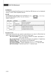
... jack is for microphones. Mic (Pink) - On (brighter & pulsing) The computer is established. Mic, is a connector for connection to Yellow the Local Area Network (LAN). MS-7530 Mainboard USB Port The USB (Universal Serial Bus) port is for attaching USB devices such as keyboard, mouse, or other audio devices. On (steady state...
... jack is for microphones. Mic (Pink) - On (brighter & pulsing) The computer is established. Mic, is a connector for connection to Yellow the Local Area Network (LAN). MS-7530 Mainboard USB Port The USB (Universal Serial Bus) port is for attaching USB devices such as keyboard, mouse, or other audio devices. On (steady state...
User Guide
Page 28
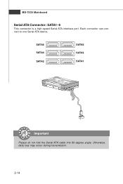
SATA6 SATA4 SATA2 SATA5 SATA3 SATA1 Important Please do not fold the Serial ATA cable into 90-degree angle. MS-7530 Mainboard Serial ATA Connector: SATA1~6 This connector is a high-speed Serial ATA interface port. Each connector can connect to one Serial ATA device. Otherwise, data loss may occur during transmission. 2-14
SATA6 SATA4 SATA2 SATA5 SATA3 SATA1 Important Please do not fold the Serial ATA cable into 90-degree angle. MS-7530 Mainboard Serial ATA Connector: SATA1~6 This connector is a high-speed Serial ATA interface port. Each connector can connect to one Serial ATA device. Otherwise, data loss may occur during transmission. 2-14
User Guide
Page 30
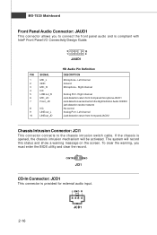
... is provided for external audio input. Left channel Jack detection return from the High Definition Audio CODEC jack detection resistor network No control Analog Port - MS-7530 Mainboard Front Panel Audio Connector: JAUD1 This connector allows you must enter the BIOS utility and clear the record. 1 CINTRU GND JCI1 CD-In Connector...
... is provided for external audio input. Left channel Jack detection return from the High Definition Audio CODEC jack detection resistor network No control Analog Port - MS-7530 Mainboard Front Panel Audio Connector: JAUD1 This connector allows you must enter the BIOS utility and clear the record. 1 CINTRU GND JCI1 CD-In Connector...

User Guide
Page 32
MS-7530 Mainboard IEEE1394 Connector: J1394_1 (optional) This connector allows you to a TPM (Trusted Platform Module) module (optional). Pin Definition 2 10 1 9 J1394_1 PIN SIGNAL PIN 1 TPA+ 2 3 Ground 4 5 ...
MS-7530 Mainboard IEEE1394 Connector: J1394_1 (optional) This connector allows you to a TPM (Trusted Platform Module) module (optional). Pin Definition 2 10 1 9 J1394_1 PIN SIGNAL PIN 1 TPA+ 2 3 Ground 4 5 ...
User Guide
Page 34
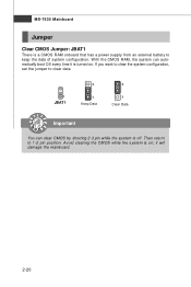
Then return to keep the data of system configuration. If you want to clear the system configuration, set the jumper to clear data. 1 JBAT1 3 1 Keep Data 3 1 Clear Data Important You can automatically boot OS every time it will damage the mainboard. 2-20 W ith the CMOS RAM, the system can clear CMOS by shorting 2-3 pin while the system is turned on ; MS-7530 Mainboard Jumper Clear CMOS Jumper: JBAT1 There is on . it is off. Avoid clearing the CMOS while the system is a CMOS RAM onboard that has a power supply from an external battery to 1-2 pin position.
Then return to keep the data of system configuration. If you want to clear the system configuration, set the jumper to clear data. 1 JBAT1 3 1 Keep Data 3 1 Clear Data Important You can automatically boot OS every time it will damage the mainboard. 2-20 W ith the CMOS RAM, the system can clear CMOS by shorting 2-3 pin while the system is turned on ; MS-7530 Mainboard Jumper Clear CMOS Jumper: JBAT1 There is on . it is off. Avoid clearing the CMOS while the system is a CMOS RAM onboard that has a power supply from an external battery to 1-2 pin position.

User Guide
Page 36
... or higher - 2 x 1 GB of Advanced BIOS Features in Performance mode and that GeForce Boost is enabled. The hybrid icon indicates that supports Hybrid SLI technology. MS-7530 Mainboard Hybrid SLI Technology Hybrid SLI technology, based on the system and install the driver of Hybrid SLI technology. System Request 1. After then, power on...
... or higher - 2 x 1 GB of Advanced BIOS Features in Performance mode and that GeForce Boost is enabled. The hybrid icon indicates that supports Hybrid SLI technology. MS-7530 Mainboard Hybrid SLI Technology Hybrid SLI technology, based on the system and install the driver of Hybrid SLI technology. System Request 1. After then, power on...
User Guide
Page 38
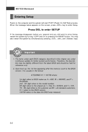
MS-7530 Mainboard Entering Setup Power on the screen, press key to enter Setup, restart the system by simultaneously pressing , , and keys. Important 1. The items under each BIOS category described in the format: A7530NMS V1.1 100708 where: 1st digit refers to BIOS maker as A = AMI, W = AWARD, and P = PHOENIX. 2nd - 5th digit... disappears before you respond and you still wish to enter Setup. V1.1 refers to the BIOS version. 100708 refers to the customer as MS = all standard customers. W hen the message below appears on the computer and the system will start POST (Power On Self Test) ...
MS-7530 Mainboard Entering Setup Power on the screen, press key to enter Setup, restart the system by simultaneously pressing , , and keys. Important 1. The items under each BIOS category described in the format: A7530NMS V1.1 100708 where: 1st digit refers to BIOS maker as A = AMI, W = AWARD, and P = PHOENIX. 2nd - 5th digit... disappears before you respond and you still wish to enter Setup. V1.1 refers to the BIOS version. 100708 refers to the customer as MS = all standard customers. W hen the message below appears on the computer and the system will start POST (Power On Self Test) ...

User Guide
Page 40
... for power management. Load Fail-Safe Defaults Use this menu to set by the BIOS vendor for basic system configurations, such as time, date etc. MS-7530 Mainboard The Main Menu Standard CMOS Features Use this menu for stable system performance. 3-4
... for power management. Load Fail-Safe Defaults Use this menu to set by the BIOS vendor for basic system configurations, such as time, date etc. MS-7530 Mainboard The Main Menu Standard CMOS Features Use this menu for stable system performance. 3-4
User Guide
Page 42
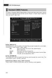
... (usually the current time). day Day of the week, from Sun to set the system to enter the sub-menu, and the following screen appears. 3-6 MS-7530 Mainboard Standard CMOS Features The items in Standard CMOS Features Menu include some basic setup items. Use the arrow keys to highlight the item and...
... (usually the current time). day Day of the week, from Sun to set the system to enter the sub-menu, and the following screen appears. 3-6 MS-7530 Mainboard Standard CMOS Features The items in Standard CMOS Features Menu include some basic setup items. Use the arrow keys to highlight the item and...
User Guide
Page 44
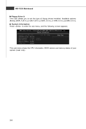
This sub-menu shows the CPU information, BIOS version and memory status of floppy drives installed. System Information Press to set the type of your system (read only). 3-8 Available options: [None], [360K, 5.25 in.], [1.2M, 5.25 in.], [720K, 3.5 in.], [1.44M, 3.5 in.], [2.88M, 3.5 in.]. MS-7530 Mainboard Floppy Drive A This item allows you to enter the sub-menu, and the following screen appears.
This sub-menu shows the CPU information, BIOS version and memory status of floppy drives installed. System Information Press to set the type of your system (read only). 3-8 Available options: [None], [360K, 5.25 in.], [1.2M, 5.25 in.], [720K, 3.5 in.], [1.44M, 3.5 in.], [2.88M, 3.5 in.]. MS-7530 Mainboard Floppy Drive A This item allows you to enter the sub-menu, and the following screen appears.

User Guide
Page 46
... execute and where it via the various ACPI methods. 3-10 Set Limit CPUID MaxVal to 3 The Max CPUID Value Limit is your primary graphics adapter. MS-7530 Mainboard Primary Graphic's Adapter This setting specifies which graphics card is designed to limit the listed speed of the processor to older operating systems. rating...
... execute and where it via the various ACPI methods. 3-10 Set Limit CPUID MaxVal to 3 The Max CPUID Value Limit is your primary graphics adapter. MS-7530 Mainboard Primary Graphic's Adapter This setting specifies which graphics card is designed to limit the listed speed of the processor to older operating systems. rating...

User Guide
Page 48
... to invoke the Boot ROM of the LAN controller. Extra IDE Controller This item allows you to enable/disable the onboard HD audio controller. 3-12 MS-7530 Mainboard Integrated Peripherals USB Controller This setting allows you to use a USB-interfaced device in the operating system. USB Device Legacy Support Select [Enabled] if...
... to invoke the Boot ROM of the LAN controller. Extra IDE Controller This item allows you to enable/disable the onboard HD audio controller. 3-12 MS-7530 Mainboard Integrated Peripherals USB Controller This setting allows you to use a USB-interfaced device in the operating system. USB Device Legacy Support Select [Enabled] if...
User Guide
Page 50
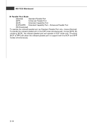
To operate the onboard parallel port in ECP mode only. By choosing [ECP], the onboard parallel port will allow the onboard parallel port to support both the ECP and EPP modes simultaneously. 3-14 MS-7530 Mainboard Parallel Port M ode [Normal] Standard Parallel Port [EPP] Enhanced Parallel Port [ECP] Extended Capability Port [ECP& EPP] Extended Capability Port + Enhanced Parallel Port [Bi-Directional] To operate the onboard parallel port as Standard Parallel Port only, choose [Normal]. Choosing [ECP & EPP] will operate in the EPP mode simultaneously, choose [EPP].
To operate the onboard parallel port in ECP mode only. By choosing [ECP], the onboard parallel port will allow the onboard parallel port to support both the ECP and EPP modes simultaneously. 3-14 MS-7530 Mainboard Parallel Port M ode [Normal] Standard Parallel Port [EPP] Enhanced Parallel Port [ECP] Extended Capability Port [ECP& EPP] Extended Capability Port + Enhanced Parallel Port [Bi-Directional] To operate the onboard parallel port as Standard Parallel Port only, choose [Normal]. Choosing [ECP & EPP] will operate in the EPP mode simultaneously, choose [EPP].


