User Guide
Page 2
... intellectual property of Phoenix Technologies Ltd. func=service Contact our technical staff at: http://ocss.msi.com.tw ii Trademarks All trademarks are registered trademarks of International Business Machines Corporation. W indows® XP/Vista are registered trademarks of AMD Corporation. Revision History Revision V1.1 Revision History Update memory capacity Date October 2008 Technical Support If a problem arises with your...
... intellectual property of Phoenix Technologies Ltd. func=service Contact our technical staff at: http://ocss.msi.com.tw ii Trademarks All trademarks are registered trademarks of International Business Machines Corporation. W indows® XP/Vista are registered trademarks of AMD Corporation. Revision History Revision V1.1 Revision History Update memory capacity Date October 2008 Technical Support If a problem arises with your...
User Guide
Page 8
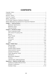
... Components Guide 2-2 CPU (Central Processing Unit 2-3 Memory ...2-7 Power Supply ...2-9 Back Panel ...2-11 Connectors ...2-13 Jumper ...2-20 Slots ...2-21 Chapter 3 BIOS Setup 3-1 Entering Setup ...3-2 The Main Menu ...3-4 Standard CMOS Features 3-6 Advanced BIOS Features 3-9 Integrated Peripherals 3-12 Power Management Setup 3-15 H/W Monitor ...3-17 BIOS Setting Password 3-18 Cell Menu ...3-19 Load Fail-Safe/ Optimized Defaults 3-24 Appendix A Realtek ALC888 Audio A-1 Installing the Realtek HD Audio Driver A-2 Software Configuration A-4 Hardware Setup A-19 viii Getting Started...
... Components Guide 2-2 CPU (Central Processing Unit 2-3 Memory ...2-7 Power Supply ...2-9 Back Panel ...2-11 Connectors ...2-13 Jumper ...2-20 Slots ...2-21 Chapter 3 BIOS Setup 3-1 Entering Setup ...3-2 The Main Menu ...3-4 Standard CMOS Features 3-6 Advanced BIOS Features 3-9 Integrated Peripherals 3-12 Power Management Setup 3-15 H/W Monitor ...3-17 BIOS Setting Password 3-18 Cell Menu ...3-19 Load Fail-Safe/ Optimized Defaults 3-24 Appendix A Realtek ALC888 Audio A-1 Installing the Realtek HD Audio Driver A-2 Software Configuration A-4 Hardware Setup A-19 viii Getting Started...

User Guide
Page 11
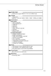
.../s 1-2 Intel® Core 2 Extrem e, Core 2 Quad, Core 2 Duo, Pentium dual- c om . Compliant with Azalia 1.0 Spec IDE - 1 IDE port by Realtek ALC888 - Supports Ultra DMA 66/100 mode and PIO, Bus Master operation m ode SATA - 6 SATAII ports by nForce 730i - Supports Intel® EIST Technology - NVIDIA® nForce 730i (MCP7A) Memory Support - t w / i ndex. fu nc =t es t r ep or t ) LAN - Transfer rate is up to 7.1 Channel audio-out - m s i. c om . Supports Intel® Hyper...
.../s 1-2 Intel® Core 2 Extrem e, Core 2 Quad, Core 2 Duo, Pentium dual- c om . Compliant with Azalia 1.0 Spec IDE - 1 IDE port by Realtek ALC888 - Supports Ultra DMA 66/100 mode and PIO, Bus Master operation m ode SATA - 6 SATAII ports by nForce 730i - Supports Intel® EIST Technology - NVIDIA® nForce 730i (MCP7A) Memory Support - t w / i ndex. fu nc =t es t r ep or t ) LAN - Transfer rate is up to 7.1 Channel audio-out - m s i. c om . Supports Intel® Hyper...
User Guide
Page 12
...- 4 USB 2.0 ports - 6 flexible audio jacks On-Board Pinheaders - 1 Chassis Intrusion pinheader - 3 USB 2.0 pinheaders - 1 IEEE 1394 pinheader (optional) - 1 S/PDIF-out pinheader - 1 CD-in connector - 1 front panel audio pinheader - 1 TPM Module pinheader (optional) - 1 COM Port pinheader - 1 Parallel Port pinheader Slots - 1 PCI Express x16 slot, supports PCIE 2.0 spec - 1 PCI Express x1 slot, supports PCIE 2.0 spec - 2 PCI slots, support 3.3V/ 5V PCI bus Interface Form Factor - Getting Started NVIDIA RAID - 6 SATA ports support RAID 0/ 1/ 0+1/ 5 or JBOD mode Floppy - 1 floppy port - Micro-ATX...
...- 4 USB 2.0 ports - 6 flexible audio jacks On-Board Pinheaders - 1 Chassis Intrusion pinheader - 3 USB 2.0 pinheaders - 1 IEEE 1394 pinheader (optional) - 1 S/PDIF-out pinheader - 1 CD-in connector - 1 front panel audio pinheader - 1 TPM Module pinheader (optional) - 1 COM Port pinheader - 1 Parallel Port pinheader Slots - 1 PCI Express x16 slot, supports PCIE 2.0 spec - 1 PCI Express x1 slot, supports PCIE 2.0 spec - 2 PCI slots, support 3.3V/ 5V PCI bus Interface Form Factor - Getting Started NVIDIA RAID - 6 SATA ports support RAID 0/ 1/ 0+1/ 5 or JBOD mode Floppy - 1 floppy port - Micro-ATX...

User Guide
Page 23
... power connector is highly recommended for system stability. 2-9 Hardware Setup Power Supply ATX 24-Pin Power Connector: JPWR1 This connector allows you like. JPWR2 4 2 3 1 Pin Definition PIN SIGNAL 1 GND 2 GND 3 12V 4 12V pin 13 pin 12 Important 1. If you'd like to use the 20-pin ATX power supply as you to the image at the right hand). To connect the ATX 24-pin power supply, make sure the plug of the mainboard. 2. You may use the 20-pin ATX power supply, please plug...
... power connector is highly recommended for system stability. 2-9 Hardware Setup Power Supply ATX 24-Pin Power Connector: JPWR1 This connector allows you like. JPWR2 4 2 3 1 Pin Definition PIN SIGNAL 1 GND 2 GND 3 12V 4 12V pin 13 pin 12 Important 1. If you'd like to use the 20-pin ATX power supply as you to the image at the right hand). To connect the ATX 24-pin power supply, make sure the plug of the mainboard. 2. You may use the 20-pin ATX power supply, please plug...
User Guide
Page 25
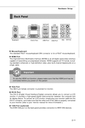
... high-definition video, plus multi-channel digital audio on the system. VGA Port The DB15-pin female connector is for a PS/2® mouse/keyboard. To connect an LCD monitor, simply plug your monitor manual for monitor. It provides a high-speed digital interconnection between the computer and its display device. DVI-D Port The DVI-D (Digital Visual Interface-Digital) connector allows you power-on a single cable. Hardware Setup Back Panel Mouse HDMI Port Keyboard VGA Port DVI-D Port (optional) 1394 Port LAN Line-In RS-Out Line-Out CS-Out USB Port USB Port...
... high-definition video, plus multi-channel digital audio on the system. VGA Port The DB15-pin female connector is for a PS/2® mouse/keyboard. To connect an LCD monitor, simply plug your monitor manual for monitor. It provides a high-speed digital interconnection between the computer and its display device. DVI-D Port The DVI-D (Digital Visual Interface-Digital) connector allows you power-on a single cable. Hardware Setup Back Panel Mouse HDMI Port Keyboard VGA Port DVI-D Port (optional) 1394 Port LAN Line-In RS-Out Line-Out CS-Out USB Port USB Port...
User Guide
Page 27
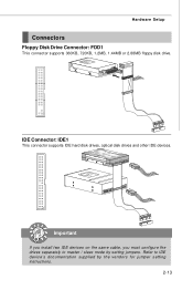
Hardware Setup Connectors Floppy Disk Drive Connector: FDD1 This connector supports 360KB, 720KB, 1.2MB, 1.44MB or 2.88MB floppy disk drive. Refer to master / slave mode by the vendors for jumper setting instructions. 2-13 IDE Connector: IDE1 This connector supports IDE hard disk drives, optical disk drives and other IDE devices. Important If you install two IDE devices on the same cable, you must configure the drives separately to IDE device's documentation supplied by setting jumpers.
Hardware Setup Connectors Floppy Disk Drive Connector: FDD1 This connector supports 360KB, 720KB, 1.2MB, 1.44MB or 2.88MB floppy disk drive. Refer to master / slave mode by the vendors for jumper setting instructions. 2-13 IDE Connector: IDE1 This connector supports IDE hard disk drives, optical disk drives and other IDE devices. Important If you install two IDE devices on the same cable, you must configure the drives separately to IDE device's documentation supplied by setting jumpers.
User Guide
Page 34
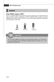
it is off. Avoid clearing the CMOS while the system is a CMOS RAM onboard that has a power supply from an external battery to keep the data of system configuration. If you want to clear the system configuration, set the jumper to 1-2 pin position. MS-7530 Mainboard Jumper Clear CMOS Jumper: JBAT1 There is on . Then return to clear data. 1 JBAT1 3 1 Keep Data 3 1 Clear Data Important You can automatically boot OS every time it will damage the mainboard. 2-20 W ith the CMOS RAM, the system can clear CMOS by shorting 2-3 pin while the system is turned on ;
it is off. Avoid clearing the CMOS while the system is a CMOS RAM onboard that has a power supply from an external battery to keep the data of system configuration. If you want to clear the system configuration, set the jumper to 1-2 pin position. MS-7530 Mainboard Jumper Clear CMOS Jumper: JBAT1 There is on . Then return to clear data. 1 JBAT1 3 1 Keep Data 3 1 Clear Data Important You can automatically boot OS every time it will damage the mainboard. 2-20 W ith the CMOS RAM, the system can clear CMOS by shorting 2-3 pin while the system is turned on ;

User Guide
Page 35
... power supply first. The PCI IRQ pins are typically connected to configure any necessary hardware or software settings for the expansion card, such as follows: PCI Slot 1 PCI Slot 2 Order 1 INT Y# INT Z# Order 2 INT Z# INT W# Order 3 INT W# INT X# Order 4 INT X# INT Y# 2-21 Hardware Setup Slots PCI-E (Peripheral Component Interconnect-Express) Slot The PCI Express slots are compliant with PCI specifications. 32-bit PCI Slot Important When adding or removing expansion cards, make sure that comply with PCIE 2.0 spec and support the PCI Express...
... power supply first. The PCI IRQ pins are typically connected to configure any necessary hardware or software settings for the expansion card, such as follows: PCI Slot 1 PCI Slot 2 Order 1 INT Y# INT Z# Order 2 INT Z# INT W# Order 3 INT W# INT X# Order 4 INT X# INT Y# 2-21 Hardware Setup Slots PCI-E (Peripheral Component Interconnect-Express) Slot The PCI Express slots are compliant with PCI specifications. 32-bit PCI Slot Important When adding or removing expansion cards, make sure that comply with PCIE 2.0 spec and support the PCI Express...
User Guide
Page 43
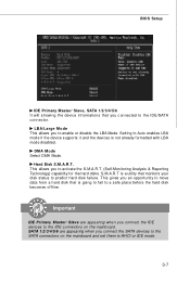
Setting to Auto enables LBA mode if the device supports it and the devices is a utility that monitors your disk status to predict hard disk failure. This allows you connected to the IDE/SATA connector. Hard Disk S.M.A.R.T. SATA 1/2/3/4/5/6 are appearing when you connect the SATA devices to the SATA connectors on the mainboard. Important IDE Primary Master/ Slave are appearing when you connect the IDE devices to the IDE connectors on the mainboard and set them to AHCI or IDE mode. 3-7 BIOS Setup IDE Primary Master/ Slave, SATA 1/2/3/4/5/6 It will showing the...
Setting to Auto enables LBA mode if the device supports it and the devices is a utility that monitors your disk status to predict hard disk failure. This allows you connected to the IDE/SATA connector. Hard Disk S.M.A.R.T. SATA 1/2/3/4/5/6 are appearing when you connect the SATA devices to the SATA connectors on the mainboard. Important IDE Primary Master/ Slave are appearing when you connect the IDE devices to the IDE connectors on the mainboard and set them to AHCI or IDE mode. 3-7 BIOS Setup IDE Primary Master/ Slave, SATA 1/2/3/4/5/6 It will showing the...

User Guide
Page 45
... mode will turn on the Num Lock key when the system is powered on the numeric keypad. To find out which MPS (Multi-Processor Specification) version to be used to enable or disable the APIC (Advanced Programmable Interrupt Controller). Settings are: [Enabled] Shows a still image (logo) on the bootup screen. IOAPIC Function This field is able to run in APIC mode. Advanced BIOS Features BIOS Setup Full Screen LOGO Display...
... mode will turn on the Num Lock key when the system is powered on the numeric keypad. To find out which MPS (Multi-Processor Specification) version to be used to enable or disable the APIC (Advanced Programmable Interrupt Controller). Settings are: [Enabled] Shows a still image (logo) on the bootup screen. IOAPIC Function This field is able to run in APIC mode. Advanced BIOS Features BIOS Setup Full Screen LOGO Display...

User Guide
Page 46
... Max CPUID Value Limit is designed to limit the listed speed of the processor to older operating systems. rating systems. Chipset Feature Press to enter the sub-menu and the following screen appears: HPET The HPET (High Precision Event Timers) is a component that is your primary graphics adapter. CPU Feature Press to enter the sub-menu and the following screen appears: Execute Bit Support Intel's Execute Disable Bit...
... Max CPUID Value Limit is designed to limit the listed speed of the processor to older operating systems. rating systems. Chipset Feature Press to enter the sub-menu and the following screen appears: HPET The HPET (High Precision Event Timers) is a component that is your primary graphics adapter. CPU Feature Press to enter the sub-menu and the following screen appears: Execute Bit Support Intel's Execute Disable Bit...
User Guide
Page 47
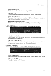
... boot device. On-Chip VGA This setting allows you to set the first/ second boot device where BIOS attempts to load the disk operating system. This setting controls the exact memory size shared to the onboard VGA card. if the system fails to boot from other device. Boot Sequence Press to enter the sub-menu and the following screen appears: TCG/TPM SUPPORT Setting the option to [Yes] enables TPM (Trusted Platform Module) to the system. VGA Share Memory The...
... boot device. On-Chip VGA This setting allows you to set the first/ second boot device where BIOS attempts to load the disk operating system. This setting controls the exact memory size shared to the onboard VGA card. if the system fails to boot from other device. Boot Sequence Press to enter the sub-menu and the following screen appears: TCG/TPM SUPPORT Setting the option to [Yes] enables TPM (Trusted Platform Module) to the system. VGA Share Memory The...

User Guide
Page 49
... IDE drives. It has the following options: [Disabled] [3BC/IRQ7] Line Printer port 0 [278/IRQ5] Line Printer port 2 [378/IRQ7] Line Printer port 1 3-13 Setting options: [RAID],[AHCI] or [IDE]. RAID mode This item allows you to enable/ disable BIOS to use PCI busmastering for reading/ writing to enter the sub-menu and the following screen appears: COM Port 1 Select an address and corresponding interrupt for the first serial port. On-Chip SATA Controller This item allows users to configure SATA mode. I /O chipset...
... IDE drives. It has the following options: [Disabled] [3BC/IRQ7] Line Printer port 0 [278/IRQ5] Line Printer port 2 [378/IRQ7] Line Printer port 1 3-13 Setting options: [RAID],[AHCI] or [IDE]. RAID mode This item allows you to enable/ disable BIOS to use PCI busmastering for reading/ writing to enter the sub-menu and the following screen appears: COM Port 1 Select an address and corresponding interrupt for the first serial port. On-Chip SATA Controller This item allows users to configure SATA mode. I /O chipset...
User Guide
Page 52
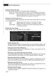
.... Setting to RAM) sleep state. Resume By PCI Device (PM E#) W hen set to [Enabled], the feature allows your system will be awakened from S3 power saving modes when input signal of the PS/2 keyboard/ Mouse is turned off state. [On] Always leaves the computer in the power on state. [Last State] Restores the system to enable or disable the feature of the power button. MS-7530 Mainboard Power Button...
.... Setting to RAM) sleep state. Resume By PCI Device (PM E#) W hen set to [Enabled], the feature allows your system will be awakened from S3 power saving modes when input signal of the PS/2 keyboard/ Mouse is turned off state. [On] Always leaves the computer in the power on state. [Last State] Restores the system to enable or disable the feature of the power button. MS-7530 Mainboard Power Button...
User Guide
Page 53
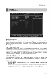
... set the field to select percentage of the monitored hardware devices/ components such as CPU voltage, temperatures and all fans' speeds. 3-17 CPU M in "CPU Smart FAN Target", this item will appear. PC Health Status CPU/ System Temperature, CPU FAN/ SYS FAN1 Speed, CPU Vcore, 3. 3V, 5V, 12V These items display the current status of all of minimum speed limit for cooling down automatically . FAN Speed (%) W hen you to [Reset]. H/W Monitor BIOS Setup Chassis Intrusion The field enables...
... set the field to select percentage of the monitored hardware devices/ components such as CPU voltage, temperatures and all fans' speeds. 3-17 CPU M in "CPU Smart FAN Target", this item will appear. PC Health Status CPU/ System Temperature, CPU FAN/ SYS FAN1 Speed, CPU Vcore, 3. 3V, 5V, 12V These items display the current status of all of minimum speed limit for cooling down automatically . FAN Speed (%) W hen you to [Reset]. H/W Monitor BIOS Setup Chassis Intrusion The field enables...
User Guide
Page 55
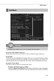
... SpeedStep technology allows you installed the CPU which support speedstep technology. This item allows you are familiar with the chipset. This field will appear after you to [Linked] or [Unlinked], the field is adjustable. System Clock Mode This item is running on battery or AC power. Current CPU/ DRAM Frequency These items show the current clocks of the microprocessor whether the computer is used to switch...
... SpeedStep technology allows you installed the CPU which support speedstep technology. This item allows you are familiar with the chipset. This field will appear after you to [Linked] or [Unlinked], the field is adjustable. System Clock Mode This item is running on battery or AC power. Current CPU/ DRAM Frequency These items show the current clocks of the microprocessor whether the computer is used to switch...
User Guide
Page 85
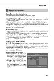
... configuration and exit. Entering the RAID BIOS Setup 1. Define a New Array window will reboot right away. Enter the W indows OS, run the W indows nForce Setup application and install the RAID software. (Check B-8 for configuring NVRAID: Non-Bootable RAID Array 1. Initialize the NVRAID Array Disks. The PC will appear. Choose the hard disks that has the RAID driver to make part of the system POST and boot process prior to Optimal. Bootable RAID...
... configuration and exit. Entering the RAID BIOS Setup 1. Define a New Array window will reboot right away. Enter the W indows OS, run the W indows nForce Setup application and install the RAID software. (Check B-8 for configuring NVRAID: Non-Bootable RAID Array 1. Initialize the NVRAID Array Disks. The PC will appear. Choose the hard disks that has the RAID driver to make part of the system POST and boot process prior to Optimal. Bootable RAID...
User Guide
Page 89
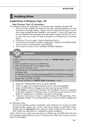
...-ROM drive. 2. Notice: Each time you may encounter a message stating, "Setup could not determine the type of the drivers while installing W indows XP. 1. W hen you start installing Windows XP and older operating systems, you add a new hard drive to a RAID array, the RAID driver will not have to be prompted to a medium (floppy disk/ CD/ DVD or USB). 4. If this is completed, then take out the floppy. 9. Press the "S" key...
...-ROM drive. 2. Notice: Each time you may encounter a message stating, "Setup could not determine the type of the drivers while installing W indows XP. 1. W hen you start installing Windows XP and older operating systems, you add a new hard drive to a RAID array, the RAID driver will not have to be prompted to a medium (floppy disk/ CD/ DVD or USB). 4. If this is completed, then take out the floppy. 9. Press the "S" key...
User Guide
Page 101
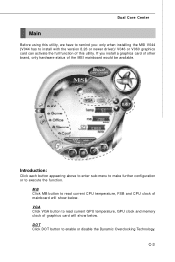
... further configuration or to enable or disable the Dynamic Overclocking Technology. C-3 If you : only when installing the MSI V044 (V044 has to install with the version 8.26 or newer driver)/ V046 or V060 graphics card can activate the full function of this utility. VGA Click VGA button to read current CPU temperature, FSB and CPU clock of mainboard will show below . DOT Click DOT button to execute the function. Dual Core Center Main Before using this utility...
... further configuration or to enable or disable the Dynamic Overclocking Technology. C-3 If you : only when installing the MSI V044 (V044 has to install with the version 8.26 or newer driver)/ V046 or V060 graphics card can activate the full function of this utility. VGA Click VGA button to read current CPU temperature, FSB and CPU clock of mainboard will show below . DOT Click DOT button to execute the function. Dual Core Center Main Before using this utility...

