MSI MS-7512-010 Support Question
MSI MS-7512-010 Support Question
Find answers below for this question about MSI MS-7512-010 - P45 Zilent Motherboard.Need a MSI MS-7512-010 manual? We have 1 online manual for this item!
Question posted by Anonymous-140800 on July 28th, 2014
Incomplete Manual
you manual is incomplete missin pages in section 2, does not stop at 2-26
Current Answers
Answer #1: Posted by BusterDoogen on July 28th, 2014 5:16 PM
BusterDoogen

Member since:
October 30th, 2011 Points: 28,565,427

Member since:
October 30th, 2011 Points: 28,565,427
Go here to download the full manual.
I hope this is helpful to you!
Please respond to my effort to provide you with the best possible solution by using the "Acceptable Solution" and/or the "Helpful" buttons when the answer has proven to be helpful. Please feel free to submit further info for your question, if a solution was not provided. I appreciate the opportunity to serve you!
Related MSI MS-7512-010 Manual Pages
User Guide - Page 4

... experienced radio/television technician for compliance could void the user's authority to the following two conditions: (1) this device may cause undesired operation. Micro-Star International MS-7512
This device complies with the limits for a Class B digital device, pursuant to Part 15 of the FCC Rules. FCC-B Radio Frequency Interference Statement
T h is eq...
User Guide - Page 11

... DMA 66/100/133 mode - Supports 1394 by Realtek® ALC888/ALC888T - MS-7512 Mainboard
Mainboard Specifications
Processor Support - Chip integrated by Jmicron 381
1-2 Flexible 8-channel audio...- Meet Microsoft Vista Premium spec - c om .
m si. North Bridge: Intel® P45 chipset - Supports storage and data transfers at up MHz * (For the latest information about CPU...
User Guide - Page 13

MS-7512 Mainboard
Mainboard Layout
To p : mouse Bo ttom: ke yboard
POWER1
Top: USB po rts Bottom: 1394 port...orts
T:L ine-In M:Line-Out B:Mic T:RS-Out M:CS-Out B:SS-Out
RTL8111C
SYSFAN2
SYSFAN1 JPWR1
PCI_E1
PCI_E2 JB2 JB1
PCI_E3
PCI_E4
Intel P45
JSPI1
JCI1 JBAT1
Intel ICH10R
SATA7 SATA8
IDE 1 SATA5-6 SATA2-4 SATA1-3
ALC888
PCI1
PCI2 JAUD1 JCD1
B AT T
+
RESET
JSPDO1 J1394_1 JFP2...
User Guide - Page 18

... pins of the CPU land side cover depends on your CPU & mainboard.
1. Do not touch the CPU socket pins to install the CPU & cooler correctly. MS-7512 Mainboard
CPU & Cooler Installation
W hen you install the CPU, always cover it to prevent overheating. Remove the cap from damage. Open the load lever. Meanwhile...
User Guide - Page 20
...
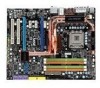
plastic cap covered (shown in Figure 1) to the correct direction marked on the model you purchase.
2-6 Read the CPU status in this section are correctly inserted. The appearance of the CPU/
cooler installation only. MS-7512 Mainboard
9. Push down to lock the h ook s .
12. Align the holes on the mainboard with the heatsink.
User Guide - Page 22

... center and will automatically close when the memory module is properly inserted in the right orientation.
2. Manually check if the memory module has been locked in the DIMM slot. Volt
Notch
Important
- In Dual... channel DIMM slots.
- The plastic clip at the sides. MS-7512 Mainboard
Installing Memory Modules
1. Insert the memory module vertically into the DIM M1 first.
2-8
User Guide - Page 24

You can connect a network cable to external speakers through an optical fiber cable.
Off
10 Mbit/sec data rate is for connection to IEEE1394 devices. MS-7512 Mainboard
Back Panel
Mouse
USB Ports
LAN
L-In RS-Out
Keyboard
eSATA Port
L-Out CS-Out
Optical
1394
S/PDIF
Port
Out
(Optional)
Clear CMOS Button
...
User Guide - Page 26
MS-7512 Mainboard
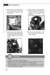
Connectors
Floppy Disk Drive Connector: FDD1
This connector supports 360KB, 720KB, 1.2MB, 1.44MB or 2.88MB floppy disk drive. IDE1
Important
If you install two ...
User Guide - Page 28
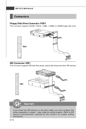
... +12V; If the mainboard has a System Hardware Monitor chipset on the screen. Chassis Intrusion Connector: JCI1
This connector connects to the chassis intrusion switch cable. MS-7512 Mainboard
Fan Power Connectors: CPUFAN1, SYSFAN1~5
The fan power connectors support system cooling fan with speed sensor to take advantage of the CPU fan control.
User Guide - Page 30

Please refer to a TPM (Trusted Platform Module) module (optional). MS-7512 Mainboard
JSPI Debugging Pin Header: JSPI1
The pin header is for more details and usages.
2
14
1
13
Pin Signal
...9
Reserved
PIN SIGNAL
2
VCC3_SB
4
SPI_MOSI_F
6
SPI_CLK_F
8
GND
10 NC
TPM Module Connector: JTPM1
This connector connects to the TPM security platform manual for internal debugging only.
User Guide - Page 32

... Power Switch high reference pull-up Reset Switch high reference pull-up Power Switch low reference pull-down to the front panel switches and LEDs. MS-7512 Mainboard
Front Panel Connectors: JFP1, JFP2
These connectors are for electrical connection to GND Reserved. Speaker
-
+
+-
User Guide - Page 34

Follow the instructions below to set to set the computer's function. MS-7512 Mainboard
Jumper
The motherboard provides the following jumper for you power off the system before changing the jumpers 2. This section will explain how to increase the processor frequency by changing the jumpers JB1 and JB2. Overclocking may cause system instability or crash...
User Guide - Page 36
... section will explain how to reset the system.
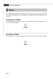
Press the button to change your motherboard's function through the use of button. Power Button: POWER
This power button is used to turnon or turn -off the system. Press the button to turn-on or turn -off the system. RESET
2-22
MS-7512 Mainboard
Button
The motherboard...
User Guide - Page 38

... settings for the expansion card, such as follows:
PCI Slot 1 PCI Slot 2
Order 1 INT A# INT B#
Order 2 INT B# INT C#
Order 3 INT C# INT D#
Order 4 INT D# INT A#
2-24 MS-7512 Mainboard
PCI (Peripheral Component Interconnect) Slot
The PCI slot supports LAN card, SCSI card, USB card, and other add-on cards that comply with PCI...
User Guide - Page 40

MS-7512 Mainboard
3.W hen all of the hardware and software has been properly set up and installed, reboot the system. ...The following aspect appears in the Catalyst™ Control Center that needs to be enabled for more details, please consult the graphics card manual from the view drop menu. for CrossFire™ to operate. After entering the O.S., click the "Catalyst™ Control Center" ...
User Guide - Page 42

MS-7512 Mainboard
Name Status LED16 Lights when system is functional. LED2 Lights when PCI_E2 slot is on . LED6 Lights when PCI1 slot is in 1 phase power ...
User Guide - Page 45
...Important
1.
You may be slightly different from the latest BIOS and should be held for better system performance. MS-7512 Mainboard
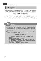
Entering Setup
Power on the screen, press key to enter Setup, restart the system by simultaneously pressing ,...PHOENIX. 2nd - 5th digit refers to the model number. 6th digit refers to the chipset as MS = all standard customers. It is the BIOS version.
User Guide - Page 63

... RAS takes to read from and write to a memory cell.
3-20 MS-7512 Mainboard
Advance DRAM Configuration Press to retain data. The less the clock cycles, the faster the DRAM performance.
tRFC W hen the Configuration DRAM Timing by SPD sets to [Manual], this setting determines the time RFC takes to read command after...
User Guide - Page 65
MS-7512 Mainboard
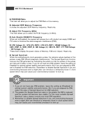
FSB/DRAM Ratio This item will allow you to adjust the FSB/Ratio of Memory, FSB and...But if you do not have any EMI problem, leave the setting at [Disabled] for EMI reduction.
2. Spread Spectrum W hen the motherboard's clock generator pulses, the extreme values (spikes) of the pulses create EMI (Electromagnetic Interference). If you are reduced to select the PCIE...
User Guide - Page 98

...the plus sign button
to
increase the fan speed to a section, or click the minus sign button
to restore the default values.
B-8
Only the curves of the fan speed. MS-7512 Mainboard
FAN Speed
In the FAN Speed sub-menu, you can..." item in the BIOS.
2. Select higher
speed for you set the fan speed manually, please make sure to a section after clicking
button. On the underside, it .
Similar Questions

Where Can I Purchase The P45 Diamond Motherboard Ms-7516 V1.0 Drivers Cd?
(Posted by blackbootheng6836 9 years ago)

Need Network Driver For My Msi Motherboard Ms#7597 Ver. 2.0
(Posted by Anonymous-140116 9 years ago)

How To Reset Bios On Msi Motherboard Ms-7309 Ver:2.1
(Posted by fieclip 10 years ago)

Forgot The Combination Of Wires Of The Power Socket
I got the combinations for wires which were fixed into the power socket of msi motherboard ms 7528...
I got the combinations for wires which were fixed into the power socket of msi motherboard ms 7528...
(Posted by ianatheight 11 years ago)
Sdram And Msi Motherboard
my mother board MS7512 P45 neo2does not recognize sdram DDR2 PC 6400 on channel A and B
my mother board MS7512 P45 neo2does not recognize sdram DDR2 PC 6400 on channel A and B
(Posted by messaoudriadh 11 years ago)