User Manual
Page 2
...Revision V1.0 Revision History First release for FAQ, technical guide, BIOS updates, driver updates, and other information: http://www.msi.com/index.php?func=service ◙ Contact our technical staff at: http://ocss.msi.com ii Trademarks All trademarks are under continual improvement and we ...please contact your place of purchase or local distributor. Alternatively, please try the following help resources for further guidance. ◙ Visit the MSI website for PCB 1.X Date July 2009 Technical Support If a problem arises with your system and no guarantee is a registered trademark of ...
...Revision V1.0 Revision History First release for FAQ, technical guide, BIOS updates, driver updates, and other information: http://www.msi.com/index.php?func=service ◙ Contact our technical staff at: http://ocss.msi.com ii Trademarks All trademarks are under continual improvement and we ...please contact your place of purchase or local distributor. Alternatively, please try the following help resources for further guidance. ◙ Visit the MSI website for PCB 1.X Date July 2009 Technical Support If a problem arises with your system and no guarantee is a registered trademark of ...
User Manual
Page 8
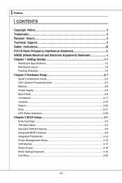
... 2-1 Quick Components Guide 2-2 CPU (Central Processing Unit 2-3 Memory 2-6 Power Supply 2-8 Back Panel 2-9 Connectors 2-11 Jumpers 2-19 Switch 2-20 Slots 2-21 LED Status Indicators 2-25 Chapter 3 BIOS Setup 3-1 Entering Setup 3-2 The Main Menu 3-4 Standard CMOS Features 3-6 Advanced BIOS Features 3-9 Integrated Peripherals 3-12 Power Management Setup 3-14 H/W Monitor 3-17 Green Power 3-18...
... 2-1 Quick Components Guide 2-2 CPU (Central Processing Unit 2-3 Memory 2-6 Power Supply 2-8 Back Panel 2-9 Connectors 2-11 Jumpers 2-19 Switch 2-20 Slots 2-21 LED Status Indicators 2-25 Chapter 3 BIOS Setup 3-1 Entering Setup 3-2 The Main Menu 3-4 Standard CMOS Features 3-6 Advanced BIOS Features 3-9 Integrated Peripherals 3-12 Power Management Setup 3-14 H/W Monitor 3-17 Green Power 3-18...

User Manual
Page 27
The system will be activated. To clear the warning, you must enter the BIOS utility and clear the record. 1.C2.IGNTroRuUnd 2-12 Chassis Intrusion Connector: JCI1 This connector connects to one Serial ATA device. If the chassis is a high-...
The system will be activated. To clear the warning, you must enter the BIOS utility and clear the record. 1.C2.IGNTroRuUnd 2-12 Chassis Intrusion Connector: JCI1 This connector connects to one Serial ATA device. If the chassis is a high-...
User Manual
Page 36
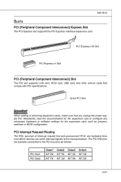
... pronounced I-R-Q, are typically connected to configure any necessary hardware or software settings for the expansion card to the PCI bus pins as jumpers, switches or BIOS configuration. Meanwhile, read the documentation for the expansion card, such as follows: PCI Slot1 PCI Slot2 Order1 INT E# INT F# Order2 INT F# INT G# Order3 INT G# INT...
... pronounced I-R-Q, are typically connected to configure any necessary hardware or software settings for the expansion card to the PCI bus pins as jumpers, switches or BIOS configuration. Meanwhile, read the documentation for the expansion card, such as follows: PCI Slot1 PCI Slot2 Order1 INT E# INT F# Order2 INT F# INT G# Order3 INT G# INT...

User Manual
Page 42
You may need to run the Setup program when: ■ An error message appears on the BIOS Setup program and allows you to run SETUP. ■ You want to configure the system for customized features. 2-3-1 Chapter 3 BIOS Setup This chapter provides information on the screen during the system booting up, and requests you to change the default settings for optimum use.
You may need to run the Setup program when: ■ An error message appears on the BIOS Setup program and allows you to run SETUP. ■ You want to configure the system for customized features. 2-3-1 Chapter 3 BIOS Setup This chapter provides information on the screen during the system booting up, and requests you to change the default settings for optimum use.
User Manual
Page 43
...8226; The items under continuous update for reference only. • Upon boot-up, the 1st line appearing after the memory count is usually in this BIOS was released. 3-2 Press DEL to enter SETUP If the message disappears before you respond and you still wish to enter Setup, restart the system by... simultaneously pressing , , and keys. It is the BIOS version. When the message below appears on the computer and the system will start POST (Power On Self Test) process. V1.0 refers to the...
...8226; The items under continuous update for reference only. • Upon boot-up, the 1st line appearing after the memory count is usually in this BIOS was released. 3-2 Press DEL to enter SETUP If the message disappears before you respond and you still wish to enter Setup, restart the system by... simultaneously pressing , , and keys. It is the BIOS version. When the message below appears on the computer and the system will start POST (Power On Self Test) process. V1.0 refers to the...

User Manual
Page 44
... a field parameter. If you can use arrow keys ( ↑↓ ) to highlight the field and press to call up the sub-menu. General Help The BIOS setup program provides a General Help screen. You can be launched from this screen from a submenu Increase the numeric value or make changes Decrease the numeric...
... a field parameter. If you can use arrow keys ( ↑↓ ) to highlight the field and press to call up the sub-menu. General Help The BIOS setup program provides a General Help screen. You can be launched from this screen from a submenu Increase the numeric value or make changes Decrease the numeric...

User Manual
Page 45
...; Standard CMOS Features Use this menu for basic system configurations, such as time, date etc. ▶ Advanced BIOS Features Use this menu to setup the items of the BIOS special enhanced features. ▶ Integrated Peripherals Use this menu to specify your settings for integrated peripherals. ▶ ... Monitor This entry shows your PC health status. ▶ Green Power Use this menu to specify the power phase. ▶ BIOS Setting Password Use this menu to set the password for BIOS. ▶ Cell Menu Use this menu to specify your settings for frequency/voltage control and overclocking. 3-4
...; Standard CMOS Features Use this menu for basic system configurations, such as time, date etc. ▶ Advanced BIOS Features Use this menu to setup the items of the BIOS special enhanced features. ▶ Integrated Peripherals Use this menu to specify your settings for integrated peripherals. ▶ ... Monitor This entry shows your PC health status. ▶ Green Power Use this menu to specify the power phase. ▶ BIOS Setting Password Use this menu to set the password for BIOS. ▶ Cell Menu Use this menu to specify your settings for frequency/voltage control and overclocking. 3-4
User Manual
Page 46
... storage drive (FAT/ FAT32 format only). ▶ Load Fail-Safe Defaults Use this menu to load the default values set by the BIOS vendor for stable system performance. ▶ Load Optimized Defaults Use this menu to load the default values set by the mainboard manufacturer specifically for optimal ...
... storage drive (FAT/ FAT32 format only). ▶ Load Fail-Safe Defaults Use this menu to load the default values set by the BIOS vendor for stable system performance. ▶ Load Optimized Defaults Use this menu to load the default values set by the mainboard manufacturer specifically for optimal ...

User Manual
Page 47
... date from 1 to 31 can be keyed by numeric function keys. [year] The year can be adjusted by BIOS. Read- The time format is . [day] Day of the week, from Jan. ▍ BIOS Setup Standard CMOS Features The items in Standard CMOS Features Menu include some basic setup items. Use the arrow...
... date from 1 to 31 can be keyed by numeric function keys. [year] The year can be adjusted by BIOS. Read- The time format is . [day] Day of the week, from Jan. ▍ BIOS Setup Standard CMOS Features The items in Standard CMOS Features Menu include some basic setup items. Use the arrow...

User Manual
Page 49
This sub-menu shows the CPU information, BIOS version and memory status of your system (read only). 3-8 ▍ BIOS Setup ▶ Hold on for any error is detected. [No Error] The system does not stop if an error is detected at boot. When the system stops for the errors preset, it will halt on The setting determines whether the system will stop for 15 seconds and then automatically resume its operation. [All Error] The system stops when any detected error. ▶ System Information Press to enter the sub-menu, and the following screen appears.
This sub-menu shows the CPU information, BIOS version and memory status of your system (read only). 3-8 ▍ BIOS Setup ▶ Hold on for any error is detected. [No Error] The system does not stop if an error is detected at boot. When the system stops for the errors preset, it will halt on The setting determines whether the system will stop for 15 seconds and then automatically resume its operation. [All Error] The system stops when any detected error. ▶ System Information Press to enter the sub-menu, and the following screen appears.

User Manual
Page 50
...▶ Boot Up Num-Lock LED This setting is to show the company logo on . When enabled, the BIOS' data cannot be changed when attempting to disable this Flash BIOS Protection function. You should immediately re-enable it to protect it is when you should enable this system to set... when the system is powered on the full screen at boot. [Disabled] Shows the POST messages at all times. To successfully update the BIOS, you need to update the BIOS with a Flash utility. Settings are: [Enabled] Shows a still image (logo) on . Setting to [Off] will need to disable it against ...
...▶ Boot Up Num-Lock LED This setting is to show the company logo on . When enabled, the BIOS' data cannot be changed when attempting to disable this Flash BIOS Protection function. You should immediately re-enable it to protect it is when you should enable this system to set... when the system is powered on the full screen at boot. [Disabled] Shows the POST messages at all times. To successfully update the BIOS, you need to update the BIOS with a Flash utility. Settings are: [Enabled] Shows a still image (logo) on . Setting to [Off] will need to disable it against ...
User Manual
Page 51
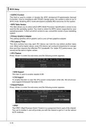
▍ BIOS Setup ▶ IOAPIC Function This field is used for the operating system. Due to compliance with the means to get to run in APIC mode. ...
▍ BIOS Setup ▶ IOAPIC Function This field is used for the operating system. Due to compliance with the means to get to run in APIC mode. ...
User Manual
Page 52
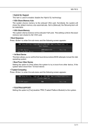
... to enter the sub-menu and the following screen appears: ▶ 1st Boot Device This item allows you to set the first boot device where BIOS attempts to load the disk operating system. ▶ Boot From Other Device Setting the option to [Yes] allows the system to try to boot from...
... to enter the sub-menu and the following screen appears: ▶ 1st Boot Device This item allows you to set the first boot device where BIOS attempts to load the disk operating system. ▶ Boot From Other Device Setting the option to [Yes] allows the system to try to boot from...

User Manual
Page 53
▍ BIOS Setup Integrated Peripherals ▶ USB Controller This setting allows you to enable/disable the onboard USB 1.1/ 2.0 controller. ▶ USB Device Legacy Support Select [Enabled] if ...
▍ BIOS Setup Integrated Peripherals ▶ USB Controller This setting allows you to enable/disable the onboard USB 1.1/ 2.0 controller. ▶ USB Device Legacy Support Select [Enabled] if ...

User Manual
Page 54
... the ECP and EPP modes simultaneously. 3-13 Select [Enabled] to activate the IDE interface. ▶ PCI IDE BusMaster This item allows you to enable/ disable BIOS to used PCI busmastering for reading/ writing to IDE drives. ▶ On-Chip SATA Controller This item allows users to enable or disable the SATA...
... the ECP and EPP modes simultaneously. 3-13 Select [Enabled] to activate the IDE interface. ▶ PCI IDE BusMaster This item allows you to enable/ disable BIOS to used PCI busmastering for reading/ writing to IDE drives. ▶ On-Chip SATA Controller This item allows users to enable or disable the SATA...

User Manual
Page 55
...a lower power state where the in formation of this field. The information stored in memory will be used to save energy. ▍ BIOS Setup Power Management Setup Important S3-related functions described in this state, no system context is lost (CPU or chipset) and hardware maintains all... sys- Settings are available only when the BIOS supports S3 sleep mode. ▶ ACPI Function This item is to activate the ACPI (Advanced Configuration and Power Management Interface) Function. If ...
...a lower power state where the in formation of this field. The information stored in memory will be used to save energy. ▍ BIOS Setup Power Management Setup Important S3-related functions described in this state, no system context is lost (CPU or chipset) and hardware maintains all... sys- Settings are available only when the BIOS supports S3 sleep mode. ▶ ACPI Function This item is to activate the ACPI (Advanced Configuration and Power Management Interface) Function. If ...

User Manual
Page 56
... before power failure or interrupt occurred. ▶ Wake Up Event Setup Press and the following sub-menu appears. ▶ Wake up Event By Setting to [BIOS] activates the following fields, and use the following fields to [OS], the wake up events will be awakened from S3 (Suspend to RAM) sleep state...
... before power failure or interrupt occurred. ▶ Wake Up Event Setup Press and the following sub-menu appears. ▶ Wake up Event By Setting to [BIOS] activates the following fields, and use the following fields to [OS], the wake up events will be awakened from S3 (Suspend to RAM) sleep state...

User Manual
Page 57
Available settings for each item are: [Date] 01 ~ 31, Every Day [Time (HH:MM:SS)] 00 ~ 23 : 00 ~ 59 : 00 ~ 59 3-16 ▍ BIOS Setup ▶ Resume By Onboard LAN This fields specify whether the system will be awakened from power saving modes when activity or input signal of ...
Available settings for each item are: [Date] 01 ~ 31, Every Day [Time (HH:MM:SS)] 00 ~ 23 : 00 ~ 59 : 00 ~ 59 3-16 ▍ BIOS Setup ▶ Resume By Onboard LAN This fields specify whether the system will be awakened from power saving modes when activity or input signal of ...
User Manual
Page 59
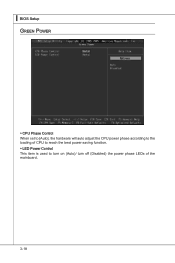
▍ BIOS Setup Green Power ▶ CPU Phase Control When set to [Auto], the hardware will auto adjust the CPU power phase according to the loading of CPU to reach the best power saving function. ▶ LED Power Control This item is used to turn on (Auto)/ turn off (Disabled) the power phase LEDs of the mainboard. 3-18
▍ BIOS Setup Green Power ▶ CPU Phase Control When set to [Auto], the hardware will auto adjust the CPU power phase according to the loading of CPU to reach the best power saving function. ▶ LED Power Control This item is used to turn on (Auto)/ turn off (Disabled) the power phase LEDs of the mainboard. 3-18


