User Manual
Page 8
... (Waste Electrical and Electronic Equipment) Statement v Chapter 1 Getting Started 1-1 Mainboard Specifications 1-2 Mainboard Layout 1-4 Packing Checklist 1-5 Chapter 2 Hardware Setup 2-1 Quick Components Guide 2-2 CPU (Central Processing Unit 2-3 Memory 2-6 Power Supply 2-8 Back Panel 2-9 Connectors 2-11 Jumpers 2-19 Switch 2-20 Slots 2-21 LED Status Indicators 2-25 Chapter 3 BIOS Setup 3-1 Entering Setup 3-2 The Main Menu 3-4 Standard...
... (Waste Electrical and Electronic Equipment) Statement v Chapter 1 Getting Started 1-1 Mainboard Specifications 1-2 Mainboard Layout 1-4 Packing Checklist 1-5 Chapter 2 Hardware Setup 2-1 Quick Components Guide 2-2 CPU (Central Processing Unit 2-3 Memory 2-6 Power Supply 2-8 Back Panel 2-9 Connectors 2-11 Jumpers 2-19 Switch 2-20 Slots 2-21 LED Status Indicators 2-25 Chapter 3 BIOS Setup 3-1 Entering Setup 3-2 The Main Menu 3-4 Standard...
User Manual
Page 11
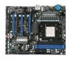
...the AM3 package. (For the latest information about CPU, please visit http://www.msi.com/index. php?func=cpuform2) HyperTransport ■ HyperTransport™ 3.0, supports up to 2.6 GHz Chipset ■ NVIDIA® nForce 980A SLI chipset Memory Support ■ DDR3 *(OC) 2133/ 1800/ 1600/ 1333/ 1066/ 800 ...SDRAM (total 16 GB Max) ■ 4 DDR3 DIMMs (240-pin/ 1.5V) *(For more information on compatible components, please visit http://www.msi.com/index.php?func=testreport) LAN ■...
...the AM3 package. (For the latest information about CPU, please visit http://www.msi.com/index. php?func=cpuform2) HyperTransport ■ HyperTransport™ 3.0, supports up to 2.6 GHz Chipset ■ NVIDIA® nForce 980A SLI chipset Memory Support ■ DDR3 *(OC) 2133/ 1800/ 1600/ 1333/ 1066/ 800 ...SDRAM (total 16 GB Max) ■ 4 DDR3 DIMMs (240-pin/ 1.5V) *(For more information on compatible components, please visit http://www.msi.com/index.php?func=testreport) LAN ■...

User Manual
Page 21
For more information on compatible components, please visit http://www.msi.com/index.php?func=testreport DDR3 240-pin, 1.5V 72x2=144 pin 48x2=96 pin Dual-Channel mode Population Rule In Dual-Channel mode, the memory modules can enhance the system performance. Enabling Dual-Channel mode can transmit and receive data with... of the same type and density in different channel DIMM slots. • To enable successful system boot-up, always insert the memory modules into the DIMM1 first. • Due to the chipset resource deployment, the system density will only be detected up to 15+GB (not full ...
For more information on compatible components, please visit http://www.msi.com/index.php?func=testreport DDR3 240-pin, 1.5V 72x2=144 pin 48x2=96 pin Dual-Channel mode Population Rule In Dual-Channel mode, the memory modules can enhance the system performance. Enabling Dual-Channel mode can transmit and receive data with... of the same type and density in different channel DIMM slots. • To enable successful system boot-up, always insert the memory modules into the DIMM1 first. • Due to the chipset resource deployment, the system density will only be detected up to 15+GB (not full ...

User Manual
Page 22
... has been locked in place by the DIMM slot clips at each side of the DIMM slot will automatically close when the memory module is deeply inserted in until the golden finger on the center and will only fit in the DIMM slot. Then push it in the ...DIMM slot. Notch Volt 2-7 The plastic clip at the sides. The memory module has only one notch on the memory module is properly seated. 3. Important You can barely see the golden finger if the...
... has been locked in place by the DIMM slot clips at each side of the DIMM slot will automatically close when the memory module is deeply inserted in until the golden finger on the center and will only fit in the DIMM slot. Then push it in the ...DIMM slot. Notch Volt 2-7 The plastic clip at the sides. The memory module has only one notch on the memory module is properly seated. 3. Important You can barely see the golden finger if the...
User Manual
Page 43
... may be slightly different from the latest BIOS and should be held for reference only. • Upon boot-up, the 1st line appearing after the memory count is usually in this BIOS was released. 3-2 It is the BIOS version. Important • The items under each BIOS category described in the format...
... may be slightly different from the latest BIOS and should be held for reference only. • Upon boot-up, the 1st line appearing after the memory count is usually in this BIOS was released. 3-2 It is the BIOS version. Important • The items under each BIOS category described in the format...

User Manual
Page 49
This sub-menu shows the CPU information, BIOS version and memory status of your system (read only). 3-8 When the system stops for the errors preset, it will halt on The setting determines whether the system will stop if an error is detected. [No Error] The system does not stop for 15 seconds and then automatically resume its operation. [All Error] The system stops when any error is detected at boot. ▍ BIOS Setup ▶ Hold on for any detected error. ▶ System Information Press to enter the sub-menu, and the following screen appears.
This sub-menu shows the CPU information, BIOS version and memory status of your system (read only). 3-8 When the system stops for the errors preset, it will halt on The setting determines whether the system will stop if an error is detected. [No Error] The system does not stop for 15 seconds and then automatically resume its operation. [All Error] The system stops when any error is detected at boot. ▍ BIOS Setup ▶ Hold on for any detected error. ▶ System Information Press to enter the sub-menu, and the following screen appears.
User Manual
Page 52
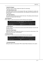
Set to the onboard VGA card. Set [Auto], the system will be selectable. ▶ VGA Share Memory The system shares memory to [Manual], the following screen appears: ▶ TCG/TPM SUPPORT Setting the option to [Yes] enables TPM (Trusted Platform Module) to the onboard VGA card....▶ Hybrid SLI Support This item is used to enable/ disable the Hybrid SLI technology. ▶ VGA Share Memory Auto The system shares memory to the system. 3-11 This setting controls the exact memory size shared to the VGA card. ▶ Boot Sequence Press to enter the sub-menu and the following screen...
Set to the onboard VGA card. Set [Auto], the system will be selectable. ▶ VGA Share Memory The system shares memory to [Manual], the following screen appears: ▶ TCG/TPM SUPPORT Setting the option to [Yes] enables TPM (Trusted Platform Module) to the onboard VGA card....▶ Hybrid SLI Support This item is used to enable/ disable the Hybrid SLI technology. ▶ VGA Share Memory Auto The system shares memory to the system. 3-11 This setting controls the exact memory size shared to the VGA card. ▶ Boot Sequence Press to enter the sub-menu and the following screen...

User Manual
Page 55
... mode is a low power state. Settings are available only when the BIOS supports S3 sleep mode. ▶ ACPI Function This item is saved to main memory that remains powered while most other hardware components turn off to restore the system when a "wake up" event occurs. 3-14 The information stored in S1...(POS) or S3(STR) fashion through the setting of system configuration and open applications/files is to enter the Standby mode in memory will be used to save energy.
... mode is a low power state. Settings are available only when the BIOS supports S3 sleep mode. ▶ ACPI Function This item is saved to main memory that remains powered while most other hardware components turn off to restore the system when a "wake up" event occurs. 3-14 The information stored in S1...(POS) or S3(STR) fashion through the setting of system configuration and open applications/files is to enter the Standby mode in memory will be used to save energy.

User Manual
Page 60
... to enter it every time you can enter Setup without entering any part of your system configuration. 3-19 This prevents an unauthorized person from CMOS memory. When a password has been set password, just press when you are prompted to enter Setup. Retype the password and press . You may also press to...
... to enter it every time you can enter Setup without entering any part of your system configuration. 3-19 This prevents an unauthorized person from CMOS memory. When a password has been set password, just press when you are prompted to enter Setup. Retype the password and press . You may also press to...

User Manual
Page 61
This submenu shows the information of CPU and Memory speed. Read-only. ▶ CPU Specifications Press to enter the sub-menu and the following screen appears. ▍ BIOS Setup Cell Menu Important Change these settings only if you are familiar with the chipset. ▶ Current CPU / DRAM Frequency These items show the current clocks of installed CPU. 3-20
This submenu shows the information of CPU and Memory speed. Read-only. ▶ CPU Specifications Press to enter the sub-menu and the following screen appears. ▍ BIOS Setup Cell Menu Important Change these settings only if you are familiar with the chipset. ▶ Current CPU / DRAM Frequency These items show the current clocks of installed CPU. 3-20

User Manual
Page 63
...timing. ▶ DRAM Drive Strength This item allows you to adjust CPU clock multiplier (ratio). Setting to [Enabled] allows you to control the memory data bus' signal strength. ▍ BIOS Setup ▶ Adjust CPU FSB Frequency (MHz) This item allows you to select the CPU Front ...the adjusted CPU NB frequency. It is available only when the processor supports this function. ▶ Memory-Z Press to enter the sub-menu and the following screen appears. ▶ DIMM1~4 Memory SPD Information Press to enter the sub-menu and the following screen appears. ▶ DRAM Timing Mode...
...timing. ▶ DRAM Drive Strength This item allows you to adjust CPU clock multiplier (ratio). Setting to [Enabled] allows you to control the memory data bus' signal strength. ▍ BIOS Setup ▶ Adjust CPU FSB Frequency (MHz) This item allows you to select the CPU Front ...the adjusted CPU NB frequency. It is available only when the processor supports this function. ▶ Memory-Z Press to enter the sub-menu and the following screen appears. ▶ DIMM1~4 Memory SPD Information Press to enter the sub-menu and the following screen appears. ▶ DRAM Timing Mode...
User Manual
Page 64
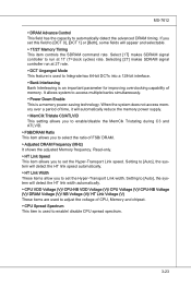
... Link Width These items allow you to run at 1T (T=clock cycles) rate. Setting to [Auto], the system will automatically reduce the memory power supply. ▶ MemClk Tristate C3/ATLVID This setting allows you to enable/disable the MemClk Tristating during C3 and ATLVID. ▶... Bank Interleaving is an important parameter for improving overclocking capability of FSB/ DRAM. ▶ Adjusted DRAM Frequency (MHz) It shows the adjusted Memory frequency. Select [1T] makes SDRAM signal controller to set the Hyper-Transport Link width. Read-only. ▶ HT Link Speed This item...
... Link Width These items allow you to run at 1T (T=clock cycles) rate. Setting to [Auto], the system will automatically reduce the memory power supply. ▶ MemClk Tristate C3/ATLVID This setting allows you to enable/disable the MemClk Tristating during C3 and ATLVID. ▶... Bank Interleaving is an important parameter for improving overclocking capability of FSB/ DRAM. ▶ Adjusted DRAM Frequency (MHz) It shows the adjusted Memory frequency. Select [1T] makes SDRAM signal controller to set the Hyper-Transport Link width. Read-only. ▶ HT Link Speed This item...

User Manual
Page 112
DotNet Frame Work 2.0 B-C-1 Appendix C Overclocking Center Overclocking Center, the most useful and powerful utility that MSI has spent much research and efforts to develop, helps users to monitor or configure the hardware status of MSI Mainboard in windows, such as CPU clock, voltage, fan speed and temperature. DVD-ROM drive for software installation. 3. Operation system: Windows XP or up. 4. Before you install the Overclocking Center, please make sure the system has meet the following requirements: 1. 256MB system memory. 2.
DotNet Frame Work 2.0 B-C-1 Appendix C Overclocking Center Overclocking Center, the most useful and powerful utility that MSI has spent much research and efforts to develop, helps users to monitor or configure the hardware status of MSI Mainboard in windows, such as CPU clock, voltage, fan speed and temperature. DVD-ROM drive for software installation. 3. Operation system: Windows XP or up. 4. Before you install the Overclocking Center, please make sure the system has meet the following requirements: 1. 256MB system memory. 2.
User Manual
Page 114
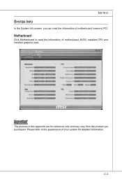
Please refer to read the information of motherboard/ memory/ PCI. Important The pictures in this appendix are for detailed information. C-3 Motherboard Click Motherboard to the appearance of your system for reference only and may vary from the product you can read the information of motherboard, BIOS, installed CPU and installed graphics card. MS-7612 System Info In the System Info screen, you purchased.
Please refer to read the information of motherboard/ memory/ PCI. Important The pictures in this appendix are for detailed information. C-3 Motherboard Click Motherboard to the appearance of your system for reference only and may vary from the product you can read the information of motherboard, BIOS, installed CPU and installed graphics card. MS-7612 System Info In the System Info screen, you purchased.


