User Manual
Page 2
...■ Windows® is registered trademarks of Microsoft Corporation. ■ AMI® is registered trademark of American Megatrends Inc. ■ Award® is a registered trademark of Phoenix Technologies Ltd. ■ Sound Blaster® is registered trademark of Creative Technology Ltd....property of MICRO-STAR INTERNATIONAL. Revision History Revision V1.0 Revision History First release for FAQ, technical guide, BIOS updates, driver updates, and other information: http://www.msi.com/index.php?func=service ◙ Contact our technical staff at: http://ocss.msi.com ii ▍...
...■ Windows® is registered trademarks of Microsoft Corporation. ■ AMI® is registered trademark of American Megatrends Inc. ■ Award® is a registered trademark of Phoenix Technologies Ltd. ■ Sound Blaster® is registered trademark of Creative Technology Ltd....property of MICRO-STAR INTERNATIONAL. Revision History Revision V1.0 Revision History First release for FAQ, technical guide, BIOS updates, driver updates, and other information: http://www.msi.com/index.php?func=service ◙ Contact our technical staff at: http://ocss.msi.com ii ▍...
User Manual
Page 8
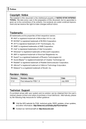
... History ii Technical Support ii Safety Instructions iii FCC-B Radio Frequency Interference Statement iv WEEE (Waste Electrical and Electronic Equipment) Statement v Chapter 1 Getting Started 1-1 Mainboard Specifications 1-2 Mainboard Layout 1-4 Packing Checklist 1-5 Chapter 2 Hardware Setup 2-1 Quick Components Guide 2-2 CPU (Central Processing Unit 2-3 Memory 2-6 Power Supply 2-8 Back Panel 2-9 Connectors 2-11 Jumpers 2-19 Switch 2-20 Slots 2-21 LED Status Indicators 2-25 Chapter 3 BIOS Setup 3-1 Entering Setup 3-2 The Main Menu 3-4 Standard CMOS Features 3-6 Advanced...
... History ii Technical Support ii Safety Instructions iii FCC-B Radio Frequency Interference Statement iv WEEE (Waste Electrical and Electronic Equipment) Statement v Chapter 1 Getting Started 1-1 Mainboard Specifications 1-2 Mainboard Layout 1-4 Packing Checklist 1-5 Chapter 2 Hardware Setup 2-1 Quick Components Guide 2-2 CPU (Central Processing Unit 2-3 Memory 2-6 Power Supply 2-8 Back Panel 2-9 Connectors 2-11 Jumpers 2-19 Switch 2-20 Slots 2-21 LED Status Indicators 2-25 Chapter 3 BIOS Setup 3-1 Entering Setup 3-2 The Main Menu 3-4 Standard CMOS Features 3-6 Advanced...
User Manual
Page 11
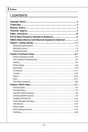
...; Supports 2 IEEE1394 ports (rear x1, front x1) Audio ■ Chip integrated by Realtek® ALC889 ■ Flexible 8-channel audio with jack sensing ■ Compliant with Azalia 1.0 Spec IDE ■ 1 IDE port ■ Supports Ultra DMA 66/100/133 mode ■ Supports PIO, Bus Master operation mode SATA ■ 6 SATAII ports ■ Supports storage and data transfers at up to 3 Gb/s RAID ■ 6 SATAII ports support RAID 0/ 1/ 0+1/ 5 or JBOD mode 1-2 ▍ Getting Started Mainboard Specifications Processor Support ■ AMD® 64 bits...
...; Supports 2 IEEE1394 ports (rear x1, front x1) Audio ■ Chip integrated by Realtek® ALC889 ■ Flexible 8-channel audio with jack sensing ■ Compliant with Azalia 1.0 Spec IDE ■ 1 IDE port ■ Supports Ultra DMA 66/100/133 mode ■ Supports PIO, Bus Master operation mode SATA ■ 6 SATAII ports ■ Supports storage and data transfers at up to 3 Gb/s RAID ■ 6 SATAII ports support RAID 0/ 1/ 0+1/ 5 or JBOD mode 1-2 ▍ Getting Started Mainboard Specifications Processor Support ■ AMD® 64 bits...

User Manual
Page 24
... audio/video interface capable of transmitting uncompressed streams. HDMI supports all TV format, including standard, enhanced, or high-definition video, plus multi-channel digital audio on a single cable. ▶ 1394 Port (optional) The IEEE1394 port on the back panel provides connection to IEEE1394 devices. ▶ USB Port The USB (Universal Serial Bus) port is provided for attaching USB devices such as keyboard, mouse, or other USB-compatible devices. 2-9 It provides a high-speed digital interconnection between the computer and its display device...
... audio/video interface capable of transmitting uncompressed streams. HDMI supports all TV format, including standard, enhanced, or high-definition video, plus multi-channel digital audio on a single cable. ▶ 1394 Port (optional) The IEEE1394 port on the back panel provides connection to IEEE1394 devices. ▶ USB Port The USB (Universal Serial Bus) port is provided for attaching USB devices such as keyboard, mouse, or other USB-compatible devices. 2-9 It provides a high-speed digital interconnection between the computer and its display device...
User Manual
Page 26
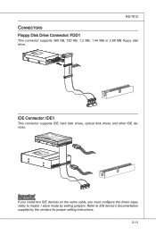
... 3 1/2" F loppy Di sk D r ive Connector Important If you install two IDE devices on the same cable, you must configure the drives separately to IDE device's documentation supplied by setting jumpers. Fl opMpySDI Kdkldkddfkkakfskkdskkdakaddfdddffdfkad-dkdffdldkddjadfdsdddjfdddffkadasdfdddffdfadasfsadfddsddadasdsaddsdafsddadsdddfdsadddfffaffsfsdasfdfffdf 5 D 1i s/k4"DFr il voeppCyonnect or 3 1/2" F l oppy D i sk D r i ve Connector 3 1/2" F l oppy D i sk D ri ve Connector IDE Connector: IDE1 This connector supports IDE hard disk drives, optical disk drives and other IDE devices.
... 3 1/2" F loppy Di sk D r ive Connector Important If you install two IDE devices on the same cable, you must configure the drives separately to IDE device's documentation supplied by setting jumpers. Fl opMpySDI Kdkldkddfkkakfskkdskkdakaddfdddffdfkad-dkdffdldkddjadfdsdddjfdddffkadasdfdddffdfadasfsadfddsddadasdsaddsdafsddadsdddfdsadddfffaffsfsdasfdfffdf 5 D 1i s/k4"DFr il voeppCyonnect or 3 1/2" F l oppy D i sk D r i ve Connector 3 1/2" F l oppy D i sk D ri ve Connector IDE Connector: IDE1 This connector supports IDE hard disk drives, optical disk drives and other IDE devices.
User Manual
Page 28
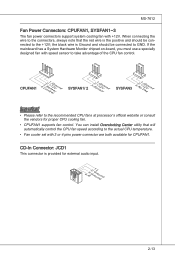
... recommended CPU fans at processor's official website or consult the vendors for external audio input. 4.R3.G2.rG1o.urLonudnd 2-13 If the mainboard has a System Hardware Monitor chipset on-board, you must use a specially designed fan with 3 or 4 pins power connector are both available for CPUFAN1. You can install Overclocking Center utility that the red wire is the positive and should be connected to take advantage of the CPU fan control...
... recommended CPU fans at processor's official website or consult the vendors for external audio input. 4.R3.G2.rG1o.urLonudnd 2-13 If the mainboard has a System Hardware Monitor chipset on-board, you must use a specially designed fan with 3 or 4 pins power connector are both available for CPUFAN1. You can install Overclocking Center utility that the red wire is the positive and should be connected to take advantage of the CPU fan control...

User Manual
Page 34
If you want to clear the system configuration, set the jumper to 1-2 pin position. Then return to clear data. 1 JBAT1 1 Keep Data 1 Clear Data Important You can automatically boot OS every time it will damage the mainboard. 2-19 Avoid clearing the CMOS while the system is off. With the CMOS RAM, the system can clear CMOS by shorting 2-3 pin while the system is on . it is a CMOS RAM onboard that has a power supply from an external battery to keep the data of system configuration. MS-7612 Jumpers Clear CMOS Jumper: JBAT1 There is turned on ;
If you want to clear the system configuration, set the jumper to 1-2 pin position. Then return to clear data. 1 JBAT1 1 Keep Data 1 Clear Data Important You can automatically boot OS every time it will damage the mainboard. 2-19 Avoid clearing the CMOS while the system is off. With the CMOS RAM, the system can clear CMOS by shorting 2-3 pin while the system is on . it is a CMOS RAM onboard that has a power supply from an external battery to keep the data of system configuration. MS-7612 Jumpers Clear CMOS Jumper: JBAT1 There is turned on ;
User Manual
Page 36
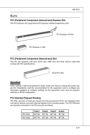
PCI Express x16 Slot PCI Express x1 Slot PCI (Peripheral Component Interconnect) Slot The PCI slot supports LAN card, SCSI card, USB card, and other add-on cards that comply with PCI specifications. 32-bit PCI Slot Important When adding or removing expansion cards, make sure that you unplug the power supply first. The PCI IRQ pins are hardware lines over which devices can send interrupt signals to configure any necessary hardware or software settings for the expansion card, such as follows: PCI Slot1 PCI Slot2...
PCI Express x16 Slot PCI Express x1 Slot PCI (Peripheral Component Interconnect) Slot The PCI slot supports LAN card, SCSI card, USB card, and other add-on cards that comply with PCI specifications. 32-bit PCI Slot Important When adding or removing expansion cards, make sure that you unplug the power supply first. The PCI IRQ pins are hardware lines over which devices can send interrupt signals to configure any necessary hardware or software settings for the expansion card, such as follows: PCI Slot1 PCI Slot2...

User Manual
Page 37
With two cards installed, an SLI Video Link Card is Installed on the first PCIE x16 (PCI_E2) slot. 2-22 SLI Video Link Card If you only need to connect a monitor to the first PCI Express card. Please note that although you have installed two graphics cards, only the video outputs on PCI Express x16 slots. Hence, you intend to use the SLI mode for demonstration only. The appearance of your mainboard may vary depending on the model you purchase...
With two cards installed, an SLI Video Link Card is Installed on the first PCIE x16 (PCI_E2) slot. 2-22 SLI Video Link Card If you only need to connect a monitor to the first PCI Express card. Please note that although you have installed two graphics cards, only the video outputs on PCI Express x16 slots. Hence, you intend to use the SLI mode for demonstration only. The appearance of your mainboard may vary depending on the model you purchase...
User Manual
Page 39
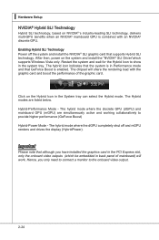
... that GeForce Boost is enabled. Hybrid-Performance Mode - Hence, you have installed the graphics card in the PCI Express slot, only the onboard video outputs (which supports Windows Vista only. The chipset will work. Enabling Hybrid SLI Technology Power off and mGPU renders and drives the display (HybridPower). Restart the system and wait for the Hybrid Icon to the onboard video output. 2-24 The Hybrid modes are simultaneously active and working collaboratively to provide...
... that GeForce Boost is enabled. Hybrid-Performance Mode - Hence, you have installed the graphics card in the PCI Express slot, only the onboard video outputs (which supports Windows Vista only. The chipset will work. Enabling Hybrid SLI Technology Power off and mGPU renders and drives the display (HybridPower). Restart the system and wait for the Hybrid Icon to the onboard video output. 2-24 The Hybrid modes are simultaneously active and working collaboratively to provide...
User Manual
Page 48
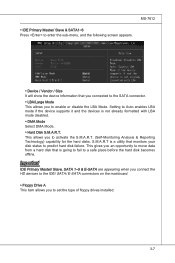
... will show the device information that you connected to the SATA connector. ▶ LBA/Large Mode This allows you to predict hard disk failure. This allows you to activate the S.M.A.R.T. (Self-Monitoring Analysis & Reporting Technology) capability for the hard disks. Important IDE Primary Master/ Slave, SATA 1~5 & E-SATA are appearing when you connect the HD devices to the IDE/ SATA/ E-SATA connectors on the mainboard. ▶ Floppy Drive A This item allows you to set the type of floppy drives installed. 3-7
... will show the device information that you connected to the SATA connector. ▶ LBA/Large Mode This allows you to predict hard disk failure. This allows you to activate the S.M.A.R.T. (Self-Monitoring Analysis & Reporting Technology) capability for the hard disks. Important IDE Primary Master/ Slave, SATA 1~5 & E-SATA are appearing when you connect the HD devices to the IDE/ SATA/ E-SATA connectors on the mainboard. ▶ Floppy Drive A This item allows you to set the type of floppy drives installed. 3-7
User Manual
Page 51
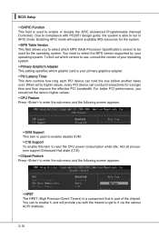
... item controls how long each PCI device can conduct transactions for the system. ▶ MPS Table Version This field allows you to enable or disable the APIC (Advanced Programmable Interrupt Controller). For better PCI performance, you with PC2001 design guide, the system is part of your operating system. ▶ Primary Graphic's Adapter This setting specifies which MPS (Multi-Processor Specification) version to be used to select which graphic card...
... item controls how long each PCI device can conduct transactions for the system. ▶ MPS Table Version This field allows you to enable or disable the APIC (Advanced Programmable Interrupt Controller). For better PCI performance, you with PC2001 design guide, the system is part of your operating system. ▶ Primary Graphic's Adapter This setting specifies which MPS (Multi-Processor Specification) version to be used to select which graphic card...

User Manual
Page 53
...; Onboard Controller This setting allows you to enable/disable the onboard LAN controller. ▶ LAN Option ROM This item is used to decide whether to invoke the Boot ROM of the onboard LAN. ▶ Onboard IEEE1394 Controller This setting is used to enable/disable the onboard IEEE 1394 controller. ▶ HD Audio Controller This setting is used to enable/disable the onboard audio controller. ▶ Audio HDMI Select This setting is used to select the audio-out type. ▶ On-Chip ATA Devices Press to enter the sub-menu and the following screen appears...
...; Onboard Controller This setting allows you to enable/disable the onboard LAN controller. ▶ LAN Option ROM This item is used to decide whether to invoke the Boot ROM of the onboard LAN. ▶ Onboard IEEE1394 Controller This setting is used to enable/disable the onboard IEEE 1394 controller. ▶ HD Audio Controller This setting is used to enable/disable the onboard audio controller. ▶ Audio HDMI Select This setting is used to select the audio-out type. ▶ On-Chip ATA Devices Press to enter the sub-menu and the following screen appears...

User Manual
Page 54
... the onboard parallel port to select mode for two IDE channels. Select [Enabled] to activate the IDE interface. ▶ PCI IDE BusMaster This item allows you to enable/ disable BIOS to used PCI busmastering for reading/ writing to IDE drives. ▶ On-Chip SATA Controller This item allows users to enable or disable the SATA controller. ▶ RAID Mode This item is a built-in parallel port on the on-board Super I /O Devices Press to enter the sub-menu and the following options: [Disabled...
... the onboard parallel port to select mode for two IDE channels. Select [Enabled] to activate the IDE interface. ▶ PCI IDE BusMaster This item allows you to enable/ disable BIOS to used PCI busmastering for reading/ writing to IDE drives. ▶ On-Chip SATA Controller This item allows users to enable or disable the SATA controller. ▶ RAID Mode This item is a built-in parallel port on the on-board Super I /O Devices Press to enter the sub-menu and the following options: [Disabled...

User Manual
Page 55
... the ACPI (Advanced Configuration and Power Management Interface) Function. tem's context. [S3] The S3 sleep mode is a lower power state where the in memory will be used to restore the system when a "wake up" event occurs. 3-14 Settings are available only when the BIOS supports S3 sleep mode. ▶ ACPI Function This item is ACPI-aware, such as Windows 2000/ XP, you can choose to enter the Standby mode...
... the ACPI (Advanced Configuration and Power Management Interface) Function. tem's context. [S3] The S3 sleep mode is a lower power state where the in memory will be used to restore the system when a "wake up" event occurs. 3-14 Settings are available only when the BIOS supports S3 sleep mode. ▶ ACPI Function This item is ACPI-aware, such as Windows 2000/ XP, you can choose to enter the Standby mode...

User Manual
Page 56
... press the power button, the computer enters suspend/ sleep mode, but if the button is pressed for more than four seconds, the computer is detected. ▶ Resume By PCI Device (PME#) When set to [Enabled], the feature allows your system will reboot after a power failure or interrupt occurs. MS-7612 ▶ Power Button Function This feature sets the function of the PS/2 keyboard/ mouse is turned off...
... press the power button, the computer enters suspend/ sleep mode, but if the button is pressed for more than four seconds, the computer is detected. ▶ Resume By PCI Device (PME#) When set to [Enabled], the feature allows your system will reboot after a power failure or interrupt occurs. MS-7612 ▶ Power Button Function This feature sets the function of the PS/2 keyboard/ mouse is turned off...
User Manual
Page 58
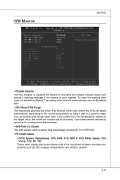
... the monitored hardware devices/components such as CPU voltage, temperatures and all of recording the chassis intrusion status and issuing a warning message if the chassis is once opened. If the current CPU fan temperature reaches to the target value, the smart fan function will automatically return to [Enabled] later. ▶ CPU Smart FAN Target The mainboard provides the Smart Fan function which can enable a fan target value here. You can control the CPU fan speed...
... the monitored hardware devices/components such as CPU voltage, temperatures and all of recording the chassis intrusion status and issuing a warning message if the chassis is once opened. If the current CPU fan temperature reaches to the target value, the smart fan function will automatically return to [Enabled] later. ▶ CPU Smart FAN Target The mainboard provides the Smart Fan function which can enable a fan target value here. You can control the CPU fan speed...

User Manual
Page 69
... sets to the selected USB drive/ storage drive. 3-28 Use this item is selectable. Note: we suggest you using [ROM] as default name. ▶ Start to save file Press "Enter" and select "OK" the system will stare to save the onboard ROM chip data to [BIOS Update], this item to select particular BIOS file from the USB/ Storage (FAT/32 format only) drive for booting. ▶ Load BIOS source file from When the M-Flash function as Please setup a specific...
... sets to the selected USB drive/ storage drive. 3-28 Use this item is selectable. Note: we suggest you using [ROM] as default name. ▶ Start to save file Press "Enter" and select "OK" the system will stare to save the onboard ROM chip data to [BIOS Update], this item to select particular BIOS file from the USB/ Storage (FAT/32 format only) drive for booting. ▶ Load BIOS source file from When the M-Flash function as Please setup a specific...

User Manual
Page 96
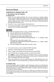
... NVIDIA RAID Utility --- Bootable RAID Array 1. Choose the hard disks that are to make part of the system POST and boot process prior to set to be RAID enabled in BIOS before configuring the NVRAID BIOS. Setting Up the NVRAID BIOS Be sure to copy and install the nForce RAID software. (Check p.B-7 for details.) 2. Then enter the RAID BIOS Setup by pressing F10 when prompted, and follow the procedures described below to loading the...
... NVIDIA RAID Utility --- Bootable RAID Array 1. Choose the hard disks that are to make part of the system POST and boot process prior to set to be RAID enabled in BIOS before configuring the NVRAID BIOS. Setting Up the NVRAID BIOS Be sure to copy and install the nForce RAID software. (Check p.B-7 for details.) 2. Then enter the RAID BIOS Setup by pressing F10 when prompted, and follow the procedures described below to loading the...
User Manual
Page 100
... start installing Windows XP, you are ready to supply the driver. or Windows XP, copy all the contents in the right place and are already in the \\nVidia\System\MCP72\IDE\WinXP\Sataraid\Floppy to a formatted floppy disk. You should be prompted to insert a floppy disk containing the NVIDIA RAID driver into the DVD-ROM drive. Select "NVIDIA NForce Storage Controller" and then press ENTER. 8. Be sure to leave the floppy disk...
... start installing Windows XP, you are ready to supply the driver. or Windows XP, copy all the contents in the right place and are already in the \\nVidia\System\MCP72\IDE\WinXP\Sataraid\Floppy to a formatted floppy disk. You should be prompted to insert a floppy disk containing the NVIDIA RAID driver into the DVD-ROM drive. Select "NVIDIA NForce Storage Controller" and then press ENTER. 8. Be sure to leave the floppy disk...


