
User Manual
Page 4
...authority to operate the equipment. power cord, if any interference received, including interference that interference will not occur in a residential installation. This equipment generates, uses and can be used in order to comply with the instructions, may cause undesired operation. iv ...or television reception, which the receiver is no guarantee that may cause harmful interference to radio communications. VOIR LA NOTICE D'INSTALLATION AVANT DE RACCORDER AU RESEAU. ▍ Preface FCC-B Radio Frequency Interference Statement This equipment has been tested and found to...
...authority to operate the equipment. power cord, if any interference received, including interference that interference will not occur in a residential installation. This equipment generates, uses and can be used in order to comply with the instructions, may cause undesired operation. iv ...or television reception, which the receiver is no guarantee that may cause harmful interference to radio communications. VOIR LA NOTICE D'INSTALLATION AVANT DE RACCORDER AU RESEAU. ▍ Preface FCC-B Radio Frequency Interference Statement This equipment has been tested and found to...

User Manual
Page 9
MS-7612 User Settings 3-25 M-Flash 3-26 Load Fail-Safe/ Optimized Defaults 3-29 Appendix A Realtek Audio A-1 Installing the Realtek HD Audio Driver A-2 Software Configuration A-4 Hardware Setup A-19 Appendix B NVIDIA RAID B-1 Introduction B-2 RAID Configuration B-3 Installing Driver B-7 NVIDIA RAID Utility Installation B-8 Using the NVMediaShield Software B-11 Appendix C Overclocking Center C-1 Activating Overclocking Center C-2 System Info C-3 DOT C-5 ix
MS-7612 User Settings 3-25 M-Flash 3-26 Load Fail-Safe/ Optimized Defaults 3-29 Appendix A Realtek Audio A-1 Installing the Realtek HD Audio Driver A-2 Software Configuration A-4 Hardware Setup A-19 Appendix B NVIDIA RAID B-1 Introduction B-2 RAID Configuration B-3 Installing Driver B-7 NVIDIA RAID Utility Installation B-8 Using the NVMediaShield Software B-11 Appendix C Overclocking Center C-1 Activating Overclocking Center C-2 System Info C-3 DOT C-5 ix

User Manual
Page 16
Static electricity may damage the components. 2-2-1 While doing the installation, be careful in the wrong orientation, the components will not work properly. Use a grounded wrist strap before handling computer components. For some components, if you with the information about hardware setup procedures. Chapter 2 Hardware Setup This chapter provides you install in holding the components and follow the installation procedures.
Static electricity may damage the components. 2-2-1 While doing the installation, be careful in the wrong orientation, the components will not work properly. Use a grounded wrist strap before handling computer components. For some components, if you with the information about hardware setup procedures. Chapter 2 Hardware Setup This chapter provides you install in holding the components and follow the installation procedures.
User Manual
Page 18
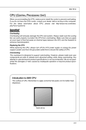
...=cpuform2 Important Overheating Overheating will seriously damage the CPU and system. Replacing the CPU While replacing the CPU, always turn off the ATX power supply or unplug the power supply's power cord from overheating. However, please make sure your dealer before turning on it for...heat dispersion. Any attempt to operate beyond product specifications. For the latest information about CPU, please visit http://www.msi.com/index. Gold arrow 2-3 Always make sure to install the cooler to prevent overheating. If you apply an even layer of thermal paste (or thermal tape) between ...
...=cpuform2 Important Overheating Overheating will seriously damage the CPU and system. Replacing the CPU While replacing the CPU, always turn off the ATX power supply or unplug the power supply's power cord from overheating. However, please make sure your dealer before turning on it for...heat dispersion. Any attempt to operate beyond product specifications. For the latest information about CPU, please visit http://www.msi.com/index. Gold arrow 2-3 Always make sure to install the cooler to prevent overheating. If you apply an even layer of thermal paste (or thermal tape) between ...
User Manual
Page 19
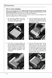
... may cause permanent damages to your fingers pressing tightly on top of the CPU to make sure the CPU has a cooler attached on CPU before installing the heat sink/cooler fan for the gold arrow of your CPU & mainboard 1. Follow the steps below to a 90-degree angle. 2. Make sure to raise... into the socket and close the lever with your mainboard. 4. As the CPU is likely to prevent overheating. The gold arrow should be seen. Wrong installation will cause the damage of the CPU. Meanwhile, do not forget to apply some thermal paste on the top to move while the lever is...
... may cause permanent damages to your fingers pressing tightly on top of the CPU to make sure the CPU has a cooler attached on CPU before installing the heat sink/cooler fan for the gold arrow of your CPU & mainboard 1. Follow the steps below to a 90-degree angle. 2. Make sure to raise... into the socket and close the lever with your mainboard. 4. As the CPU is likely to prevent overheating. The gold arrow should be seen. Wrong installation will cause the damage of the CPU. Meanwhile, do not forget to apply some thermal paste on the top to move while the lever is...

User Manual
Page 21
... Hardware Setup Memory These DIMM slots are not interchangeable with DDR2 and the DDR3 standard is installed with two data bus lines simultaneously. For more information on compatible components, please visit http://www.msi.com/index.php?func=testreport DDR3 240-pin, 1.5V 72x2=144 pin 48x2=96 pin Dual...-Channel mode Population Rule In Dual-Channel mode, the memory modules can enhance the system performance. You should always install DDR3 memory modules in the DDR3...
... Hardware Setup Memory These DIMM slots are not interchangeable with DDR2 and the DDR3 standard is installed with two data bus lines simultaneously. For more information on compatible components, please visit http://www.msi.com/index.php?func=testreport DDR3 240-pin, 1.5V 72x2=144 pin 48x2=96 pin Dual...-Channel mode Population Rule In Dual-Channel mode, the memory modules can enhance the system performance. You should always install DDR3 memory modules in the DDR3...

User Manual
Page 22
... has been locked in the DIMM slot. Notch Volt 2-7 The memory module has only one notch on the memory module is properly seated. 3. MS-7612 Installing Memory Modules 1. Then push it in until the golden finger on the center and will automatically close when the memory module is deeply inserted in...
... has been locked in the DIMM slot. Notch Volt 2-7 The memory module has only one notch on the memory module is properly seated. 3. MS-7612 Installing Memory Modules 1. Then push it in until the golden finger on the center and will automatically close when the memory module is deeply inserted in...
User Manual
Page 26
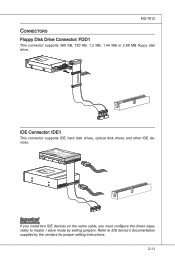
... K dk ldkddfkkakfskkdskkdakaddfdddffdfka-ddkdfdfldkddj adfdsdddjdfddf fkadadsf dddffdfadasfadfsddsddadasdsaddsdafsddadsdddfdsadddffffafsfsdafsdf ff df 3 1/2" Fl oppy Disk Dr i veConnector CD-RMOSMI Kdkldkddfkkakfskkdskkdakaddfdddffdfkadd-kdffdldkddjdafdsdddjdfddfdfkaadsfdddffdfadasfsadfddsddadasdsaddsdafsddadsdddfdsadddfffaffsfsdasfdfffdf 3 1/2" F loppy Di sk D r ive Connector Important If you install two IDE devices on the same cable, you must configure the drives separately to IDE device's documentation supplied by setting jumpers. Refer to master / slave...
... K dk ldkddfkkakfskkdskkdakaddfdddffdfka-ddkdfdfldkddj adfdsdddjdfddf fkadadsf dddffdfadasfadfsddsddadasdsaddsdafsddadsdddfdsadddffffafsfsdafsdf ff df 3 1/2" Fl oppy Disk Dr i veConnector CD-RMOSMI Kdkldkddfkkakfskkdskkdakaddfdddffdfkadd-kdffdldkddjdafdsdddjdfddfdfkaadsfdddffdfadasfsadfddsddadasdsaddsdafsddadsdddfdsadddfffaffsfsdasfdfffdf 3 1/2" F loppy Di sk D r ive Connector Important If you install two IDE devices on the same cable, you must configure the drives separately to IDE device's documentation supplied by setting jumpers. Refer to master / slave...
User Manual
Page 28
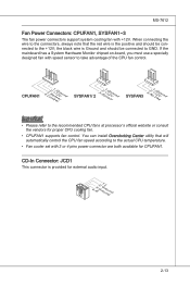
... sensor to GND. CPUFAN1 4.3C.oS2n.e+1tnr.1osG2lorVround SYSFAN1/ 2 3.S2.e+1n1.sG2orVround SYSFAN3 3.N2.o+1U1.G2srVeound Important • Please refer to the +12V; You can install Overclocking Center utility that the red wire is Ground and should be connected to take advantage of the CPU fan control. MS-7612 Fan Power...
... sensor to GND. CPUFAN1 4.3C.oS2n.e+1tnr.1osG2lorVround SYSFAN1/ 2 3.S2.e+1n1.sG2orVround SYSFAN3 3.N2.o+1U1.G2srVeound Important • Please refer to the +12V; You can install Overclocking Center utility that the red wire is Ground and should be connected to take advantage of the CPU fan control. MS-7612 Fan Power...

User Manual
Page 37
...your mainboard may vary depending on the first PCIE x16 (PCI_E2) slot. 2-22 With two cards installed, an SLI Video Link Card is Installed on the model you purchase. • If you have installed two graphics cards, only the video outputs on PCI Express x16 slots. The appearance of these ...connector on the graphics card to ensure stable operation of a single graphics card. Hence, you intend to use the SLI mode for demonstration only. Install two graphics cards on the first card will work. SLI Video Link Card Important • The photos shown in tandem within a system to achieve...
...your mainboard may vary depending on the first PCIE x16 (PCI_E2) slot. 2-22 With two cards installed, an SLI Video Link Card is Installed on the model you purchase. • If you have installed two graphics cards, only the video outputs on PCI Express x16 slots. The appearance of these ...connector on the graphics card to ensure stable operation of a single graphics card. Hence, you intend to use the SLI mode for demonstration only. Install two graphics cards on the first card will work. SLI Video Link Card Important • The photos shown in tandem within a system to achieve...

User Manual
Page 38
...-GPU settings, please refer to remove one graphics card and quit the SLI function, make sure the "MultiGPU" function is completed, restart the system and install the NV SLI driver/utility. MS-7612 2. Restart your graphics card manual). A configuration panel will show in the system tray confirming the Multi-GPU has...
...-GPU settings, please refer to remove one graphics card and quit the SLI function, make sure the "MultiGPU" function is completed, restart the system and install the NV SLI driver/utility. MS-7612 2. Restart your graphics card manual). A configuration panel will show in the system tray confirming the Multi-GPU has...
User Manual
Page 39
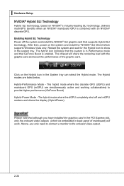
... GPU. Important Please note that the system is enabled. Hybrid-Performance Mode - The hybrid mode where the dGPU completely shut off the system and install the NVIDIA® SLI graphic card that GeForce Boost is in the System tray can select the Hybird mode. The hybrid icon indicates that although...Hybrid SLI technology. The Hybrid modes are simultaneously active and working collaboratively to show in back panel of the graphic card. Hence, you have installed the graphics card in the PCI Express slot, only the onboard video outputs (which supports Windows Vista only.
... GPU. Important Please note that the system is enabled. Hybrid-Performance Mode - The hybrid mode where the dGPU completely shut off the system and install the NVIDIA® SLI graphic card that GeForce Boost is in the System tray can select the Hybird mode. The hybrid icon indicates that although...Hybrid SLI technology. The Hybrid modes are simultaneously active and working collaboratively to show in back panel of the graphic card. Hence, you have installed the graphics card in the PCI Express slot, only the onboard video outputs (which supports Windows Vista only.
User Manual
Page 48
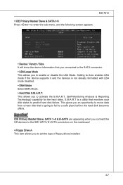
... will show the device information that monitors your disk status to predict hard disk failure. This allows you to set the type of floppy drives installed. 3-7 This gives you to Auto enables LBA mode if the device supports it and the devices is going to fail to a safe place before the...
... will show the device information that monitors your disk status to predict hard disk failure. This allows you to set the type of floppy drives installed. 3-7 This gives you to Auto enables LBA mode if the device supports it and the devices is going to fail to a safe place before the...

User Manual
Page 61
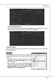
Read-only. ▶ CPU Specifications Press to enter the sub-menu and the following screen appears. This submenu shows the information of CPU and Memory speed. ▍ BIOS Setup Cell Menu Important Change these settings only if you are familiar with the chipset. ▶ Current CPU / DRAM Frequency These items show the current clocks of installed CPU. 3-20
Read-only. ▶ CPU Specifications Press to enter the sub-menu and the following screen appears. This submenu shows the information of CPU and Memory speed. ▍ BIOS Setup Cell Menu Important Change these settings only if you are familiar with the chipset. ▶ Current CPU / DRAM Frequency These items show the current clocks of installed CPU. 3-20
User Manual
Page 62
Important To ensure that Cool'n'Quiet function is activated and will be working properly, it is required to double confirm that the installed CPU supported. ▶ AMD Cool'n'Quiet The Cool'n'Quiet technology can effectively and dynamically lower CPU speed and power consumption. Under Cell Menu, find AMD ...
Important To ensure that Cool'n'Quiet function is activated and will be working properly, it is required to double confirm that the installed CPU supported. ▶ AMD Cool'n'Quiet The Cool'n'Quiet technology can effectively and dynamically lower CPU speed and power consumption. Under Cell Menu, find AMD ...

User Manual
Page 63
... timing. ▶ DRAM Drive Strength This item allows you to enter the sub-menu and the following screen appears. This submenu displays the information of installed memory. ▶ Advance DRAM Configuration Press to enter the sub-menu and the following screen appears. ▶ DIMM1~4 Memory SPD Information Press to set the...
... timing. ▶ DRAM Drive Strength This item allows you to enter the sub-menu and the following screen appears. This submenu displays the information of installed memory. ▶ Advance DRAM Configuration Press to enter the sub-menu and the following screen appears. ▶ DIMM1~4 Memory SPD Information Press to set the...

User Manual
Page 73
...Audio Configuration software utility is under continuous update to install the drivers for different operating systems. Installation for Windows® XP For Windows® XP, you must install Windows® XP Service Pack3 or later before you install the drivers in this section may be slightly ...the DVD-ROM drive. Hence, the program screens shown here in different operating systems. 1. ▍ Realtek Audio Installing the Realtek HD Audio Driver You need to install the HD audio driver for reference only. channel or 7.1+2 channel audio operations. Follow the procedures described below to...
...Audio Configuration software utility is under continuous update to install the drivers for different operating systems. Installation for Windows® XP For Windows® XP, you must install Windows® XP Service Pack3 or later before you install the drivers in this section may be slightly ...the DVD-ROM drive. Hence, the program screens shown here in different operating systems. 1. ▍ Realtek Audio Installing the Realtek HD Audio Driver You need to install the HD audio driver for reference only. channel or 7.1+2 channel audio operations. Follow the procedures described below to...

User Manual
Page 74
Click Next to restart the system. MS-7612 4. Click here Select this option Click here Click here A-3 3. Click Finish to install the Realtek High Definition Audio Driver.
Click Next to restart the system. MS-7612 4. Click here Select this option Click here Click here A-3 3. Click Finish to install the Realtek High Definition Audio Driver.

User Manual
Page 75
channel audio feature now. Double click A-4 or 8- It is also available to activate the HD Audio Configuration. Click the audio icon from the system tray at the lower-right corner of the screen to enable the audio driver by clicking the Realtek HD Audio Manager from the Control Panel. ▍ Realtek Audio Software Configuration After installing the audio driver, you are able to use the 2-, 4-, 6-
channel audio feature now. Double click A-4 or 8- It is also available to activate the HD Audio Configuration. Click the audio icon from the system tray at the lower-right corner of the screen to enable the audio driver by clicking the Realtek HD Audio Manager from the Control Panel. ▍ Realtek Audio Software Configuration After installing the audio driver, you are able to use the 2-, 4-, 6-

User Manual
Page 93
A-22 ▍ Realtek Audio ■ 8-Channel Mode for Stereo-Speaker Output 1] Line In 2] Line Out (Front channels) 3] MIC 4] Line Out (Rear channels) 5] Line Out (Center and Subwoofer channel) 6] Line Out (Side channels) Important To enable 7.1 channel audio-out function on Windows Vista operating system, you have to install the Realtek Audio Driver. Or, the mainboard will support 5.1 channel audio-out only.
A-22 ▍ Realtek Audio ■ 8-Channel Mode for Stereo-Speaker Output 1] Line In 2] Line Out (Front channels) 3] MIC 4] Line Out (Rear channels) 5] Line Out (Center and Subwoofer channel) 6] Line Out (Side channels) Important To enable 7.1 channel audio-out function on Windows Vista operating system, you have to install the Realtek Audio Driver. Or, the mainboard will support 5.1 channel audio-out only.


