User Guide
Page 10
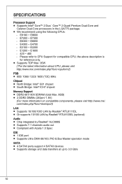
... DMA 66/100, PIO & Bus Master operation mode SATA ■ 4 SATAII ports support 4 SATAII devices ■ Supports storage and data transfers at up to CPU Support for reference only. ■ Supports TDP Max. 95W (*For the latest information about CPU, please visit http://www.msi.com/index.php?func=cpuform2) FSB ■ 800/ 1066/ 1333/ 1600 (*OC...
... DMA 66/100, PIO & Bus Master operation mode SATA ■ 4 SATAII ports support 4 SATAII devices ■ Supports storage and data transfers at up to CPU Support for reference only. ■ Supports TDP Max. 95W (*For the latest information about CPU, please visit http://www.msi.com/index.php?func=cpuform2) FSB ■ 800/ 1066/ 1333/ 1600 (*OC...
User Guide
Page 15
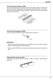
...operation of the mainboard. * Power supply of 350 watts (and above) is used to provide power to connect an ATX 24-pin power supply. Floppy Disk Drive Connector: FDD1 This connector supports 360 KB, 720 KB, 1.2 MB, 1.44 MB or 2.88 MB floppy disk drive. 15 Then push down the....2G6V1V.rP7o1.SuG81-n.rO9Gdo2.NurG0o2n#.ruR1do2n.eu+2ds2n5.+3dV2.5+4V5.GVround ATX 4-Pin Power Connector: JPWR2 This 12V power connector is highly recommended for system sta- MS-7529 ATX 24-Pin Power Connector: JPWR1 This connector allows you to the CPU. 2.G1.rGouronudnd 4.+31.+21V2V Important * Make sure that all...
...operation of the mainboard. * Power supply of 350 watts (and above) is used to provide power to connect an ATX 24-pin power supply. Floppy Disk Drive Connector: FDD1 This connector supports 360 KB, 720 KB, 1.2 MB, 1.44 MB or 2.88 MB floppy disk drive. 15 Then push down the....2G6V1V.rP7o1.SuG81-n.rO9Gdo2.NurG0o2n#.ruR1do2n.eu+2ds2n5.+3dV2.5+4V5.GVround ATX 4-Pin Power Connector: JPWR2 This 12V power connector is highly recommended for system sta- MS-7529 ATX 24-Pin Power Connector: JPWR1 This connector allows you to the CPU. 2.G1.rGouronudnd 4.+31.+21V2V Important * Make sure that all...
User Guide
Page 16
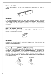
...When connecting the wire to the connectors, always note that the red wire is the positive and should be connected to take advantage of the CPU fan control. If the mainboard has a System Hardware Monitor chipset onboard, you must use a specially designed fan with +12V. Serial ATA Connector...is Ground and should be connected to one Serial ATA device. Otherwise, data loss may occur during transmission. IDE Connector: IDE1 This connector supports IDE hard disk drives, optical disk drives and other IDE devices. Important If you install two IDE devices on the same cable, you ...
...When connecting the wire to the connectors, always note that the red wire is the positive and should be connected to take advantage of the CPU fan control. If the mainboard has a System Hardware Monitor chipset onboard, you must use a specially designed fan with +12V. Serial ATA Connector...is Ground and should be connected to one Serial ATA device. Otherwise, data loss may occur during transmission. IDE Connector: IDE1 This connector supports IDE hard disk drives, optical disk drives and other IDE devices. Important If you install two IDE devices on the same cable, you ...
User Guide
Page 19
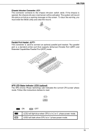
...you must enter the BIOS utility and clear the record. 1.C2.IGNTroRuUnd Parallel Port Header: JLPT1 This connector is a standard printer port that supports Enhanced Parallel Port (EPP) and Extended Capabilities Parallel Port (ECP) mode. 2.A4F.ED6R.#P8RI.1N#L0PI1T.TG2#_1r.GoS4u.1LrGon6INurd1.oGn#8ud...1P35NR1.DP7N41R.DP9N5R2.AD1NC26.DB3K2U7.#P5SE.YSLCT APS LED Status Indicator: LED2 (optional) The APS (Active Phase Switching) LED indicates the current CPU power phase mode. If the chassis is opened, the chassis intrusion mechanism will record this status and show a warning message on the ...
...you must enter the BIOS utility and clear the record. 1.C2.IGNTroRuUnd Parallel Port Header: JLPT1 This connector is a standard printer port that supports Enhanced Parallel Port (EPP) and Extended Capabilities Parallel Port (ECP) mode. 2.A4F.ED6R.#P8RI.1N#L0PI1T.TG2#_1r.GoS4u.1LrGon6INurd1.oGn#8ud...1P35NR1.DP7N41R.DP9N5R2.AD1NC26.DB3K2U7.#P5SE.YSLCT APS LED Status Indicator: LED2 (optional) The APS (Active Phase Switching) LED indicates the current CPU power phase mode. If the chassis is opened, the chassis intrusion mechanism will record this status and show a warning message on the ...
User Guide
Page 24
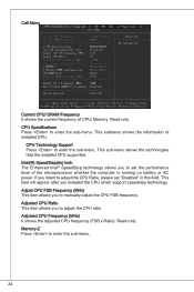
.... This field will appear after you to adjust the CPU ratio. Adjust CPU FSB Frequency (MHz) This item allows you installed the CPU which support speedstep technology. Adjusted CPU Frequency (MHz) It shows the adjusted CPU frequency (FSB x Ratio). This sub-menu shows the technologies that the installed CPU supported. Read-only. This submenu shows the information of...
.... This field will appear after you to adjust the CPU ratio. Adjust CPU FSB Frequency (MHz) This item allows you installed the CPU which support speedstep technology. Adjusted CPU Frequency (MHz) It shows the adjusted CPU frequency (FSB x Ratio). This sub-menu shows the technologies that the installed CPU supported. Read-only. This submenu shows the information of...


