User Guide
Page 11
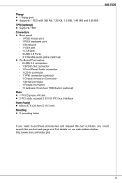
...Panel Audio connector ‑ 1 CD-In connector ‑ 1 TPM connector (optional) ‑ 1 Chassis Intrusion Connector ‑ 1 Serial connector ‑ 1 Parallel connector ‑ 1 Hardware Overclock FSB Switch (optional) Slots ■ 1 PCI Express x16 slot ■ 2 PCI slots, support 3.3V/ 5V PCI bus Interface Form Factor ■ Micro-ATX... (24.4cm X 19.3 cm) Mounting ■ 6 mounting holes If you need to purchase accessories and request the part numbers, you could search the product web page and find details on our web address below http://www.msi.com/index.php...
...Panel Audio connector ‑ 1 CD-In connector ‑ 1 TPM connector (optional) ‑ 1 Chassis Intrusion Connector ‑ 1 Serial connector ‑ 1 Parallel connector ‑ 1 Hardware Overclock FSB Switch (optional) Slots ■ 1 PCI Express x16 slot ■ 2 PCI slots, support 3.3V/ 5V PCI bus Interface Form Factor ■ Micro-ATX... (24.4cm X 19.3 cm) Mounting ■ 6 mounting holes If you need to purchase accessories and request the part numbers, you could search the product web page and find details on our web address below http://www.msi.com/index.php...
User Guide
Page 12
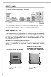
...Key Alignment Key Yellow triangle is the Pin 1 indicator 12 Yellow triangle is the Pin 1 indicator While doing the installation, be output from front panel if you purchase the mainboard with 3 audio jacks HARDWARE SETUP This chapter tells you how to install the CPU, memory modules, and expansion cards, ...as well as how to apply some thermal paste on connecting the peripheral devices, such as the mouse, keyboard, etc. REAR PANEL The rear panel provides the following connectors: PS/2 mouse LAN Line-In RS-Out Serial port VGA port Line-Out CS-Out PS/2 keyboard USB ports MIC...
...Key Alignment Key Yellow triangle is the Pin 1 indicator 12 Yellow triangle is the Pin 1 indicator While doing the installation, be output from front panel if you purchase the mainboard with 3 audio jacks HARDWARE SETUP This chapter tells you how to install the CPU, memory modules, and expansion cards, ...as well as how to apply some thermal paste on connecting the peripheral devices, such as the mouse, keyboard, etc. REAR PANEL The rear panel provides the following connectors: PS/2 mouse LAN Line-In RS-Out Serial port VGA port Line-Out CS-Out PS/2 keyboard USB ports MIC...
User Guide
Page 17
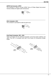
The JFP1 is provided for external audio input. 4.R3.G2.rG1o.urLonudnd Front Panel Connectors: JFP1, JFP2 These connectors are for electrical connection to the front panel switches and LEDs. PowPoewr LeEr DSwi2tc.h+41.0-6..N+8o.-Pin JFP1 1.+3.-5.-7.H+9D.RDReLseEesDrevteSdwitch SpeakeBr2uz.z-e4r.+6.-8.+ JFP2 1.G3.rSo5uu.Psn7opd.NweonedrPLLinEEDD 17 MS-7529 S/PDIF-Out ... & Philips Digital Interconnect Format) interface for digital audio transmission. 1.V2C.S3C.PGDrIoFund CD-In Connector: JCD1 This connector is compliant with Intel® Front Panel I/O Connectivity Design Guide.
The JFP1 is provided for external audio input. 4.R3.G2.rG1o.urLonudnd Front Panel Connectors: JFP1, JFP2 These connectors are for electrical connection to the front panel switches and LEDs. PowPoewr LeEr DSwi2tc.h+41.0-6..N+8o.-Pin JFP1 1.+3.-5.-7.H+9D.RDReLseEesDrevteSdwitch SpeakeBr2uz.z-e4r.+6.-8.+ JFP2 1.G3.rSo5uu.Psn7opd.NweonedrPLLinEEDD 17 MS-7529 S/PDIF-Out ... & Philips Digital Interconnect Format) interface for digital audio transmission. 1.V2C.S3C.PGDrIoFund CD-In Connector: JCD1 This connector is compliant with Intel® Front Panel I/O Connectivity Design Guide.
User Guide
Page 18
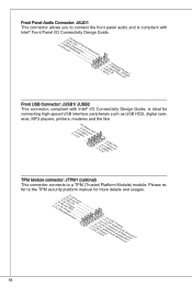
.... TPM Module connector: JTPM1 (optional) This connector connects to a TPM (Trusted Platform Module) module. Front Panel Audio Connector: JAUD1 This connector allows you to connect the front panel audio and is compliant with Intel® Front Panel I/O Connectivity Design Guide. 2.G4r.oP6uR.Mn8Ed.1INSC0Eo.DHNPeeCitnaeEdc#tPiohnone Detection 1.M3.IMC5.ILHC7e.RS9a.EdHNPeShaEodn_PeShERoNneDL Front...
.... TPM Module connector: JTPM1 (optional) This connector connects to a TPM (Trusted Platform Module) module. Front Panel Audio Connector: JAUD1 This connector allows you to connect the front panel audio and is compliant with Intel® Front Panel I/O Connectivity Design Guide. 2.G4r.oP6uR.Mn8Ed.1INSC0Eo.DHNPeeCitnaeEdc#tPiohnone Detection 1.M3.IMC5.ILHC7e.RS9a.EdHNPeShaEodn_PeShERoNneDL Front...

User Guide
Page 89
PowPoewr LeEr DSwi2tc.h+41.0-6..N+8o.-Pin JFP1 1.+3.-5.-7.H+9D.RDReLseEesDrevteSdwitch SpeakeBr2uz.z-e4r.+6.-8.+ JFP2 1.G3.rSo5uu.Psn7opd.NweonedrPLLinEEDD 89 MS-7529 S/PDIF-Out: JSPD1 S/PDIF (Sony & Philips Digital Interconnect Format 1.V2C.S3C.PGDrIoFund CD-In: JCD1 4.R3.G2.rG1o.urLonudnd JFP1, JFP2 JFP1 Intel® Front Panel I/O Connectivity Design Guide.
PowPoewr LeEr DSwi2tc.h+41.0-6..N+8o.-Pin JFP1 1.+3.-5.-7.H+9D.RDReLseEesDrevteSdwitch SpeakeBr2uz.z-e4r.+6.-8.+ JFP2 1.G3.rSo5uu.Psn7opd.NweonedrPLLinEEDD 89 MS-7529 S/PDIF-Out: JSPD1 S/PDIF (Sony & Philips Digital Interconnect Format 1.V2C.S3C.PGDrIoFund CD-In: JCD1 4.R3.G2.rG1o.urLonudnd JFP1, JFP2 JFP1 Intel® Front Panel I/O Connectivity Design Guide.

