User Guide
Page 10
the above description is for compatible CPU; SPECIFICATIONS Processor Support ■ Supports Intel® Core™ 2 Duo/ Core™ 2 Quad/ Pentium Dual-Core and ... SATAII ports support 4 SATAII devices ■ Supports storage and data transfers at up to CPU Support for reference only. ■ Supports TDP Max. 95W (*For the latest information about CPU, please visit http://www.msi.com/index.php?func=cpuform2) FSB ■ 800/ 1066/ 1333/ 1600 (*OC) ...(total Max. 8GB) ■ 2 DDR2 DIMMs (240pin/ 1.8V) (For more information on compatible components, please visit http://www.msi.
the above description is for compatible CPU; SPECIFICATIONS Processor Support ■ Supports Intel® Core™ 2 Duo/ Core™ 2 Quad/ Pentium Dual-Core and ... SATAII ports support 4 SATAII devices ■ Supports storage and data transfers at up to CPU Support for reference only. ■ Supports TDP Max. 95W (*For the latest information about CPU, please visit http://www.msi.com/index.php?func=cpuform2) FSB ■ 800/ 1066/ 1333/ 1600 (*OC) ...(total Max. 8GB) ■ 2 DDR2 DIMMs (240pin/ 1.8V) (For more information on compatible components, please visit http://www.msi.
User Guide
Page 12
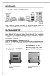
... modules, and expansion cards, as well as how to setup the jumpers on it for LGA775 When you do not have the CPU cooler, consult your dealer before turning on connecting the peripheral devices, such as the mouse, keyboard, etc. Remember to prevent overheating. Alignment Key ...Alignment Key Yellow triangle is the Pin 1 indicator 12 Yellow triangle is the Pin 1 indicator CPU & Cooler Installation Procedures for better heat dispersion. The surface of LGA 775 CPU. If you are installing the CPU, make sure to install the cooler to apply some thermal paste on the mainboard. The pin...
... modules, and expansion cards, as well as how to setup the jumpers on it for LGA775 When you do not have the CPU cooler, consult your dealer before turning on connecting the peripheral devices, such as the mouse, keyboard, etc. Remember to prevent overheating. Alignment Key ...Alignment Key Yellow triangle is the Pin 1 indicator 12 Yellow triangle is the Pin 1 indicator CPU & Cooler Installation Procedures for better heat dispersion. The surface of LGA 775 CPU. If you are installing the CPU, make sure to install the cooler to apply some thermal paste on the mainboard. The pin...
User Guide
Page 13
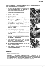
... the four hooks down the load lever lightly onto the load plate, and then secure the lever with the heatsink. Finally, attach the CPU Fan cable to the CPU fan connector on it ) to protect the socket pin. 2. Mainboard photos shown in the socket housing frame. Lift the load lever up and.... Wrong installation will cause the damage of socket reveal. 4. MS-7529 Follow the steps below to confirm that the alignment keys are matched. 7. The CPU socket has a plastic cap on the mainboard. Open the load lever. 5. Be sure to grasp on it to fasten the cooler. If not, take out ...
... the four hooks down the load lever lightly onto the load plate, and then secure the lever with the heatsink. Finally, attach the CPU Fan cable to the CPU fan connector on it ) to protect the socket pin. 2. Mainboard photos shown in the socket housing frame. Lift the load lever up and.... Wrong installation will cause the damage of socket reveal. 4. MS-7529 Follow the steps below to confirm that the alignment keys are matched. 7. The CPU socket has a plastic cap on the mainboard. Open the load lever. 5. Be sure to grasp on it to fasten the cooler. If not, take out ...
User Guide
Page 15
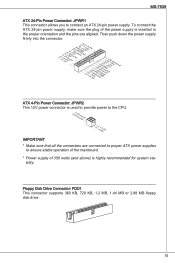
...: JPWR1 This connector allows you to ensure stable operation of the mainboard. * Power supply of the power supply is used to provide power to the CPU. 2.G1.rGouronudnd 4.+31.+21V2V Important * Make sure that all the connectors are aligned. Then push down the power supply firmly into the connector. 1.+23....5uG6Vn.r7+do.5uG8Vn.rP9do.Wu51nV0R1d.S1+O1B.1+K2211.V+3213.V+4.133.-5V.113.2G6V1V.rP7o1.SuG81-n.rO9Gdo2.NurG0o2n#.ruR1do2n.eu+2ds2n5.+3dV2.5+4V5.GVround ATX 4-Pin Power Connector: JPWR2 This 12V power connector is inserted in the proper orientation and the pins are connected to proper...
...: JPWR1 This connector allows you to ensure stable operation of the mainboard. * Power supply of the power supply is used to provide power to the CPU. 2.G1.rGouronudnd 4.+31.+21V2V Important * Make sure that all the connectors are aligned. Then push down the power supply firmly into the connector. 1.+23....5uG6Vn.r7+do.5uG8Vn.rP9do.Wu51nV0R1d.S1+O1B.1+K2211.V+3213.V+4.133.-5V.113.2G6V1V.rP7o1.SuG81-n.rO9Gdo2.NurG0o2n#.ruR1do2n.eu+2ds2n5.+3dV2.5+4V5.GVround ATX 4-Pin Power Connector: JPWR2 This 12V power connector is inserted in the proper orientation and the pins are connected to proper...
User Guide
Page 16
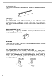
... the mainboard has a System Hardware Monitor chipset onboard, you must use a specially designed fan with +12V. Each connector can connect to take advantage of the CPU fan control. Serial ATA Connector: SATA1 ~ 4 This connector is Ground and should be connected to master / slave mode by the vendors for jumper setting instructions...
... the mainboard has a System Hardware Monitor chipset onboard, you must use a specially designed fan with +12V. Each connector can connect to take advantage of the CPU fan control. Serial ATA Connector: SATA1 ~ 4 This connector is Ground and should be connected to master / slave mode by the vendors for jumper setting instructions...
User Guide
Page 19
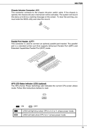
... Status Indicator: LED2 (optional) The APS (Active Phase Switching) LED indicates the current CPU power phase mode. LED2 : ON : OFF LED2 will dark when CPU is used to connect an optional parallel port bracket. LED2 will light blue when CPU is in 1 phase power mode. 19 MS-7529 Chassis Intrusion Connector: JCI1 This...
... Status Indicator: LED2 (optional) The APS (Active Phase Switching) LED indicates the current CPU power phase mode. LED2 : ON : OFF LED2 will dark when CPU is used to connect an optional parallel port bracket. LED2 will light blue when CPU is in 1 phase power mode. 19 MS-7529 Chassis Intrusion Connector: JCI1 This...
User Guide
Page 22
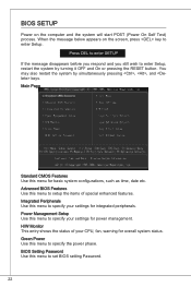
... POST (Power On Self Test) process. BIOS Setup Power on the screen, press key to enter Setup. Green Power Use this menu to specify your CPU, fan, warning for integrated peripherals. H/W Monitor This entry shows the status of special enhanced features. Advanced BIOS Features Use this menu to set BIOS setting...
... POST (Power On Self Test) process. BIOS Setup Power on the screen, press key to enter Setup. Green Power Use this menu to specify your CPU, fan, warning for integrated peripherals. H/W Monitor This entry shows the status of special enhanced features. Advanced BIOS Features Use this menu to set BIOS setting...
User Guide
Page 24
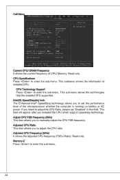
... microprocessor whether the computer is running on battery or AC power. Adjusted CPU Ratio This item allows you to adjust the CPU ratio. CPU Technology Support Press to enter the sub-menu. 24 CPU Specifications Press to set "Disabled" in this field. This submenu shows ...Intel® SpeedStep technology allows you installed the CPU which support speedstep technology. Cell Menu Current CPU/ DRAM Frequency It shows the current frequency of installed CPU. This sub-menu shows the technologies that the installed CPU supported. Adjust CPU FSB Frequency (MHz) This item allows you ...
... microprocessor whether the computer is running on battery or AC power. Adjusted CPU Ratio This item allows you to adjust the CPU ratio. CPU Technology Support Press to enter the sub-menu. 24 CPU Specifications Press to set "Disabled" in this field. This submenu shows ...Intel® SpeedStep technology allows you installed the CPU which support speedstep technology. Cell Menu Current CPU/ DRAM Frequency It shows the current frequency of installed CPU. This sub-menu shows the technologies that the installed CPU supported. Adjust CPU FSB Frequency (MHz) This item allows you ...
User Guide
Page 40
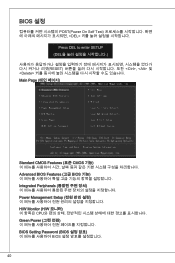
BIOS 설정 POST(Power On Self Test DEL Press DEL to enter SETUP (DEL RESET Ctrl>, 및
BIOS 설정 POST(Power On Self Test DEL Press DEL to enter SETUP (DEL RESET Ctrl>, 및
User Guide
Page 102
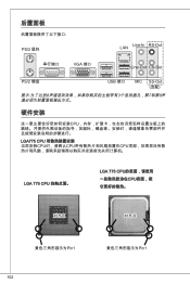
后置面板 PS/2 鼠标 LAN Line-In RS-Out 串行端口 VGA 端口 Line-Out CS-Out PS/2 键盘 USB 端口 MIC SS-Out (选配) 8 3 7和第8 硬件安装 CPU LGA775 CPU CPU CPU CPU LGA 775 CPU LGA 775 CPU CPU 对齐点 对齐点 Pin1 102 Pin1
后置面板 PS/2 鼠标 LAN Line-In RS-Out 串行端口 VGA 端口 Line-Out CS-Out PS/2 键盘 USB 端口 MIC SS-Out (选配) 8 3 7和第8 硬件安装 CPU LGA775 CPU CPU CPU CPU LGA 775 CPU LGA 775 CPU CPU 对齐点 对齐点 Pin1 102 Pin1
User Guide
Page 138
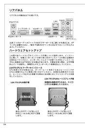
PS/2マウス LAN Line-In RS-Out VGAポート Line-Out CS-Out PS/2 USBポート MIC SS-Out 8 7番目や8 LGA775 CPU CPU CPU CPU LGA 775 CPU LGA 775 CPUの端子側 1 1 138
PS/2マウス LAN Line-In RS-Out VGAポート Line-Out CS-Out PS/2 USBポート MIC SS-Out 8 7番目や8 LGA775 CPU CPU CPU CPU LGA 775 CPU LGA 775 CPUの端子側 1 1 138
User Guide
Page 148
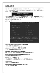
BIOSの設定 POST (Power On Self Test DEL Press DEL to enter SETUP (とと
BIOSの設定 POST (Power On Self Test DEL Press DEL to enter SETUP (とと


