User Guide
Page 19
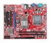
.... LED2 will be activated. The system will light blue when CPU is in 1 phase power mode. 19 If the chassis is used to connect an optional parallel port bracket. To clear the warning, you must enter the BIOS utility and ....SudPr.5TNonR.BuPdo7Nn#R.PDdP9NiRn0.DP1N1R1D1.NP32DR.1P35NR1.DP7N41R.DP9N5R2.AD1NC26.DB3K2U7.#P5SE.YSLCT APS LED Status Indicator: LED2 (optional) The APS (Active Phase Switching) LED indicates the current CPU power phase mode. LED2 : ON : OFF LED2 will record this status and show a warning message on the screen. Follow tthe instructions belows to...
.... LED2 will be activated. The system will light blue when CPU is in 1 phase power mode. 19 If the chassis is used to connect an optional parallel port bracket. To clear the warning, you must enter the BIOS utility and ....SudPr.5TNonR.BuPdo7Nn#R.PDdP9NiRn0.DP1N1R1D1.NP32DR.1P35NR1.DP7N41R.DP9N5R2.AD1NC26.DB3K2U7.#P5SE.YSLCT APS LED Status Indicator: LED2 (optional) The APS (Active Phase Switching) LED indicates the current CPU power phase mode. LED2 : ON : OFF LED2 will record this status and show a warning message on the screen. Follow tthe instructions belows to...
User Guide
Page 20
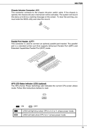
... configuration, set the jumper to clear data. 1 JBAT1 1 Keep Data 1 Clear Data Important You can clear CMOS by changing this switch. If you power off . Hardware Overclock FSB Switch: OC_SW1 (optional) You can overclock the FSB to 1-2 pin position. Clear CMOS Jumper: JBAT1 There is not guaranteed. * When ... -> 266 MHz 200 -> 333 MHz 266 -> 333 MHz 200 -> 400 MHz 266 -> 400 MHz 333 -> 400 MHz Important * Make sure that has a power supply from an external battery to default. Avoid clearing the CMOS while the system is turned on ; With the CMOS RAM, the system can automatically...
... configuration, set the jumper to clear data. 1 JBAT1 1 Keep Data 1 Clear Data Important You can clear CMOS by changing this switch. If you power off . Hardware Overclock FSB Switch: OC_SW1 (optional) You can overclock the FSB to 1-2 pin position. Clear CMOS Jumper: JBAT1 There is not guaranteed. * When ... -> 266 MHz 200 -> 333 MHz 266 -> 333 MHz 200 -> 400 MHz 266 -> 400 MHz 333 -> 400 MHz Important * Make sure that has a power supply from an external battery to default. Avoid clearing the CMOS while the system is turned on ; With the CMOS RAM, the system can automatically...
User Guide
Page 21
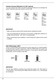
... C# INT D# 4 INT D# INT A# 21 The PCI IRQ pins are hardware lines over which devices can send interrupt signals to the PCI bus pins as jumpers, switches or BIOS configuration. The PCI Express x16 slot PCI Slot The PCI slot supports LAN card, SCSI card, USB card, and other add-on cards... that you unplug the power supply first. MS-7529 PCI Express Slot The PCI Express slot supports the PCI Express interface expansion card. PCI Interrupt Request Routing When adding or...
... C# INT D# 4 INT D# INT A# 21 The PCI IRQ pins are hardware lines over which devices can send interrupt signals to the PCI bus pins as jumpers, switches or BIOS configuration. The PCI Express x16 slot PCI Slot The PCI slot supports LAN card, SCSI card, USB card, and other add-on cards... that you unplug the power supply first. MS-7529 PCI Express Slot The PCI Express slot supports the PCI Express interface expansion card. PCI Interrupt Request Routing When adding or...


