Setup Sheet
Page 2
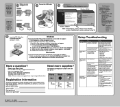
...number Date purchased Store where purchased • 31 (Photo) • 32 (Black) • 34 (Black) • 33 (Color) • 35 (Color) Setup Troubleshooting Symptom Diagnosis Solution Power light is not lit" symptom at 1-800-332-4120. Disconnect the power cord from the wall ...power cord pushed all the way into the wall outlet. All rights reserved. Note: After installation is on your desktop, double-click the Lexmark 3300 Series Installer icon. 2 Double-click Install, and follow the instructions on all open programs. 2 Temporarily disable any other electrical devices ...
...number Date purchased Store where purchased • 31 (Photo) • 32 (Black) • 34 (Black) • 33 (Color) • 35 (Color) Setup Troubleshooting Symptom Diagnosis Solution Power light is not lit" symptom at 1-800-332-4120. Disconnect the power cord from the wall ...power cord pushed all the way into the wall outlet. All rights reserved. Note: After installation is on your desktop, double-click the Lexmark 3300 Series Installer icon. 2 Double-click Install, and follow the instructions on all open programs. 2 Temporarily disable any other electrical devices ...

Service Manual
Page 11
... used to isolate failing field replaceable units (FRUs). 3. Preface 4479-XXX This manual contains maintenance procedures for making All-In-One adjustments and removing and installing FRUs. 5. CAUTION: A caution identifies something that could damage the product hardware or software. Diagnostic aids contains tests and checks used to locate or repeat symptoms...
... used to isolate failing field replaceable units (FRUs). 3. Preface 4479-XXX This manual contains maintenance procedures for making All-In-One adjustments and removing and installing FRUs. 5. CAUTION: A caution identifies something that could damage the product hardware or software. Diagnostic aids contains tests and checks used to locate or repeat symptoms...
Service Manual
Page 13
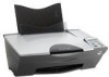
General information 4479-XXX The Lexmark™ 3300 Series (4479-XXX) All-In-One features an electromechanical color scanner, copier, and printer that creates characters and graphics by composing programmed patterns of 480 nozzles installs on the left . The printhead assembly and ink supply are ... printer. The photo cartridge has a total of inkjets or nozzles in two directions from either cartridge. Dual printheads provide color and true black printing without changing printheads. The number and size of 480 nozzles and installs on the right. The black print cartridge has...
General information 4479-XXX The Lexmark™ 3300 Series (4479-XXX) All-In-One features an electromechanical color scanner, copier, and printer that creates characters and graphics by composing programmed patterns of 480 nozzles installs on the left . The printhead assembly and ink supply are ... printer. The photo cartridge has a total of inkjets or nozzles in two directions from either cartridge. Dual printheads provide color and true black printing without changing printheads. The number and size of 480 nozzles and installs on the right. The black print cartridge has...
Service Manual
Page 26
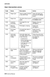
Short test detected short-circuit in the correct slots. Printhead ID is an incorrect home position. Install the print cartridges in printhead. Automatic alignment has failed. May be due to the following: • A bad sensor • Performed alignment on reused paper • ... Print Carrier Stall Print Incomplete Printhead Short Printhead Programming Description Action There is missing. and press the Arrow button. This error is out of printheads Install print cartridge(s).
Short test detected short-circuit in the correct slots. Printhead ID is an incorrect home position. Install the print cartridges in printhead. Automatic alignment has failed. May be due to the following: • A bad sensor • Performed alignment on reused paper • ... Print Carrier Stall Print Incomplete Printhead Short Printhead Programming Description Action There is missing. and press the Arrow button. This error is out of printheads Install print cartridge(s).

Service Manual
Page 31
If the encoder strip is not installed correctly, it can be caused by: • A broken circuit or short-circuit in the motor • A bind in the carrier transport mechanism Disconnect the carrier ... frame. If voltage is damaged, replace it is free of the carrier transport motor. A noisy or chattering motor or a motor that the encoder strip is installed correctly and is connected, check for approximately 29 V dc on pins 1 and 2 or at the wire connections located on the rear of grease or dirt...
If the encoder strip is not installed correctly, it can be caused by: • A broken circuit or short-circuit in the motor • A bind in the carrier transport mechanism Disconnect the carrier ... frame. If voltage is damaged, replace it is free of the carrier transport motor. A noisy or chattering motor or a motor that the encoder strip is installed correctly and is connected, check for approximately 29 V dc on pins 1 and 2 or at the wire connections located on the rear of grease or dirt...
Service Manual
Page 32
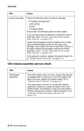
... of the printhead carrier for wear or damage: • Printhead cartridge latch • Latch spring • Carrier • Printhead cables Ensure that the belt is installed and is not binding. If the gold contacts are defective, replace the carrier assembly. Check the gold-plated contacts located on as the CIS module...
... of the printhead carrier for wear or damage: • Printhead cartridge latch • Latch spring • Carrier • Printhead cables Ensure that the belt is installed and is not binding. If the gold contacts are defective, replace the carrier assembly. Check the gold-plated contacts located on as the CIS module...
Service Manual
Page 37
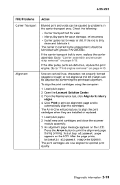
If the rod is worn, replace the carrier assembly. To align the print cartridges using the computer: 1. Open the Lexmark Solution Center. 3. Click Print to print an alignment page and to fix blurry edges. 4. If the carrier transport belt is dirty, clean and ... Action Blurred print and voids can be caused by performing the printhead alignment. Go to "Carrier assembly and encoder strip removal" on the LCD. Install new print cartridges and close the scanner module assembly. 3. Go to "Print engine removal" on the LCD. An alignment page message appears on page...
If the rod is worn, replace the carrier assembly. To align the print cartridges using the computer: 1. Open the Lexmark Solution Center. 3. Click Print to print an alignment page and to fix blurry edges. 4. If the carrier transport belt is dirty, clean and ... Action Blurred print and voids can be caused by performing the printhead alignment. Go to "Carrier assembly and encoder strip removal" on the LCD. Install new print cartridges and close the scanner module assembly. 3. Go to "Print engine removal" on the LCD. An alignment page message appears on page...

Service Manual
Page 39
... paper in good condition. The single test page consists of the carrier and a good color cartridge in the right. 4. To run a complete test page of black and color patterns, be sure the print cartridges are in the paper support. 6. Install a good black print cartridge in the left side of the following information: •...
... paper in good condition. The single test page consists of the carrier and a good color cartridge in the right. 4. To run a complete test page of black and color patterns, be sure the print cartridges are in the paper support. 6. Install a good black print cartridge in the left side of the following information: •...

Service Manual
Page 43
... risk of static electricity from your body to prevent an increase of damage because they make adjustments to the All-In-One and how to install the part into its pins. if you need to make a discharge path from clothing fibers, carpets, and furniture. • Put the ESD wrist...XXX This chapter explains how to put it into the machine. • Make as few movements as turning off power before handling electronic parts. Install machine covers when you are not working with your body through the ESD-sensitive part. (Large metal objects can be sensitive to the system ...
... risk of static electricity from your body to prevent an increase of damage because they make adjustments to the All-In-One and how to install the part into its pins. if you need to make a discharge path from clothing fibers, carpets, and furniture. • Put the ESD wrist...XXX This chapter explains how to put it into the machine. • Make as few movements as turning off power before handling electronic parts. Install machine covers when you are not working with your body through the ESD-sensitive part. (Large metal objects can be sensitive to the system ...

Service Manual
Page 44
... alignment complete appears. release them carefully. Press the Arrow button to which it is latched. 4-2 Service Manual The latches break easily; Install new print cartridges and close the scanner module assembly. 3. During printing, Printing alignment page appears on the LCD. To remove such parts...the part to print the alignment page. CAUTION: Unplug the power cord before removing any parts. Removal procedures The following procedures are installed or replaced. 1. Load plain paper. 2. 4479-XXX Adjustments The All-In-One will prompt you to align the print cartridges ...
... alignment complete appears. release them carefully. Press the Arrow button to which it is latched. 4-2 Service Manual The latches break easily; Install new print cartridges and close the scanner module assembly. 3. During printing, Printing alignment page appears on the LCD. To remove such parts...the part to print the alignment page. CAUTION: Unplug the power cord before removing any parts. Removal procedures The following procedures are installed or replaced. 1. Load plain paper. 2. 4479-XXX Adjustments The All-In-One will prompt you to align the print cartridges ...

Service Manual
Page 57
Note: When installing an encoder strip, make sure that the arrow on right end is pointing down. Disconnect the flat printhead cables and clip (A). 4479-XXX 4. Repair information 4-15 Remove the encoder strip. Carrier assembly and encoder strip removal 1. Disconnect both ends (B) of the encoder strip. 5. Remove the print engine. 3. Remove the scanner module assembly. 2.
Note: When installing an encoder strip, make sure that the arrow on right end is pointing down. Disconnect the flat printhead cables and clip (A). 4479-XXX 4. Repair information 4-15 Remove the encoder strip. Carrier assembly and encoder strip removal 1. Disconnect both ends (B) of the encoder strip. 5. Remove the print engine. 3. Remove the scanner module assembly. 2.


