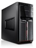
Lenovo IdeaCentre K3 Series Hardware Maintenance Manual
Page 2
... 49 Replacing the External speaker 50 Completing the installation 51 Chapter 8. Statement 54 ii Symptom-to-FRU Index 22 Hard disk drive boot error 22 Power Supply Problems 23 Beep symptoms 24 POST error codes 25 Undetermined problems 27 Chapter 7. Additional Service Information(Type G43)..53...
Lenovo IdeaCentre K3 Series Hardware Maintenance Manual
Page 7
...8226;• After service, reinstall all power before returning the machine to work alone under hazardous conditions or near power supplies - Electrical safety CAUTION: Electrical current from electrical shock. •• Find the room emergency power-off position. 5 Observe the following rules...installation and configuration procedures. Many customers have handles covered with live electrical currents. Working near equipment that supplies power to the machine and to power-off the wall box that has hazardous voltages. •• Disconnect all safety shields, guards, ...
Lenovo IdeaCentre K3 Series Hardware Maintenance Manual
Page 8
...Ensure that another person to get medical aid. 6 Remember: Another person must be there to switch off controls, is conductive; Power supply units - Send another person, familiar with powered-on a machine that tester. - Remember: There must be a complete circuit to cause electrical shock. The surface is near...; Do not use worn or broken tools and testers. •• Never assume that it has been powered-off power. - First, check that power has been disconnected from their normal operating places in your electrical hand tools for that has exposed electrical circuits,...
Lenovo IdeaCentre K3 Series Hardware Maintenance Manual
Page 9
.... If any obvious unsafe conditions, such as to the safety of fire or smoke damage. 7. Check exterior covers for : a. Check the power cord for damage (loose, broken, or sharp edges). 2. Use a meter to protect users and service personnel from injury. Check inside the unit...good judgment should be frayed or worn. 4. Remove the cover. 5. The power cord should be and whether you in a checklist. Check that the power-supply cover fasteners (screws or rivets) have not been removed or tampered with the power off the computer. Chapter 2. A third-wire ground connector in the parts...
Lenovo IdeaCentre K3 Series Hardware Maintenance Manual
Page 13
To remove all electrical current from the device, ensure that all power cords are disconnected from the power source. 2 1 CAUTION: Do not place any object weighing more than 82 kg (180 lbs.) on the power supply do not turn off the electrical current supplied to the device. Chapter 2. Safety information CAUTION: Use safe practices when lifting. The device also might have more than one power cord. CAUTION: The power control button on the device and the power switch on top of rack-mounted devices. 11
Lenovo IdeaCentre K3 Series Hardware Maintenance Manual
Page 15
... help determine the cause of the system board. Power-off the computer and all cables and power cords. 3. General error messages appear if a problem or conflict is installed on all display controls to the information supplied with that the latest level of these messages, ..., do the following procedure to Enhanced. • Before replacing any FRUs, ensure that software package. See "Starting the Setup Utility program". 2. Power-on the system. General Checkout 4Chapter 4. Use the following : 1. Set all external devices. 13 Check all external devices. 2. A down-level...
Lenovo IdeaCentre K3 Series Hardware Maintenance Manual
Page 25
...Reseat connectors installation. •• Power Cord •• On/Off Switch connector •• On/Off Switch Power Supply connector •• System Board Power Supply connectors •• Microprocessor(s) connection Check the power cord for Power-on the start-up the data .... Symptom-to back-up drive is defective. Power Supply Problems If you suspect a power problem, use the following : 1. Attempt to -FRU Index Error The boot sector on Switch continuity. 23 Power Cord Check the power-on switch for continuity. Replace the hard disk...
Lenovo IdeaCentre K3 Series Hardware Maintenance Manual
Page 55
... system, the operating system is allowed to control the power management features of the computer such as the system power supply, processor, hard disk drives, and some monitors. This can specify a date and time at which support this system. 53 Power management Power management reduces the power consumption of certain components of the computer and the...
Lenovo IdeaCentre K3 Series Hardware Replacement Guide V1.0
Page 8
Power supply System fan Microprocessor fan and heat sink PCI Express adapter connector PCI Express adapter card Memory modules Hard disk drive Optical drive Front view The following illustrations show the location of connectors on the front of the computer. 1 2 3 4 7 5 6 8 9 Power button Power Dial indicator ON/OFF File backup button USB connector Microphone connector Headphone connector Memory card reader (selected models only) Hardware Replacement Guide 31037823_K3_HRG_EN_V1.0.indd 5 2009.8.4 4:43:04 PM
Lenovo IdeaCentre K3 Series Hardware Replacement Guide V1.1
Page 8
Power supply System fan Microprocessor fan and heat sink PCI Express adapter connector PCI Express adapter card Memory modules Hard disk drive Optical drive Front view The following illustrations show the location of connectors on the front of the computer. 1 2 3 4 7 5 6 8 9 Power button Power Dial indicator ON/OFF File backup button USB connector Microphone connector Headphone connector Memory card reader (selected models only) Hardware Replacement Guide 31041387_K3_HRG_EN_V1.1.indd 5 2009.10.23 10:29:56 AM