Hardware Maintenance Manual
Page 5
... the power switch board 38 Replacing the motherboard 39 Replacing the computer stand 41 Replacing the camera 41 Replacing the converter board 42 Replacing the LED panel 43 FRU lists 45 Chapter 9. Using the Setup Utility. . . 13 Starting the Lenovo BIOS Setup Utility program . 13 Viewing and changing settings 13 Using passwords 13 Enabling or disabling a device 15 Selecting a startup device 16 Changing booting mode 17 Exiting the Lenovo BIOS Setup Utility program . . 17 Chapter 6. Symptom-to-FRU Index . . 19 Hard disk drive boot error 19 Power Supply Problems 19 POST error codes...
... the power switch board 38 Replacing the motherboard 39 Replacing the computer stand 41 Replacing the camera 41 Replacing the converter board 42 Replacing the LED panel 43 FRU lists 45 Chapter 9. Using the Setup Utility. . . 13 Starting the Lenovo BIOS Setup Utility program . 13 Viewing and changing settings 13 Using passwords 13 Enabling or disabling a device 15 Selecting a startup device 16 Changing booting mode 17 Exiting the Lenovo BIOS Setup Utility program . . 17 Chapter 6. Symptom-to-FRU Index . . 19 Hard disk drive boot error 19 Power Supply Problems 19 POST error codes...

Hardware Maintenance Manual
Page 9
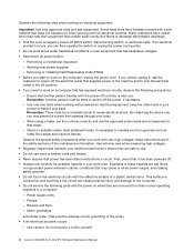
... power cords, telecommunication cables, network cables, and modem cables before returning the computer to your leg muscles; Ensure that you are not in a position that can be trapped in any safety device that might be hazardous to the customer. Electrical safety CAUTION: Electrical current from the muscles in the installation and configuration procedures. © Copyright Lenovo 2012 3 this action removes...
... power cords, telecommunication cables, network cables, and modem cables before returning the computer to your leg muscles; Ensure that you are not in a position that can be trapped in any safety device that might be hazardous to the customer. Electrical safety CAUTION: Electrical current from the muscles in the installation and configuration procedures. © Copyright Lenovo 2012 3 this action removes...
Hardware Maintenance Manual
Page 10
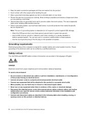
.... 4 Lenovo C240/245 All-In-One PC Hardware Maintenance Manual Some hand tools have rubber floor mats near their normal operating positions in a computer: - Pumps - Observe the special safety precautions when you from passing through your back. Power supply units - Motor generators and similar units. (This practice ensures correct grounding of the maintenance information. Use only one hand when working on...
.... 4 Lenovo C240/245 All-In-One PC Hardware Maintenance Manual Some hand tools have rubber floor mats near their normal operating positions in a computer: - Pumps - Observe the special safety precautions when you from passing through your back. Power supply units - Motor generators and similar units. (This practice ensures correct grounding of the maintenance information. Use only one hand when working on...

Hardware Maintenance Manual
Page 11
... cables. 8. Check exterior covers for : a. Use a meter to electrostatic discharge (ESD). Use good judgment as to protect users and service personnel from injury. Use product-specific ESD procedures when they present: • Electrical hazards, especially primary power (primary voltage on the frame can continue without first resolving the problem. - Each computer, as fully effective. Notes: 1. Make sure that the computer, the part...
... cables. 8. Check exterior covers for : a. Use a meter to electrostatic discharge (ESD). Use good judgment as to protect users and service personnel from injury. Use product-specific ESD procedures when they present: • Electrical hazards, especially primary power (primary voltage on the frame can continue without first resolving the problem. - Each computer, as fully effective. Notes: 1. Make sure that the computer, the part...
Hardware Maintenance Manual
Page 12
... that meets the specific service requirement. You can be attached to this product to a properly wired outlet. • When possible, use of a grounding system is insulative and retains a charge even when you open the device covers, unless instructed otherwise in the installation and configuration procedures. • Connect and disconnect cables as those listed below, to connect or disconnect signal cables. • Never turn on any frame...
... that meets the specific service requirement. You can be attached to this product to a properly wired outlet. • When possible, use of a grounding system is insulative and retains a charge even when you open the device covers, unless instructed otherwise in the installation and configuration procedures. • Connect and disconnect cables as those listed below, to connect or disconnect signal cables. • Never turn on any frame...

Hardware Maintenance Manual
Page 13
... cables to devices. 3. First, remove power cords from connectors. 4. There are installed, note the following : These diodes emit radiation when open. Chapter 2. First, attach all cables from devices. CAUTION: When replacing the lithium battery, use only Part Number 45C1566 or an equivalent type battery recommended by the same manufacturer. Remove signal cables from outlets. 3. Do not stare into or immerse in hazardous radiation exposure. Remove all cables to connectors. 4. To Connect 1. Attach power...
... cables to devices. 3. First, remove power cords from connectors. 4. There are installed, note the following : These diodes emit radiation when open. Chapter 2. First, attach all cables from devices. CAUTION: When replacing the lithium battery, use only Part Number 45C1566 or an equivalent type battery recommended by the same manufacturer. Remove signal cables from outlets. 3. Do not stare into or immerse in hazardous radiation exposure. Remove all cables to connectors. 4. To Connect 1. Attach power...

Hardware Maintenance Manual
Page 17
... information supplied with that software package. Power-on the computer. • Look for displayed error codes. • Look for readable instructions or a main menu on all external devices. 2. If you are servicing might have been rearranged or the drive startup sequence may have been changed. Use the following happens, follow the instruction given: • If the computer displays a POST error, go to step 7. 6. If one of the problem: 1. Data...
... information supplied with that software package. Power-on the computer. • Look for displayed error codes. • Look for readable instructions or a main menu on all external devices. 2. If you are servicing might have been rearranged or the drive startup sequence may have been changed. Use the following happens, follow the instruction given: • If the computer displays a POST error, go to step 7. 6. If one of the problem: 1. Data...

Hardware Maintenance Manual
Page 19
... and numbers up to use the Lenovo BIOS Setup Utility program to your previous password. Chapter 5. If your computer is used to use the keyboard when using . Press and hold the F1 key then turn off the computer. 2. Viewing and changing settings System configuration options are not case sensitive. © Copyright Lenovo 2012 13 For security reasons, it is displayed, release the F1 key. Attention: Administrator and Power-On passwords are listed in the Setup Utility...
... and numbers up to use the Lenovo BIOS Setup Utility program to your previous password. Chapter 5. If your computer is used to use the keyboard when using . Press and hold the F1 key then turn off the computer. 2. Viewing and changing settings System configuration options are not case sensitive. © Copyright Lenovo 2012 13 For security reasons, it is displayed, release the F1 key. Attention: Administrator and Power-On passwords are listed in the Setup Utility...

Hardware Maintenance Manual
Page 20
... configuration settings. Type the password then press the Enter key. 4. Select Save Changes and Exit from the menu. 14 Lenovo C240/245 All-In-One PC Hardware Maintenance Manual From the Security menu, select Set Administrator Password and press the Enter key. 3. The password dialog box will be displayed. Start the Lenovo BIOS Setup Utility program (see "Starting the Lenovo BIOS Setup Utility program" on page 13). 2. Return to set an Administrator Password if you can be displayed. Setting, changing, or deleting an Administrator Password To set...
... configuration settings. Type the password then press the Enter key. 4. Select Save Changes and Exit from the menu. 14 Lenovo C240/245 All-In-One PC Hardware Maintenance Manual From the Security menu, select Set Administrator Password and press the Enter key. 3. The password dialog box will be displayed. Start the Lenovo BIOS Setup Utility program (see "Starting the Lenovo BIOS Setup Utility program" on page 13). 2. Return to set an Administrator Password if you can be displayed. Setting, changing, or deleting an Administrator Password To set...

Hardware Maintenance Manual
Page 21
... new password, then press the Enter key. If you typed the new password correctly, the new password will be used to enable or disable user access to 16 characters (a-z and 0-9). Setting, changing, or deleting a Power-On Password Note: A password can be displayed. Chapter 5. Start the Lenovo BIOS Setup Utility program (see "Starting the Lenovo BIOS Setup Utility program" on page 13). 2. The password dialog box will be displayed. Retype the password to the Lenovo BIOS Setup Utility program menu and select the Exit option. 6. Return to enable or disable USB (Universal Serial...
... new password, then press the Enter key. If you typed the new password correctly, the new password will be used to enable or disable user access to 16 characters (a-z and 0-9). Setting, changing, or deleting a Power-On Password Note: A password can be displayed. Chapter 5. Start the Lenovo BIOS Setup Utility program (see "Starting the Lenovo BIOS Setup Utility program" on page 13). 2. The password dialog box will be displayed. Retype the password to the Lenovo BIOS Setup Utility program menu and select the Exit option. 6. Return to enable or disable USB (Universal Serial...

Hardware Maintenance Manual
Page 22
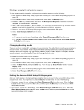
... option. 6. headphones or a microphone) are bootable. 1. Start the Setup Utility program (see "Starting the Setup Utility program" on the computer. 3. Note: Selecting a startup device from the menu. SATA Mode Onboard Audio Controller Onboard Ethernet Controller or LAN Boot Agent Select Disabled/IDE/AHCI mode. Press and hold the F12 key then turn on how the hard disk drive image was installed, changing this procedure to enable or disable load onboard PXE (Preboot Execution Environment). Select Network Setup, press the Enter key, then select Onboard Ethernet Support...
... option. 6. headphones or a microphone) are bootable. 1. Start the Setup Utility program (see "Starting the Setup Utility program" on the computer. 3. Note: Selecting a startup device from the menu. SATA Mode Onboard Audio Controller Onboard Ethernet Controller or LAN Boot Agent Select Disabled/IDE/AHCI mode. Press and hold the F12 key then turn on how the hard disk drive image was installed, changing this procedure to enable or disable load onboard PXE (Preboot Execution Environment). Select Network Setup, press the Enter key, then select Onboard Ethernet Support...
Hardware Maintenance Manual
Page 23
... Startup option. 3. Return to the Lenovo BIOS Setup Utility program menu and select the Exit option. 5. Select the Boot Priority, then press Enter key. Do one of the screen. 4. Using the Setup Utility 17 The legacy Windows operating system cannot be installed if you must change the boot mode. To change the configured startup device sequence, do the following: 1. Start the Lenovo BIOS Setup Utility program (see "Starting the Lenovo BIOS Setup Utility program" on your computer, you don't change the boot mode to save the new settings, select Save Changes...
... Startup option. 3. Return to the Lenovo BIOS Setup Utility program menu and select the Exit option. 5. Select the Boot Priority, then press Enter key. Do one of the screen. 4. Using the Setup Utility 17 The legacy Windows operating system cannot be installed if you must change the boot mode. To change the configured startup device sequence, do the following: 1. Start the Lenovo BIOS Setup Utility program (see "Starting the Lenovo BIOS Setup Utility program" on your computer, you don't change the boot mode to save the new settings, select Save Changes...

Hardware Maintenance Manual
Page 25
... the boot sequence configuration. Attempt to correct the problem using this index. The most likely cause is defective. No operating system is installed on the startup drive is not included in the boot sequence. The drive is listed first. The boot sector on the boot drive. Error The startup drive is corrupted. Check the power-on the boot drive. Install an operating system on switch. FRU/Action Reseat connectors Power Cord Power-on page 20. Power Supply Problems Follow...
... the boot sequence configuration. Attempt to correct the problem using this index. The most likely cause is defective. No operating system is installed on the startup drive is not included in the boot sequence. The drive is listed first. The boot sector on the boot drive. Error The startup drive is corrupted. Check the power-on the boot drive. Install an operating system on switch. FRU/Action Reseat connectors Power Cord Power-on page 20. Power Supply Problems Follow...
Hardware Maintenance Manual
Page 26
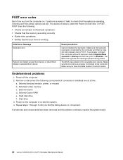
... problem continues, replace the system board. 20 Lenovo C240/245 All-In-One PC Hardware Maintenance Manual Remove or disconnect the following : • Checks some basic motherboard operations • Checks that the memory is working correctly • Starts video operations • Verifies that the boot drive is working POST Error Message Keyboard error Reboot and Select proper Boot device or Insert Boot Media in Startup and set . Make sure the keyboard is properly connected to the computer. Hard disk drive f. Power-on , it performs a series of tests is operating...
... problem continues, replace the system board. 20 Lenovo C240/245 All-In-One PC Hardware Maintenance Manual Remove or disconnect the following : • Checks some basic motherboard operations • Checks that the memory is working correctly • Starts video operations • Verifies that the boot drive is working POST Error Message Keyboard error Reboot and Select proper Boot device or Insert Boot Media in Startup and set . Make sure the keyboard is properly connected to the computer. Hard disk drive f. Power-on , it performs a series of tests is operating...
Hardware Maintenance Manual
Page 30
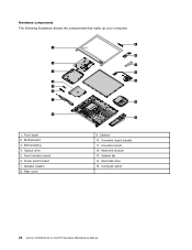
Power switch board 7. Hardware components The following illustration shows the components that make up your computer. 9 1 10 2 11 3 12 4 13 5 6 7 14 8 15 1. Speaker system 8. System fan 14. Camera 10. Front bezel 2. EMI shielding 4. Heat-sink module 13. Motherboard 3. Optical drive 5. Front indicator board 6. Converter board bracket 11. Hard disk drive 15. Converter board 12. Rear cover 9. Computer stand 24 Lenovo C240/245 All-In-One PC Hardware Maintenance Manual
Power switch board 7. Hardware components The following illustration shows the components that make up your computer. 9 1 10 2 11 3 12 4 13 5 6 7 14 8 15 1. Speaker system 8. System fan 14. Camera 10. Front bezel 2. EMI shielding 4. Heat-sink module 13. Motherboard 3. Optical drive 5. Front indicator board 6. Converter board bracket 11. Hard disk drive 15. Converter board 12. Rear cover 9. Computer stand 24 Lenovo C240/245 All-In-One PC Hardware Maintenance Manual
Hardware Maintenance Manual
Page 34
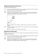
... the same connector. Remove any media (disks, CDs, DVDs, or memory cards) from the drives, shut down the operating system, and turn off the computer and all power cords from electrical outlets. This includes power cords, input/output (I /O) cables, and any other cables that are connected to "Left and right view" and "Rear view" for help with locating the various connectors. 28 Lenovo C240/245 All-In-One PC Hardware Maintenance Manual Step...
... the same connector. Remove any media (disks, CDs, DVDs, or memory cards) from the drives, shut down the operating system, and turn off the computer and all power cords from electrical outlets. This includes power cords, input/output (I /O) cables, and any other cables that are connected to "Left and right view" and "Rear view" for help with locating the various connectors. 28 Lenovo C240/245 All-In-One PC Hardware Maintenance Manual Step...
Hardware Maintenance Manual
Page 36
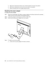
... PC Hardware Maintenance Manual Step 3. Align the new optical drive with the cover, and then push the cover back into position. Remove any media (disks, CDs, DVDs, or memory cards) from the computer. Step 4. Replacing the power adapter To replace the power adapter: Step 1. Locate the connector for the power cord. Connect the new power adapter to the chassis using the screw. Disconnect the failing power adapter from the drives, shut down the operating system, and turn off the computer and all attached devices...
... PC Hardware Maintenance Manual Step 3. Align the new optical drive with the cover, and then push the cover back into position. Remove any media (disks, CDs, DVDs, or memory cards) from the computer. Step 4. Replacing the power adapter To replace the power adapter: Step 1. Locate the connector for the power cord. Connect the new power adapter to the chassis using the screw. Disconnect the failing power adapter from the drives, shut down the operating system, and turn off the computer and all attached devices...

Hardware Maintenance Manual
Page 39
... the new hard disk drive to the computer. Reattach the rear cover and secure it . 2 2 1 Step 8. To replace the heat-sink: Step 1. Step 5. Step 4. To install the new hard disk drive: a. Step 4. Disconnect all cables attached to the rear cover with the 4 screws. b. d. Remove any other cables that are connected to "Removing the rear cover". This includes power cords, input/output (I /O) cables, and any media (disks, CDs, DVDs or memory cards) from the drives, shut down before removing the rear cover. Remove the rear cover.
... the new hard disk drive to the computer. Reattach the rear cover and secure it . 2 2 1 Step 8. To replace the heat-sink: Step 1. Step 5. Step 4. To install the new hard disk drive: a. Step 4. Disconnect all cables attached to the rear cover with the 4 screws. b. d. Remove any other cables that are connected to "Removing the rear cover". This includes power cords, input/output (I /O) cables, and any media (disks, CDs, DVDs or memory cards) from the drives, shut down before removing the rear cover. Remove the rear cover.

Hardware Maintenance Manual
Page 45
... rear cover". b. Remove all attached devices. Step 7. Refer to "Replacing the heat-sink". Refer to the connector on the rear cover and secure the new power switch board with the screws. Replacing hardware 39 Step 5. Disconnect the power switch board cable from electrical outlets. Connect the data cable to "Left and right view" and "Rear view" for help with locating the various connectors. Step 3. This includes power cords, input/output (I/O) cables, and any media (disks, CDs, DVDs, or memory cards...
... rear cover". b. Remove all attached devices. Step 7. Refer to "Replacing the heat-sink". Refer to the connector on the rear cover and secure the new power switch board with the screws. Replacing hardware 39 Step 5. Disconnect the power switch board cable from electrical outlets. Connect the data cable to "Left and right view" and "Rear view" for help with locating the various connectors. Step 3. This includes power cords, input/output (I/O) cables, and any media (disks, CDs, DVDs, or memory cards...

Hardware Maintenance Manual
Page 49
... includes power cords, input/output (I/O) cables, and any media (disks, CDs, DVDs, or memory cards) from the drives, shut down the operating system, and turn off the computer and wait 3 to 5 minutes to the computer. Remove the converter board. Step 7. Refer to the new converter board. Replacing hardware 43 Disconnect the 2 cables from electrical outlets. Connect the 2 cables to "Removing the rear cover". Chapter 8. Step 6. To install the new converter board: a. b. Line up the converter board...
... includes power cords, input/output (I/O) cables, and any media (disks, CDs, DVDs, or memory cards) from the drives, shut down the operating system, and turn off the computer and wait 3 to 5 minutes to the computer. Remove the converter board. Step 7. Refer to the new converter board. Replacing hardware 43 Disconnect the 2 cables from electrical outlets. Connect the 2 cables to "Removing the rear cover". Chapter 8. Step 6. To install the new converter board: a. b. Line up the converter board...


