Hardware Maintenance Manual
Page 5
...-Fi card 35 Replacing the speaker system 36 Replacing the front indicator board 37 Replacing the power switch board 38 Replacing the motherboard 39 Replacing the computer stand 41 Replacing the camera 41 Replacing the converter board 42 Replacing the LED panel 43 FRU lists ...45 Chapter 9. Additional Service Information 49 © Copyright Lenovo 2012 iii Using the Setup Utility. . . 13 Starting the Lenovo BIOS Setup Utility program . 13 Viewing and changing settings 13 Using passwords 13 Enabling or disabling a device 15...
...-Fi card 35 Replacing the speaker system 36 Replacing the front indicator board 37 Replacing the power switch board 38 Replacing the motherboard 39 Replacing the computer stand 41 Replacing the camera 41 Replacing the converter board 42 Replacing the LED panel 43 FRU lists ...45 Chapter 9. Additional Service Information 49 © Copyright Lenovo 2012 iii Using the Setup Utility. . . 13 Starting the Lenovo BIOS Setup Utility program . 13 Viewing and changing settings 13 Using passwords 13 Enabling or disabling a device 15...
Hardware Maintenance Manual
Page 26
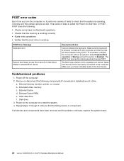
... (if connected or installed) one at a time. The BIOS then ignores the missing keyboard during POST. Remove or disconnect the following : • Checks some basic motherboard operations • Checks that the memory is operating correctly and that certain options are held pressed during POST. External devices (modem, printer, or mouse) b. POST... performs a series of tests is properly connected to the computer. Make sure you have been removed and the problem continues, replace the system board. 20 Lenovo C240/245 All-In-One PC Hardware Maintenance Manual
... (if connected or installed) one at a time. The BIOS then ignores the missing keyboard during POST. Remove or disconnect the following : • Checks some basic motherboard operations • Checks that the memory is operating correctly and that certain options are held pressed during POST. External devices (modem, printer, or mouse) b. POST... performs a series of tests is properly connected to the computer. Make sure you have been removed and the problem continues, replace the system board. 20 Lenovo C240/245 All-In-One PC Hardware Maintenance Manual
Hardware Maintenance Manual
Page 30
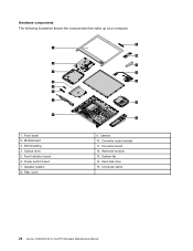
Front indicator board 6. Optical drive 5. Rear cover 9. Converter board bracket 11. Hardware components The following illustration shows the components that make up your computer. 9 1 10 2 11 3 12 4 13 5 6 7 14 8 15 1. EMI shielding 4. Heat-sink module 13. Hard disk drive 15. Power switch board 7. Motherboard 3. Converter board 12. Computer stand 24 Lenovo C240/245 All-In-One PC Hardware Maintenance Manual Speaker system 8. System fan 14. Camera 10. Front bezel 2.
Front indicator board 6. Optical drive 5. Rear cover 9. Converter board bracket 11. Hardware components The following illustration shows the components that make up your computer. 9 1 10 2 11 3 12 4 13 5 6 7 14 8 15 1. EMI shielding 4. Heat-sink module 13. Hard disk drive 15. Power switch board 7. Motherboard 3. Converter board 12. Computer stand 24 Lenovo C240/245 All-In-One PC Hardware Maintenance Manual Speaker system 8. System fan 14. Camera 10. Front bezel 2.

Hardware Maintenance Manual
Page 31
... front of devices that are factory-installed or that can be installed later. The following illustration shows the location of connectors and components on the motherboard The motherboard (sometimes called the planar or system board) is the main circuit board in your computer. TV-Tuner card port 7. System fan connector 5. Memory slots...
... front of devices that are factory-installed or that can be installed later. The following illustration shows the location of connectors and components on the motherboard The motherboard (sometimes called the planar or system board) is the main circuit board in your computer. TV-Tuner card port 7. System fan connector 5. Memory slots...
Hardware Maintenance Manual
Page 40
...motherboard. b. Step 3. Remove the rear cover. Lift up the new heat-sink module with locating the various connectors. Disconnect all attached devices. Refer to let it cool down before removing the rear cover. Use the adhesive tape to "Removing the rear cover". 34 Lenovo C240... all cables attached to the computer. Replacing the system fan Note: Turn off the CPU. d. Secure the new heat-sink to the motherboard. Remove any other components. Remove the 4 screws that are connected to the computer. This includes power cords, input/output (I/O) cables, ...
...motherboard. b. Step 3. Remove the rear cover. Lift up the new heat-sink module with locating the various connectors. Disconnect all attached devices. Refer to let it cool down before removing the rear cover. Use the adhesive tape to "Removing the rear cover". 34 Lenovo C240... all cables attached to the computer. Replacing the system fan Note: Turn off the CPU. d. Secure the new heat-sink to the motherboard. Remove any other components. Remove the 4 screws that are connected to the computer. This includes power cords, input/output (I/O) cables, ...

Hardware Maintenance Manual
Page 41
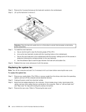
...2 screws. Replacing the Wi-Fi card Note: Turn off the computer and wait 3 to 5 minutes to let it with the mounting holes on the motherboard. Replacing hardware 35 Disconnect all attached devices. Refer to the computer. Lift up the new system fan with the screws. Secure the new system fan.... Refer to the rear cover. Step 7. Step 4. To replace the Wi-Fi card: Step 1. Disconnect the power cable from the connector on the motherboard. 1 Remove the 2 screws that are connected to the connector on the rear cover and place it . 2 1 2 Step 8. Remove the rear cover.
...2 screws. Replacing the Wi-Fi card Note: Turn off the computer and wait 3 to 5 minutes to let it with the mounting holes on the motherboard. Replacing hardware 35 Disconnect all attached devices. Refer to the computer. Lift up the new system fan with the screws. Secure the new system fan.... Refer to the rear cover. Step 7. Step 4. To replace the Wi-Fi card: Step 1. Disconnect the power cable from the connector on the motherboard. 1 Remove the 2 screws that are connected to the connector on the rear cover and place it . 2 1 2 Step 8. Remove the rear cover.
Hardware Maintenance Manual
Page 42
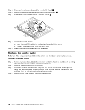
... the computer and all attached devices. To replace the speaker system: Step 1. Step 3. Remove any other cables that secures the Wi-Fi card to the motherboard. 2 Pull the Wi-Fi card upward to remove it cool down the operating system, and turn off the computer and wait 3 to 5 minutes to "Left... all cables attached to the computer. Step 4. Refer to the new Wi-Fi card. Step 5. Connect the antenna cables to "Removing the rear cover". 36 Lenovo C240/245 All-In-One PC Hardware Maintenance Manual Step 7.
... the computer and all attached devices. To replace the speaker system: Step 1. Step 3. Remove any other cables that secures the Wi-Fi card to the motherboard. 2 Pull the Wi-Fi card upward to remove it cool down the operating system, and turn off the computer and wait 3 to 5 minutes to "Left... all cables attached to the computer. Step 4. Refer to the new Wi-Fi card. Step 5. Connect the antenna cables to "Removing the rear cover". 36 Lenovo C240/245 All-In-One PC Hardware Maintenance Manual Step 7.

Hardware Maintenance Manual
Page 43
Step 8. Step 3. Remove any other cables that are connected to the connector on motherboard. 1 Step 6. Chapter 8. Step 5. To install the new speaker system: a. Connect the new speaker cable to the computer. This includes power cords, input/output (I/O) cables,... and any media (disks, CDs, DVDs, or memory cards) from the connector on the motherboard. Refer to let it with the rubber screws. Replacing hardware 37 Reattach the rear cover and secure it cool down the operating system, and turn...
Step 8. Step 3. Remove any other cables that are connected to the connector on motherboard. 1 Step 6. Chapter 8. Step 5. To install the new speaker system: a. Connect the new speaker cable to the computer. This includes power cords, input/output (I/O) cables,... and any media (disks, CDs, DVDs, or memory cards) from the connector on the motherboard. Refer to let it with the rubber screws. Replacing hardware 37 Reattach the rear cover and secure it cool down the operating system, and turn...
Hardware Maintenance Manual
Page 44
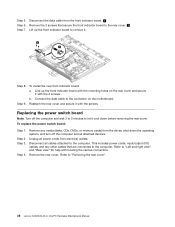
Connect the data cable to "Removing the rear cover". 38 Lenovo C240/245 All-In-One PC Hardware Maintenance Manual Reattach the rear cover and secure it . 2 1 Step 8. Disconnect all attached devices. Refer to the computer. Replacing ... the screws. Step 7. Line up the front indicator board to the rear cover. 2 Lift up the front indicator board with the mounting holes on the motherboard. To replace the power switch board: Step 1. Remove any other cables that secure the front indicator board to remove it with locating the various connectors...
Connect the data cable to "Removing the rear cover". 38 Lenovo C240/245 All-In-One PC Hardware Maintenance Manual Reattach the rear cover and secure it . 2 1 Step 8. Disconnect all attached devices. Refer to the computer. Replacing ... the screws. Step 7. Line up the front indicator board to the rear cover. 2 Lift up the front indicator board with the mounting holes on the motherboard. To replace the power switch board: Step 1. Remove any other cables that secure the front indicator board to remove it with locating the various connectors...

Hardware Maintenance Manual
Page 45
... modules. Remove the rear cover. Refer to "Replacing the heat-sink". Chapter 8. Remove the screw that are connected to the connector on the motherboard. 1 Step 6. Connect the data cable to the computer. Step 4. Refer to "Replacing a memory module". Refer to "Removing the rear cover...". Replacing hardware 39 Unplug all attached devices. Remove the heat-sink. b. Replacing the motherboard Note: Turn off the computer and wait 3 to 5 minutes to the rear cover and lift up the holes on the new power switch ...
... modules. Remove the rear cover. Refer to "Replacing the heat-sink". Chapter 8. Remove the screw that are connected to the connector on the motherboard. 1 Step 6. Connect the data cable to the computer. Step 4. Refer to "Replacing a memory module". Refer to "Removing the rear cover...". Replacing hardware 39 Unplug all attached devices. Remove the heat-sink. b. Replacing the motherboard Note: Turn off the computer and wait 3 to 5 minutes to the rear cover and lift up the holes on the new power switch ...

Hardware Maintenance Manual
Page 46
... 9. Insert the notched end of the Wi-Fi card into the card port on the rear cover and secure the new motherboard with the screws. 40 Lenovo C240/245 All-In-One PC Hardware Maintenance Manual c. e. Connect all the cables connected to the rear cover and lift it up the holes on the... new motherboard with the mounting holes on the new motherboard and secure it with the screw. Remove all the cables to remove it ...
... 9. Insert the notched end of the Wi-Fi card into the card port on the rear cover and secure the new motherboard with the screws. 40 Lenovo C240/245 All-In-One PC Hardware Maintenance Manual c. e. Connect all the cables connected to the rear cover and lift it up the holes on the... new motherboard with the mounting holes on the new motherboard and secure it with the screw. Remove all the cables to remove it ...
Hardware Maintenance Manual
Page 52
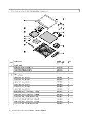
...are not to be replaced by the customer. 1 2 3 4 5 6 7 8 Item# Description 1 Front bezel C240 FRONT BEZEL(BLACKE) C240 FRONT BEZEL(WHITE) 2 Motherboard C240 NOK CPU_847 MB C240 NOK CPU_807 MB C240 W8P CPU_847 MB C240 W8P CPU_807 MB C240 W8S CPU_847 MB C240 W8S CPU_807 MB C245 NOK UMA CPU_E2-1800 1.7G MB C245 NOK UMA CPU_E1-1200...-450 1.65G MB C245 W8P UMA CPU_E2-1800 1.7G MB C245 W8P UMA CPU_E1-1200 1.4G MB C245 W8P UMA CPU_E-450 1.65G MB 46 Lenovo C240/245 All-In-One PC Hardware Maintenance Manual 9 10 11 12 13 14 15 Service Part CRU Number (FRU) ID 90202143 N 90202144 N 90001861 N ...
...are not to be replaced by the customer. 1 2 3 4 5 6 7 8 Item# Description 1 Front bezel C240 FRONT BEZEL(BLACKE) C240 FRONT BEZEL(WHITE) 2 Motherboard C240 NOK CPU_847 MB C240 NOK CPU_807 MB C240 W8P CPU_847 MB C240 W8P CPU_807 MB C240 W8S CPU_847 MB C240 W8S CPU_807 MB C245 NOK UMA CPU_E2-1800 1.7G MB C245 NOK UMA CPU_E1-1200...-450 1.65G MB C245 W8P UMA CPU_E2-1800 1.7G MB C245 W8P UMA CPU_E1-1200 1.4G MB C245 W8P UMA CPU_E-450 1.65G MB 46 Lenovo C240/245 All-In-One PC Hardware Maintenance Manual 9 10 11 12 13 14 15 Service Part CRU Number (FRU) ID 90202143 N 90202144 N 90001861 N ...


