Hardware Maintenance Manual
Page 3
...statement (multilingual translations 19 Chapter 2. Lenovo B490 37 Specifications 37 Status indicators 38 Fn key combinations 39 Chapter 6. Contents About this manual iii Chapter 1. FRU replacement notices 41 Screw notices 41 Chapter 7. Parts list 79 Overall 80 LCD FRUs 83 Keyboard 85 Miscellaneous parts 87 ac power ... . 28 Important notice for wireless LAN . . 49 1070 mSATA solid state drive 50 1080 Backup battery 51 1090 Keyboard 51 1100 Keyboard bezel 54 1110 LED board 56 1120 Power board 57 1130 Microphone assembly 58 1140 I/O board 59 1150 System board ...
...statement (multilingual translations 19 Chapter 2. Lenovo B490 37 Specifications 37 Status indicators 38 Fn key combinations 39 Chapter 6. Contents About this manual iii Chapter 1. FRU replacement notices 41 Screw notices 41 Chapter 7. Parts list 79 Overall 80 LCD FRUs 83 Keyboard 85 Miscellaneous parts 87 ac power ... . 28 Important notice for wireless LAN . . 49 1070 mSATA solid state drive 50 1080 Backup battery 51 1090 Keyboard 51 1100 Keyboard bezel 54 1110 LED board 56 1120 Power board 57 1130 Microphone assembly 58 1140 I/O board 59 1150 System board ...
Hardware Maintenance Manual
Page 36
... the voltage is acceptable, do the following: • Replace the system board. • If the problem persists, go to Chapter 5 "Lenovo B490" on page 37. 30 Hardware Maintenance Manual Disconnect the ac power adapter and install the charged battery pack. 7. Connect the ac power adapter...a nonsupported device • Forgotten computer password (making the computer unusable) • Sticky keys caused by spilling a liquid onto the keyboard • Use of an incorrect ac power adapter on laptop products The following symptoms might indicate damage caused by nonwarranted activities: •...
... the voltage is acceptable, do the following: • Replace the system board. • If the problem persists, go to Chapter 5 "Lenovo B490" on page 37. 30 Hardware Maintenance Manual Disconnect the ac power adapter and install the charged battery pack. 7. Connect the ac power adapter...a nonsupported device • Forgotten computer password (making the computer unusable) • Sticky keys caused by spilling a liquid onto the keyboard • Use of an incorrect ac power adapter on laptop products The following symptoms might indicate damage caused by nonwarranted activities: •...
Hardware Maintenance Manual
Page 40
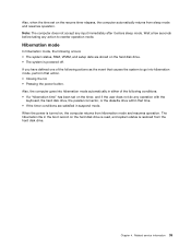
... operation, press Fn+F2. Power-on password A power-on password protects the system from sleep mode and resume the operation, do any operation with the keyboard, the hard disk drive, the parallel connector, or the diskette drive within that time. • If the battery indicator blinks orange, indicating that the battery...
... operation, press Fn+F2. Power-on password A power-on password protects the system from sleep mode and resume the operation, do any operation with the keyboard, the hard disk drive, the parallel connector, or the diskette drive within that time. • If the battery indicator blinks orange, indicating that the battery...
Hardware Maintenance Manual
Page 41
... drive. Related service information 35 Chapter 4. Also, when the time set on the timer, and if the user does not do any operation with the keyboard, the hard disk drive, the parallel connector, or the diskette drive within that action. • Closing the lid. • Pressing the power button. Wait a few...
... drive. Related service information 35 Chapter 4. Also, when the time set on the timer, and if the user does not do any operation with the keyboard, the hard disk drive, the parallel connector, or the diskette drive within that action. • Closing the lid. • Pressing the power button. Wait a few...
Hardware Maintenance Manual
Page 43
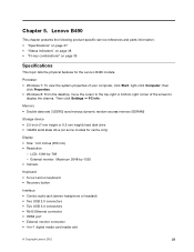
...Keyboard • 6-row Lenovo keyboard • Recovery button Interface • Combo audio jack (stereo headphone or headset) • Two USB 2.0 connectors • Two USB 3.0 connectors • RJ45 Ethernet connector • HDMI port • External monitor connector • 4-in-1 digital media card reader slot © Copyright Lenovo 2012 37 Lenovo B490... 37 • "Status indicators" on page 38 • "Fn key combinations" on some models for the Lenovo B490 models. Chapter 5. Processor • Windows 7: To view the system properties of the screen to display the charms. Then ...
...Keyboard • 6-row Lenovo keyboard • Recovery button Interface • Combo audio jack (stereo headphone or headset) • Two USB 2.0 connectors • Two USB 3.0 connectors • RJ45 Ethernet connector • HDMI port • External monitor connector • 4-in-1 digital media card reader slot © Copyright Lenovo 2012 37 Lenovo B490... 37 • "Status indicators" on page 38 • "Fn key combinations" on some models for the Lenovo B490 models. Chapter 5. Processor • Windows 7: To view the system properties of the screen to display the charms. Then ...
Hardware Maintenance Manual
Page 44
... • Integrated wireless LAN • Integrated Bluetooth (on some models) • Integrated WiMAX • 100/1000 Mbps Ethernet communication Security feature Fingerprint Reader (on the keyboard is enabled.
... • Integrated wireless LAN • Integrated Bluetooth (on some models) • Integrated WiMAX • 100/1000 Mbps Ethernet communication Security feature Fingerprint Reader (on the keyboard is enabled.
Hardware Maintenance Manual
Page 45
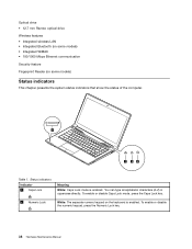
... 2. To resume normal operation, press the Fn key only. Has the same function as the SysRq key on a conventional keyboard. When the battery charge level reaches 80%, the battery status indicator stops blinking, but the charging might cause drive errors....move the computer. Enables or disables the numeric keypad. Has the same function as the Pause key on a conventional keyboard. Puts the computer into sleep mode or turn off the computer. • When the indicator is powered off. Note...control: Skip to the next track Enables or disables the scroll lock function. Lenovo B490 39
... 2. To resume normal operation, press the Fn key only. Has the same function as the SysRq key on a conventional keyboard. When the battery charge level reaches 80%, the battery status indicator stops blinking, but the charging might cause drive errors....move the computer. Enables or disables the numeric keypad. Has the same function as the Pause key on a conventional keyboard. Puts the computer into sleep mode or turn off the computer. • When the indicator is powered off. Note...control: Skip to the next track Enables or disables the scroll lock function. Lenovo B490 39
Hardware Maintenance Manual
Page 46
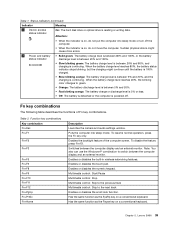
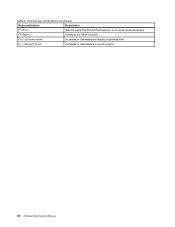
Function key combinations (continued) Key combination Description Fn+End Has the same function as the Break key on a conventional keyboard. Fn + up/down arrow Increases or decreases the display brightness level. Fn + left/right arrow Increases or decreases the sound volume. 40 Hardware Maintenance Manual Fn+PgDn Activates the insert function. Table 2.
Function key combinations (continued) Key combination Description Fn+End Has the same function as the Break key on a conventional keyboard. Fn + up/down arrow Increases or decreases the display brightness level. Fn + left/right arrow Increases or decreases the sound volume. 40 Hardware Maintenance Manual Fn+PgDn Activates the insert function. Table 2.
Hardware Maintenance Manual
Page 57
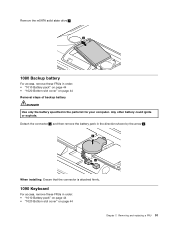
... the connector 1 , and then remove the battery pack in the direction shown by the arrow 2 . 2 1 When installing: Ensure that the connector is attached firmly. 1090 Keyboard For access, remove these FRUs in order: • "1010 Battery pack" on page 44 • "1020 Bottom slot cover" on page 44 Removal steps of...
... the connector 1 , and then remove the battery pack in the direction shown by the arrow 2 . 2 1 When installing: Ensure that the connector is attached firmly. 1090 Keyboard For access, remove these FRUs in order: • "1010 Battery pack" on page 44 • "1020 Bottom slot cover" on page 44 Removal steps of...
Hardware Maintenance Manual
Page 58
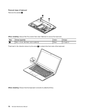
Removal steps of the keyboard. 2 When installing: Ensure that the screws have been fastened to secure the keyboard. Step 1 Screw (quantity) M2.5 × 8 mm, flat-head, nylon-coated (3) Color Black Torque 4.0 kgf-cm Push hard in the direction shown by the arrow 2 to unlatch the front side of keyboard Remove the screws 1 . 1 1 1 When installing: Ensure that the keyboard connector is attached firmly. 52 Hardware Maintenance Manual
Removal steps of the keyboard. 2 When installing: Ensure that the screws have been fastened to secure the keyboard. Step 1 Screw (quantity) M2.5 × 8 mm, flat-head, nylon-coated (3) Color Black Torque 4.0 kgf-cm Push hard in the direction shown by the arrow 2 to unlatch the front side of keyboard Remove the screws 1 . 1 1 1 When installing: Ensure that the keyboard connector is attached firmly. 52 Hardware Maintenance Manual
Hardware Maintenance Manual
Page 59
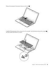
Hold the keyboard above the computer 4 , and then detach the keyboard connector. 4 6 5 Chapter 7. Remove the keyboard in the direction shown by the arrow 3 . 3 Carefully lift the keyboard until you can see how it's connected. Removing and replacing a FRU 53
Hold the keyboard above the computer 4 , and then detach the keyboard connector. 4 6 5 Chapter 7. Remove the keyboard in the direction shown by the arrow 3 . 3 Carefully lift the keyboard until you can see how it's connected. Removing and replacing a FRU 53
Hardware Maintenance Manual
Page 60
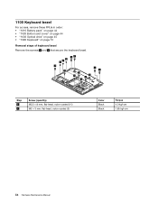
1100 Keyboard bezel For access, remove these FRUs in order: • "1010 Battery pack" on page 44 • "1020 Bottom slot cover" on page 44 • "1030 Optical drive" on page 45 • "1090 Keyboard" on page 51 Removal steps of keyboard bezel Remove the screws 1 and 2 that secure the keyboard bezel. 2 2 2 11 1 1 1 1 1 1 1 1 1 Step 1 2 Screw (quantity) M2.5 × 8 mm, flat-head, nylon-coated (11) M2 × 3 mm, flat-head, nylon-coated (3) Color Black Black Torque 4.0 kgf-cm 1.85 kgf-cm 54 Hardware Maintenance Manual
1100 Keyboard bezel For access, remove these FRUs in order: • "1010 Battery pack" on page 44 • "1020 Bottom slot cover" on page 44 • "1030 Optical drive" on page 45 • "1090 Keyboard" on page 51 Removal steps of keyboard bezel Remove the screws 1 and 2 that secure the keyboard bezel. 2 2 2 11 1 1 1 1 1 1 1 1 1 Step 1 2 Screw (quantity) M2.5 × 8 mm, flat-head, nylon-coated (11) M2 × 3 mm, flat-head, nylon-coated (3) Color Black Black Torque 4.0 kgf-cm 1.85 kgf-cm 54 Hardware Maintenance Manual
Hardware Maintenance Manual
Page 62
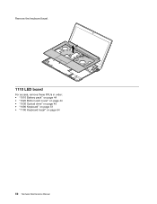
Remove the keyboard bezel. 10 1110 LED board For access, remove these FRUs in order: • "1010 Battery pack" on page 44 • "1020 Bottom slot cover" on page 44 • "1030 Optical drive" on page 45 • "1090 Keyboard" on page 51 • "1100 Keyboard bezel" on page 54 56 Hardware Maintenance Manual
Remove the keyboard bezel. 10 1110 LED board For access, remove these FRUs in order: • "1010 Battery pack" on page 44 • "1020 Bottom slot cover" on page 44 • "1030 Optical drive" on page 45 • "1090 Keyboard" on page 51 • "1100 Keyboard bezel" on page 54 56 Hardware Maintenance Manual
Hardware Maintenance Manual
Page 63
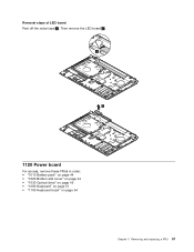
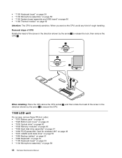
Removing and replacing a FRU 57 Then remove the LED board 2 . 1 2 1120 Power board For access, remove these FRUs in order: • "1010 Battery pack" on page 44 • "1020 Bottom slot cover" on page 44 • "1030 Optical drive" on page 45 • "1090 Keyboard" on page 51 • "1100 Keyboard bezel" on page 54 Chapter 7. Removal steps of LED board Peel off the mylar tape 1 .
Removing and replacing a FRU 57 Then remove the LED board 2 . 1 2 1120 Power board For access, remove these FRUs in order: • "1010 Battery pack" on page 44 • "1020 Bottom slot cover" on page 44 • "1030 Optical drive" on page 45 • "1090 Keyboard" on page 51 • "1100 Keyboard bezel" on page 54 Chapter 7. Removal steps of LED board Peel off the mylar tape 1 .
Hardware Maintenance Manual
Page 64
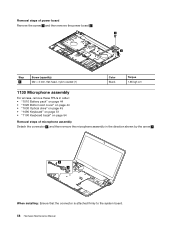
... Battery pack" on page 44 • "1020 Bottom slot cover" on page 44 • "1030 Optical drive" on page 45 • "1090 Keyboard" on page 51 • "1100 Keyboard bezel" on page 54 Removal steps of microphone assembly Detach the connector 1 , and then remove the microphone assembly in the direction shown by...
... Battery pack" on page 44 • "1020 Bottom slot cover" on page 44 • "1030 Optical drive" on page 45 • "1090 Keyboard" on page 51 • "1100 Keyboard bezel" on page 54 Removal steps of microphone assembly Detach the connector 1 , and then remove the microphone assembly in the direction shown by...
Hardware Maintenance Manual
Page 65
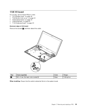
Removing and replacing a FRU 59 1140 I/O board For access, remove these FRUs in order: • "1010 Battery pack" on page 44 • "1020 Bottom slot cover" on page 44 • "1030 Optical drive" on page 45 • "1090 Keyboard" on page 51 • "1100 Keyboard bezel" on page 54 Removal steps of I/O board Remove the screws 1 , and then detach the cable. 1 1 2 3 Step 1 Screw (quantity) M2 × 6 mm, flat-head, nylon-coated (2) Color Black When installing: Ensure that the cable is attached firmly to the system board. Torque 1.85 kgf-cm Chapter 7.
Removing and replacing a FRU 59 1140 I/O board For access, remove these FRUs in order: • "1010 Battery pack" on page 44 • "1020 Bottom slot cover" on page 44 • "1030 Optical drive" on page 45 • "1090 Keyboard" on page 51 • "1100 Keyboard bezel" on page 54 Removal steps of I/O board Remove the screws 1 , and then detach the cable. 1 1 2 3 Step 1 Screw (quantity) M2 × 6 mm, flat-head, nylon-coated (2) Color Black When installing: Ensure that the cable is attached firmly to the system board. Torque 1.85 kgf-cm Chapter 7.
Hardware Maintenance Manual
Page 66
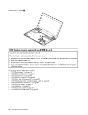
... Card for wireless LAN" on page 49 • "1070 mSATA solid state drive" on page 50 • "1080 Backup battery" on page 51 • "1090 Keyboard" on page 51 • "1100 Keyboard bezel" on page 54 • "1130 Microphone assembly" on a padded surface such as an ESD mat or a corrugated conductive surface.
... Card for wireless LAN" on page 49 • "1070 mSATA solid state drive" on page 50 • "1080 Backup battery" on page 51 • "1090 Keyboard" on page 51 • "1100 Keyboard bezel" on page 54 • "1130 Microphone assembly" on a padded surface such as an ESD mat or a corrugated conductive surface.
Hardware Maintenance Manual
Page 68
... LAN" on page 49 • "1070 mSATA solid state drive" on page 50 • "1080 Backup battery" on page 51 • "1090 Keyboard" on page 51 • "1100 Keyboard bezel" on page 54 • "1130 Microphone assembly" on page 58 • "1150 System board assembly and USB board" on page 60 62...
... LAN" on page 49 • "1070 mSATA solid state drive" on page 50 • "1080 Backup battery" on page 51 • "1090 Keyboard" on page 51 • "1100 Keyboard bezel" on page 54 • "1130 Microphone assembly" on page 58 • "1150 System board assembly and USB board" on page 60 62...
Hardware Maintenance Manual
Page 71
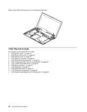
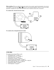
... Card for wireless LAN" on page 49 • "1070 mSATA solid state drive" on page 50 • "1080 Backup battery" on page 51 • "1090 Keyboard" on page 51 Chapter 7. For models with a discrete thermal module a b For models with a component. Removing and replacing a FRU 65 When installing: Before you attach the...
... Card for wireless LAN" on page 49 • "1070 mSATA solid state drive" on page 50 • "1080 Backup battery" on page 51 • "1090 Keyboard" on page 51 Chapter 7. For models with a discrete thermal module a b For models with a component. Removing and replacing a FRU 65 When installing: Before you attach the...
Hardware Maintenance Manual
Page 72
... Card for wireless LAN" on page 49 • "1070 mSATA solid state drive" on page 50 • "1080 Backup battery" on page 51 • "1090 Keyboard" on page 51 • "1100 Keyboard bezel" on page 54 • "1130 Microphone assembly" on page 62 Attention: The CPU is extremely sensitive. • "1100... Keyboard bezel" on page 54 • "1130 Microphone assembly" on page 58 • "1150 System board assembly and USB board" on page 60 • "1160 Thermal ...
... Card for wireless LAN" on page 49 • "1070 mSATA solid state drive" on page 50 • "1080 Backup battery" on page 51 • "1090 Keyboard" on page 51 • "1100 Keyboard bezel" on page 54 • "1130 Microphone assembly" on page 62 Attention: The CPU is extremely sensitive. • "1100... Keyboard bezel" on page 54 • "1130 Microphone assembly" on page 58 • "1150 System board assembly and USB board" on page 60 • "1160 Thermal ...


