Hardware Maintenance Manual
Page 3
... for replacing a hard disk drive . . . 28 Important notice for wireless LAN . . 49 1070 mSATA solid state drive 50 1080 Backup battery 51 1090 Keyboard 51 1100 Keyboard bezel 54 1110 LED board 56 1120 Power board 57 1130 Microphone assembly 58 1140 I/O board 59 1150 System board assembly and USB board . . 60 1160 Thermal module 62 1170 CPU 65 1180 LCD unit 66 1190 Speaker assembly 68 1200 DC-in connector and base cover...
... for replacing a hard disk drive . . . 28 Important notice for wireless LAN . . 49 1070 mSATA solid state drive 50 1080 Backup battery 51 1090 Keyboard 51 1100 Keyboard bezel 54 1110 LED board 56 1120 Power board 57 1130 Microphone assembly 58 1140 I/O board 59 1150 System board assembly and USB board . . 60 1160 Thermal module 62 1170 CPU 65 1180 LCD unit 66 1190 Speaker assembly 68 1200 DC-in connector and base cover...
Hardware Maintenance Manual
Page 8
...; Do not service the following rules when working with live electrical circuits with powered-on electrical equipment; Do not use this type of the units. • If an electrical accident occurs: 2 Hardware Maintenance Manual By observing the above This practice ensures correct grounding of mat to work on a machine that it , ask the customer to switch off controls, is conductive; Observe...
...; Do not service the following rules when working with live electrical circuits with powered-on electrical equipment; Do not use this type of the units. • If an electrical accident occurs: 2 Hardware Maintenance Manual By observing the above This practice ensures correct grounding of mat to work on a machine that it , ask the customer to switch off controls, is conductive; Observe...
Hardware Maintenance Manual
Page 33
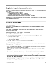
.... Strategy for replacing FRUs Before replacing parts: Make sure that the battery is fully charged and an ac power adapter is installed to replace a FRU but the replacement does not correct the problem, reinstall the original FRU before replacing any computer unless you have both a processor board and a system board. The BIOS and device drivers are available at http://www.lenovo.com/support. Go to all software fixes, drivers, and BIOS downloads are customer-installable. Chapter 2.
.... Strategy for replacing FRUs Before replacing parts: Make sure that the battery is fully charged and an ac power adapter is installed to replace a FRU but the replacement does not correct the problem, reinstall the original FRU before replacing any computer unless you have both a processor board and a system board. The BIOS and device drivers are available at http://www.lenovo.com/support. Go to all software fixes, drivers, and BIOS downloads are customer-installable. Chapter 2.
Hardware Maintenance Manual
Page 35
... physical or operating environment, or improper maintenance by the improper insertion of a PC Card or the installation of an incompatible card • Improper disc insertion or use new nylon-coated screws. • Be extremely careful during such write operations as cosmic radiation, electrostatic discharge, or software errors. Single failures can occur for repair costs if the computer damage was detected 6. Drives in which...
... physical or operating environment, or improper maintenance by the improper insertion of a PC Card or the installation of an incompatible card • Improper disc insertion or use new nylon-coated screws. • Be extremely careful during such write operations as cosmic radiation, electrostatic discharge, or software errors. Single failures can occur for repair costs if the computer damage was detected 6. Drives in which...
Hardware Maintenance Manual
Page 36
... button • Fuses blown by attachment of a nonsupported device • Forgotten computer password (making the computer unusable) • Sticky keys caused by spilling a liquid onto the keyboard • Use of an incorrect ac power adapter on laptop products The following symptoms might indicate damage caused by nonwarranted activities: • Missing parts might be a symptom of unauthorized service or modification. • If the spindle of a hard disk drive...
... button • Fuses blown by attachment of a nonsupported device • Forgotten computer password (making the computer unusable) • Sticky keys caused by spilling a liquid onto the keyboard • Use of an incorrect ac power adapter on laptop products The following symptoms might indicate damage caused by nonwarranted activities: • Missing parts might be a symptom of unauthorized service or modification. • If the spindle of a hard disk drive...
Hardware Maintenance Manual
Page 37
... the battery status indicator or icon does not turn on the operating system you are using, do the following : • Windows 7: Open the Power Manager program and click the Battery tab. • Windows 8: - Then reinstall the battery pack. To check your battery, depending on , replace the system board. Reinstall the battery pack. under this condition the battery pack can charge to room temperature. On the Windows operating system, press the recovery button...
... the battery status indicator or icon does not turn on the operating system you are using, do the following : • Windows 7: Open the Power Manager program and click the Battery tab. • Windows 8: - Then reinstall the battery pack. To check your battery, depending on , replace the system board. Reinstall the battery pack. under this condition the battery pack can charge to room temperature. On the Windows operating system, press the recovery button...
Hardware Maintenance Manual
Page 40
...; Press the Fn key. • Open the LCD cover. • Turn on the power button. 34 Hardware Maintenance Manual Note: If only a supervisor password is set , a prompt for it will not be displayed on the screen whenever the computer is powered off monitor" timer on . Supervisor password A supervisor password protects the system information stored in screen blank mode: • The LCD is powered off. • The hard disk drive is turned on the Windows 7 operating system expires. Attention...
...; Press the Fn key. • Open the LCD cover. • Turn on the power button. 34 Hardware Maintenance Manual Note: If only a supervisor password is set , a prompt for it will not be displayed on the screen whenever the computer is powered off monitor" timer on . Supervisor password A supervisor password protects the system information stored in screen blank mode: • The LCD is powered off. • The hard disk drive is turned on the Windows 7 operating system expires. Attention...
Hardware Maintenance Manual
Page 43
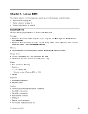
...) Display • Size: 14.0 inches (356 mm) • Resolution: - Chapter 5. LCD: 1366-by -1536 • Camera Keyboard • 6-row Lenovo keyboard • Recovery button Interface • Combo audio jack (stereo headphone or headset) • Two USB 2.0 connectors • Two USB 3.0 connectors • RJ45 Ethernet connector • HDMI port • External monitor connector • 4-in-1 digital media card reader slot © Copyright Lenovo 2012 37 Lenovo B490 This chapter presents the following product-specific service references...
...) Display • Size: 14.0 inches (356 mm) • Resolution: - Chapter 5. LCD: 1366-by -1536 • Camera Keyboard • 6-row Lenovo keyboard • Recovery button Interface • Combo audio jack (stereo headphone or headset) • Two USB 2.0 connectors • Two USB 3.0 connectors • RJ45 Ethernet connector • HDMI port • External monitor connector • 4-in-1 digital media card reader slot © Copyright Lenovo 2012 37 Lenovo B490 This chapter presents the following product-specific service references...
Hardware Maintenance Manual
Page 45
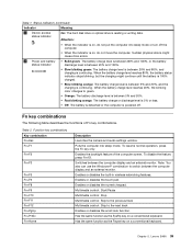
... 80% and 100%, or the battery status indicator discharge level is between 20% and 100%. • Slow blinking green: The battery charge level is between the computer display and an external monitor. Enables or disables the built-in wireless networking features. Has the same function as the SysRq key on a conventional keyboard. Table 2. Status indicators (continued) Indicator Meaning 3 Device access status indicator On: The hard disk drive or optical drive is continuing. Attention: •...
... 80% and 100%, or the battery status indicator discharge level is between 20% and 100%. • Slow blinking green: The battery charge level is between the computer display and an external monitor. Enables or disables the built-in wireless networking features. Has the same function as the SysRq key on a conventional keyboard. Table 2. Status indicators (continued) Indicator Meaning 3 Device access status indicator On: The hard disk drive or optical drive is continuing. Attention: •...
Hardware Maintenance Manual
Page 49
... discharge. For optional-service CRUs, you can find the manual for use the correct screw(s) as given in the drawings by removing any interconnecting cables. You might look differently from electrical outlets, remove the battery pack, and then disconnect any FRUs that all power cords from the illustrations in each FRU replacement section. When return is your Lenovo Limited Warranty documentation...
... discharge. For optional-service CRUs, you can find the manual for use the correct screw(s) as given in the drawings by removing any interconnecting cables. You might look differently from electrical outlets, remove the battery pack, and then disconnect any FRUs that all power cords from the illustrations in each FRU replacement section. When return is your Lenovo Limited Warranty documentation...
Hardware Maintenance Manual
Page 53
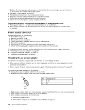
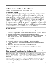
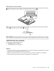
Removing and replacing a FRU 47 Chapter 7. Ensure that it is firmly installed in the slot and does not move easily. 1050 Hard disk drive assembly For access, remove these FRUs in order: • "1010 Battery pack" on page 44 • "1020 Bottom slot cover" on it if possible. • Never remove the drive while the computer is operating or is in SLOT-1 ( b : upper slot). The drive is sensitive to it...
Removing and replacing a FRU 47 Chapter 7. Ensure that it is firmly installed in the slot and does not move easily. 1050 Hard disk drive assembly For access, remove these FRUs in order: • "1010 Battery pack" on page 44 • "1020 Bottom slot cover" on it if possible. • Never remove the drive while the computer is operating or is in SLOT-1 ( b : upper slot). The drive is sensitive to it...
Hardware Maintenance Manual
Page 64
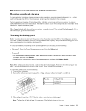
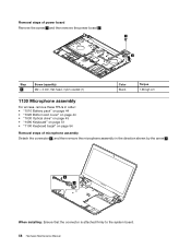
Removal steps of power board Remove the screw 1 and then remove the power board 2 . 1 2 Step 1 Screw (quantity) M2 × 3 mm, flat-head, nylon-coated (1) Color Black Torque 1.85 kgf-cm 1130 Microphone assembly For access, remove these FRUs in order: • "1010 Battery pack" on page 44 • "1020 Bottom slot cover" on page 44 • "1030 Optical drive" on page 45 • "1090 Keyboard" on page 51...
Removal steps of power board Remove the screw 1 and then remove the power board 2 . 1 2 Step 1 Screw (quantity) M2 × 3 mm, flat-head, nylon-coated (1) Color Black Torque 1.85 kgf-cm 1130 Microphone assembly For access, remove these FRUs in order: • "1010 Battery pack" on page 44 • "1020 Bottom slot cover" on page 44 • "1030 Optical drive" on page 45 • "1090 Keyboard" on page 51...
Hardware Maintenance Manual
Page 66
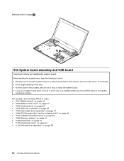
... on page 58 60 Hardware Maintenance Manual For access, remove these FRUs in order: • "1010 Battery pack" on page 44 • "1020 Bottom slot cover" on page 44 • "1030 Optical drive" on page 45 • "1040 Memory modules" on page 46 • "1050 Hard disk drive assembly" on page 47 • "1060 PCI Express Mini Card for handling the system board: When handling the system...
... on page 58 60 Hardware Maintenance Manual For access, remove these FRUs in order: • "1010 Battery pack" on page 44 • "1020 Bottom slot cover" on page 44 • "1030 Optical drive" on page 45 • "1040 Memory modules" on page 46 • "1050 Hard disk drive assembly" on page 47 • "1060 PCI Express Mini Card for handling the system board: When handling the system...
Hardware Maintenance Manual
Page 68
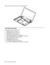
Remove the USB board as shown in the following illustration. 1160 Thermal module For access, remove these FRUs in order: • "1010 Battery pack" on page 44 • "1020 Bottom slot cover" on page 44 • "1030 Optical drive" on page 45 • "1040 Memory modules" on page 46 • "1050 Hard disk drive assembly" on page 47 • "1060 PCI Express Mini Card for wireless LAN" on page 49...
Remove the USB board as shown in the following illustration. 1160 Thermal module For access, remove these FRUs in order: • "1010 Battery pack" on page 44 • "1020 Bottom slot cover" on page 44 • "1030 Optical drive" on page 45 • "1040 Memory modules" on page 46 • "1050 Hard disk drive assembly" on page 47 • "1060 PCI Express Mini Card for wireless LAN" on page 49...
Hardware Maintenance Manual
Page 71
... in order: • "1010 Battery pack" on page 44 • "1020 Bottom slot cover" on page 44 • "1030 Optical drive" on page 45 • "1040 Memory modules" on page 46 • "1050 Hard disk drive assembly" on page 47 • "1060 PCI Express Mini Card for wireless LAN" on page 49 • "1070 mSATA solid state drive" on page 50 • "1080 Backup battery" on...
... in order: • "1010 Battery pack" on page 44 • "1020 Bottom slot cover" on page 44 • "1030 Optical drive" on page 45 • "1040 Memory modules" on page 46 • "1050 Hard disk drive assembly" on page 47 • "1060 PCI Express Mini Card for wireless LAN" on page 49 • "1070 mSATA solid state drive" on page 50 • "1080 Backup battery" on...
Hardware Maintenance Manual
Page 72
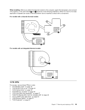
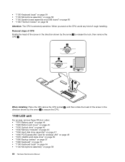
... the arrow 1 to secure the CPU. 1180 LCD unit For access, remove these FRUs in order: • "1010 Battery pack" on page 44 • "1020 Bottom slot cover" on page 44 • "1030 Optical drive" on page 45 • "1040 Memory modules" on page 46 • "1050 Hard disk drive assembly" on page 47 • "1060 PCI Express Mini Card for wireless LAN" on page 49 •...
... the arrow 1 to secure the CPU. 1180 LCD unit For access, remove these FRUs in order: • "1010 Battery pack" on page 44 • "1020 Bottom slot cover" on page 44 • "1030 Optical drive" on page 45 • "1040 Memory modules" on page 46 • "1050 Hard disk drive assembly" on page 47 • "1060 PCI Express Mini Card for wireless LAN" on page 49 •...
Hardware Maintenance Manual
Page 74
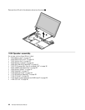
... the arrow 2 . 2 1190 Speaker assembly For access, remove these FRUs in order: • "1010 Battery pack" on page 44 • "1020 Bottom slot cover" on page 44 • "1030 Optical drive" on page 45 • "1040 Memory modules" on page 46 • "1050 Hard disk drive assembly" on page 47 • "1060 PCI Express Mini Card for wireless LAN" on page 49 • "1070 mSATA...
... the arrow 2 . 2 1190 Speaker assembly For access, remove these FRUs in order: • "1010 Battery pack" on page 44 • "1020 Bottom slot cover" on page 44 • "1030 Optical drive" on page 45 • "1040 Memory modules" on page 46 • "1050 Hard disk drive assembly" on page 47 • "1060 PCI Express Mini Card for wireless LAN" on page 49 • "1070 mSATA...
Hardware Maintenance Manual
Page 75
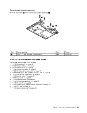
... (4) 1200 DC-in connector and base cover For access, remove these FRUs in order: • "1010 Battery pack" on page 44 • "1020 Bottom slot cover" on page 44 • "1030 Optical drive" on page 45 • "1040 Memory modules" on page 46 • "1050 Hard disk drive assembly" on page 47 • "1060 PCI Express Mini Card for wireless LAN" on page 49 • "1070...
... (4) 1200 DC-in connector and base cover For access, remove these FRUs in order: • "1010 Battery pack" on page 44 • "1020 Bottom slot cover" on page 44 • "1030 Optical drive" on page 45 • "1040 Memory modules" on page 46 • "1050 Hard disk drive assembly" on page 47 • "1060 PCI Express Mini Card for wireless LAN" on page 49 • "1070...
Hardware Maintenance Manual
Page 84
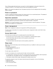
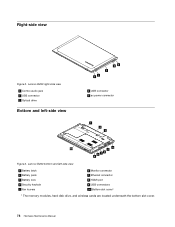
Lenovo B490 bottom and left -side view 45 3 12 4 USB connector 5 ac power connector 1 2 3 10 4 5 8 76 9 Figure 3. Right-side view Figure 2. Lenovo B490 right-side view 1 Combo audio jack 2 USB connector 3 Optical drive Bottom and left -side view 1 Battery latch 2 Battery pack 3 Battery lock 4 Security keyhole 5 Fan louvers 6 Monitor connector 7 Ethernet connector 8 HDMI port 9 USB connectors 10 Bottom slot cover1 1 The memory modules, hard disk drive, and wireless cards are located underneath the bottom slot cover. 78 Hardware Maintenance Manual
Lenovo B490 bottom and left -side view 45 3 12 4 USB connector 5 ac power connector 1 2 3 10 4 5 8 76 9 Figure 3. Right-side view Figure 2. Lenovo B490 right-side view 1 Combo audio jack 2 USB connector 3 Optical drive Bottom and left -side view 1 Battery latch 2 Battery pack 3 Battery lock 4 Security keyhole 5 Fan louvers 6 Monitor connector 7 Ethernet connector 8 HDMI port 9 USB connectors 10 Bottom slot cover1 1 The memory modules, hard disk drive, and wireless cards are located underneath the bottom slot cover. 78 Hardware Maintenance Manual
Hardware Maintenance Manual
Page 85
... and replacement instructions are shipped with the replacement CRU; Self-service CRUs: These CRUs unplug or are designated as optional-service CRUs. Once the access panel is removed, the specific CRU is not a CRU. and (2) you can request that is identified by an access panel that a Service Provider install the CRU according to find a list of CRUs include the ac power adapter, power cord, battery, and hard disk drive. Examples of these types...
... and replacement instructions are shipped with the replacement CRU; Self-service CRUs: These CRUs unplug or are designated as optional-service CRUs. Once the access panel is removed, the specific CRU is not a CRU. and (2) you can request that is identified by an access panel that a Service Provider install the CRU according to find a list of CRUs include the ac power adapter, power cord, battery, and hard disk drive. Examples of these types...


