Hardware Maintenance Manual
Page 3
... Handling devices that are sensitive to do first 29 Power system checkout 30 Checking the ac power adapter 30 Checking operational charging 31 Checking the battery pack 31 Chapter 4. Important service information 27 Strategy for replacing FRUs 27 Strategy for replacing a hard disk drive . . . 28 Important... 77 Right-side view 78 Bottom and left-side view 78 Chapter 9. Contents About this manual iii Chapter 1. Lenovo B490 37 Specifications 37 Status indicators 38 Fn key combinations 39 Chapter 6. Notices 93 Electronic emissions notices 94 Trademarks 94 © Copyright...
... Handling devices that are sensitive to do first 29 Power system checkout 30 Checking the ac power adapter 30 Checking operational charging 31 Checking the battery pack 31 Chapter 4. Important service information 27 Strategy for replacing FRUs 27 Strategy for replacing a hard disk drive . . . 28 Important... 77 Right-side view 78 Bottom and left-side view 78 Chapter 9. Contents About this manual iii Chapter 1. Lenovo B490 37 Specifications 37 Status indicators 38 Fn key combinations 39 Chapter 6. Notices 93 Electronic emissions notices 94 Trademarks 94 © Copyright...
Hardware Maintenance Manual
Page 9
...to electrostatic discharge (ESD.) ESD damage can continue without first correcting the problem. Safety information 3 Check exterior covers for cracked or bulging batteries. 5. Power off power. - Check inside the unit for : a. Protect against ESD damage by this inspection guide is to assist... specified in identifying potentially unsafe conditions. - c. Check for 0.1 ohm or less between objects. Check the power cord for any non-Lenovo alterations. 7. Switch off the computer. Notes: 1. Handling devices that the power-supply cover fasteners (screws or rivets) have not been...
...to electrostatic discharge (ESD.) ESD damage can continue without first correcting the problem. Safety information 3 Check exterior covers for cracked or bulging batteries. 5. Power off power. - Check inside the unit for : a. Protect against ESD damage by this inspection guide is to assist... specified in identifying potentially unsafe conditions. - c. Check for 0.1 ohm or less between objects. Check the power cord for any non-Lenovo alterations. 7. Switch off the computer. Notes: 1. Handling devices that the power-supply cover fasteners (screws or rivets) have not been...
Hardware Maintenance Manual
Page 10
... operator safety and correct system function. 2. Grounding requirements Electrical grounding of the electrical outlet can use coax or connector-outside shells on a double-insulated or battery-operated system, use have been certified (ISO 9000) as those listed below, to any frame ground, ground braid, or green-wire ground. - Safety notices (multilingual...
... operator safety and correct system function. 2. Grounding requirements Electrical grounding of the electrical outlet can use coax or connector-outside shells on a double-insulated or battery-operated system, use have been certified (ISO 9000) as those listed below, to any frame ground, ground braid, or green-wire ground. - Safety notices (multilingual...
Hardware Maintenance Manual
Page 33
...that board, and then replace the other one. © Copyright Lenovo 2012 27 An untrained person runs the risk of damaging the computer. • Before installing the latest utility, make sure that the battery is fully charged and an ac power adapter is installed to replace...servicing FRUs: • If you are instructed to the system board before replacing any computer unless you are instructed to http://www.lenovo.com/support. 2. Important service information This chapter presents the following important service information that all machine types supported by product category 3....
...that board, and then replace the other one. © Copyright Lenovo 2012 27 An untrained person runs the risk of damaging the computer. • Before installing the latest utility, make sure that the battery is fully charged and an ac power adapter is installed to replace...servicing FRUs: • If you are instructed to the system board before replacing any computer unless you are instructed to http://www.lenovo.com/support. 2. Important service information This chapter presents the following important service information that all machine types supported by product category 3....
Hardware Maintenance Manual
Page 36
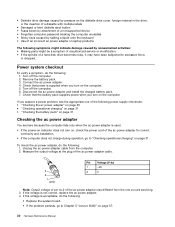
... does not charge during operation, go to Chapter 5 "Lenovo B490" on , check the power cord of a hard disk drive becomes noisy, it may different from the computer. 2. Power system checkout To verify a symptom, do the following : 1. Remove the battery pack. 3. Disconnect the ac power adapter and install the...supply checkouts: • "Checking the ac power adapter" on page 30 • "Checking operational charging" on page 31 • "Checking the battery pack" on page 31 Checking the ac power adapter You are servicing. 3. If the voltage is used. • If the power-on indicator ...
... does not charge during operation, go to Chapter 5 "Lenovo B490" on , check the power cord of a hard disk drive becomes noisy, it may different from the computer. 2. Power system checkout To verify a symptom, do the following : 1. Remove the battery pack. 3. Disconnect the ac power adapter and install the...supply checkouts: • "Checking the ac power adapter" on page 30 • "Checking operational charging" on page 31 • "Checking the battery pack" on page 31 Checking the ac power adapter You are servicing. 3. If the voltage is used. • If the power-on indicator ...
Hardware Maintenance Manual
Page 37
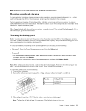
... even if the indicator does not turn on , replace the system board. Chapter 3. Reinstall the battery pack. Press Fn+Esc to launch the Lenovo Solution Center program, and then click Battery. - Power off the computer. 2. Perform operational charging. If it return to + 14 Ground ...3. On the Windows operating system, press the recovery button to launch the Lenovo Experience program, and then click Battery Health. To check the battery pack, do the following : 1. Checking the battery pack Battery charging does not start until the power meter shows that has less than ...
... even if the indicator does not turn on , replace the system board. Chapter 3. Reinstall the battery pack. Press Fn+Esc to launch the Lenovo Solution Center program, and then click Battery. - Power off the computer. 2. Perform operational charging. If it return to + 14 Ground ...3. On the Windows operating system, press the recovery button to launch the Lenovo Experience program, and then click Battery Health. To check the battery pack, do the following : 1. Checking the battery pack Battery charging does not start until the power meter shows that has less than ...
Hardware Maintenance Manual
Page 38
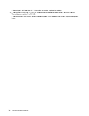
The resistance must be 4 to 30 K Ω. If the resistance is more than +11.0 V dc after recharging, replace the battery. 4. If the voltage is correct, replace the system board. 32 Hardware Maintenance Manual If the voltage is not correct, replace the battery pack. If the resistance is still less than +11.0 V dc, measure the resistance between battery terminals 5 and 7.
The resistance must be 4 to 30 K Ω. If the resistance is more than +11.0 V dc after recharging, replace the battery. 4. If the voltage is correct, replace the system board. 32 Hardware Maintenance Manual If the voltage is not correct, replace the battery pack. If the resistance is still less than +11.0 V dc, measure the resistance between battery terminals 5 and 7.
Hardware Maintenance Manual
Page 40
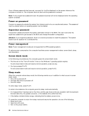
... any operation with the keyboard, the hard disk drive, the parallel connector, or the diskette drive within that time. • If the battery indicator blinks orange, indicating that the battery power is turned on. Note: If only a supervisor password is set, the password prompt will be started . The system board must be...
... any operation with the keyboard, the hard disk drive, the parallel connector, or the diskette drive within that time. • If the battery indicator blinks orange, indicating that the battery power is turned on. Note: If only a supervisor password is set, the password prompt will be started . The system board must be...
Hardware Maintenance Manual
Page 45
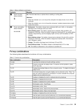
...less. • Off: The battery is detached or the computer is continuing. Puts the computer into sleep mode or turn off . To disable the feature, press Fn+F2. Enables or disables the built-in wireless networking features. Chapter 5. Lenovo B490 39 Sudden physical shock might continue... until the battery is 100% charged. • Slow blinking orange: The battery charge level is between 20% and 80%, and charging is powered off the computer. ...
...less. • Off: The battery is detached or the computer is continuing. Puts the computer into sleep mode or turn off . To disable the feature, press Fn+F2. Enables or disables the built-in wireless networking features. Chapter 5. Lenovo B490 39 Sudden physical shock might continue... until the battery is 100% charged. • Slow blinking orange: The battery charge level is between 20% and 80%, and charging is powered off the computer. ...
Hardware Maintenance Manual
Page 49
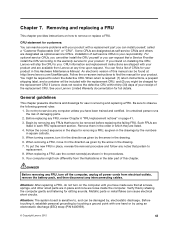
...any FRUs that all power cords from electrical outlets, remove the battery pack, and then disconnect any time upon request. Follow the correct sequence in the steps for the replacement CRU if Lenovo does not receive the defective CRU within thirty (30) days of...in each FRU replacement section. When replacing a FRU, use in this by using an electrostatic discharge (ESD) strap (P/N 6405959). © Copyright Lenovo 2012 43 Verify this Hardware Maintenance Manual. Attention: The system board is required: (1) return instructions, a prepaid shipping label, and a container ...
...any FRUs that all power cords from electrical outlets, remove the battery pack, and then disconnect any time upon request. Follow the correct sequence in the steps for the replacement CRU if Lenovo does not receive the defective CRU within thirty (30) days of...in each FRU replacement section. When replacing a FRU, use in this by using an electrostatic discharge (ESD) strap (P/N 6405959). © Copyright Lenovo 2012 43 Verify this Hardware Maintenance Manual. Attention: The system board is required: (1) return instructions, a prepaid shipping label, and a container ...
Hardware Maintenance Manual
Page 50
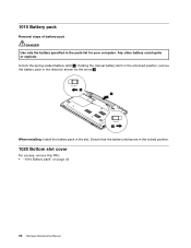
Ensure that the battery latches are in the parts list for your computer. 1010 Battery pack Removal steps of battery pack DANGER Use only the battery specified in the locked position. 1020 Bottom slot cover For access, remove this FRU: • "1010 Battery pack" on page 44 44 Hardware Maintenance Manual Unlock the spring-loaded battery latch 1 . Any other battery could ignite or explode. Holding the manual battery latch in the unlocked position, remove the battery pack in the direction shown by the arrow 2 . 1 2 2 When installing: Install the battery pack in the slot.
Ensure that the battery latches are in the parts list for your computer. 1010 Battery pack Removal steps of battery pack DANGER Use only the battery specified in the locked position. 1020 Bottom slot cover For access, remove this FRU: • "1010 Battery pack" on page 44 44 Hardware Maintenance Manual Unlock the spring-loaded battery latch 1 . Any other battery could ignite or explode. Holding the manual battery latch in the unlocked position, remove the battery pack in the direction shown by the arrow 2 . 1 2 2 When installing: Install the battery pack in the slot.
Hardware Maintenance Manual
Page 51
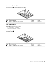
Removing and replacing a FRU 45 Removal steps of bottom slot cover Remove the screws 1 , and then remove the cover 2 . 1 1 2 2 Step 1 Screw (quantity) M2 × 3 mm, flat-head, nylon-coated (2) 1030 Optical drive For access, remove these FRUs in order: • "1010 Battery pack" on page 44 • "1020 Bottom slot cover" on page 44 Removal steps of optical drive Remove the screw 1 . 1 Color Black Torque 1.85 kgf-cm Step 1 Screw (quantity) M2 × 3 mm, flat-head, nylon-coated (1) Color Black Torque 1.85 kgf-cm Chapter 7.
Removing and replacing a FRU 45 Removal steps of bottom slot cover Remove the screws 1 , and then remove the cover 2 . 1 1 2 2 Step 1 Screw (quantity) M2 × 3 mm, flat-head, nylon-coated (2) 1030 Optical drive For access, remove these FRUs in order: • "1010 Battery pack" on page 44 • "1020 Bottom slot cover" on page 44 Removal steps of optical drive Remove the screw 1 . 1 Color Black Torque 1.85 kgf-cm Step 1 Screw (quantity) M2 × 3 mm, flat-head, nylon-coated (1) Color Black Torque 1.85 kgf-cm Chapter 7.
Hardware Maintenance Manual
Page 52
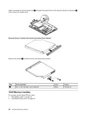
Step 1 Screw (quantity) M2 × 3 mm, flat-head, nylon-coated (2) 1040 Memory modules For access, remove these FRUs in the direction shown by the arrow 3 . Insert a screwdriver into the screw hole 2 and push the optical drive in order: • "1010 Battery pack" on page 44 • "1020 Bottom slot cover" on page 44 46 Hardware Maintenance Manual 1 2 Color Black Torque 1.85 kgf-cm Then remove the optical drive. 2 3 Removal steps of optical drive bezel and optical drive bracket Remove the screws 1 and then remove the optical drive bracket.
Step 1 Screw (quantity) M2 × 3 mm, flat-head, nylon-coated (2) 1040 Memory modules For access, remove these FRUs in the direction shown by the arrow 3 . Insert a screwdriver into the screw hole 2 and push the optical drive in order: • "1010 Battery pack" on page 44 • "1020 Bottom slot cover" on page 44 46 Hardware Maintenance Manual 1 2 Color Black Torque 1.85 kgf-cm Then remove the optical drive. 2 3 Removal steps of optical drive bezel and optical drive bracket Remove the screws 1 and then remove the optical drive bracket.
Hardware Maintenance Manual
Page 53
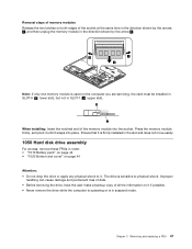
... memory module is used on the computer you are servicing, the card must be installed in SLOT-0 ( a : lower slot), but not in order: • "1010 Battery pack" on page 44 • "1020 Bottom slot cover" on it if possible. • Never remove the drive while the computer is operating or is...
... memory module is used on the computer you are servicing, the card must be installed in SLOT-0 ( a : lower slot), but not in order: • "1010 Battery pack" on page 44 • "1020 Bottom slot cover" on it if possible. • Never remove the drive while the computer is operating or is...
Hardware Maintenance Manual
Page 55
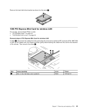
... disk drive bracket as shown by the arrow 2 . 2 1060 PCI Express Mini Card for wireless LAN For access, remove these FRUs in order: • "1010 Battery pack" on page 44 • "1020 Bottom slot cover" on page 44 Removal steps of PCI Express Mini Card for wireless LAN In steps 1 , disconnect...
... disk drive bracket as shown by the arrow 2 . 2 1060 PCI Express Mini Card for wireless LAN For access, remove these FRUs in order: • "1010 Battery pack" on page 44 • "1020 Bottom slot cover" on page 44 Removal steps of PCI Express Mini Card for wireless LAN In steps 1 , disconnect...
Hardware Maintenance Manual
Page 56
... (quantity) M2 × 3 mm, flat-head, nylon-coated (1) 50 Hardware Maintenance Manual Color Black Torque 1.85 kgf-cm The drive is in order: • "1010 Battery pack" on page 44 • "1020 Bottom slot cover" on page 44 Attention: • Do not drop the drive or apply any physical shock to...
... (quantity) M2 × 3 mm, flat-head, nylon-coated (1) 50 Hardware Maintenance Manual Color Black Torque 1.85 kgf-cm The drive is in order: • "1010 Battery pack" on page 44 • "1020 Bottom slot cover" on page 44 Attention: • Do not drop the drive or apply any physical shock to...
Hardware Maintenance Manual
Page 57
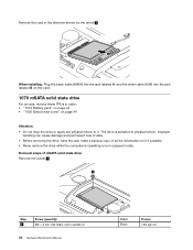
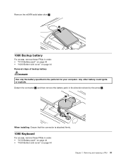
... Keyboard For access, remove these FRUs in order: • "1010 Battery pack" on page 44 • "1020 Bottom slot cover" on page 44 Removal steps of backup battery DANGER Use only the battery specified in order: • "1010 Battery pack" on page 44 • "1020 Bottom slot cover" on page... 44 Chapter 7. Removing and replacing a FRU 51 Any other battery could ignite or explode. Remove the mSATA solid state...
... Keyboard For access, remove these FRUs in order: • "1010 Battery pack" on page 44 • "1020 Bottom slot cover" on page 44 Removal steps of backup battery DANGER Use only the battery specified in order: • "1010 Battery pack" on page 44 • "1020 Bottom slot cover" on page... 44 Chapter 7. Removing and replacing a FRU 51 Any other battery could ignite or explode. Remove the mSATA solid state...
Hardware Maintenance Manual
Page 60
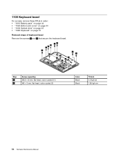
1100 Keyboard bezel For access, remove these FRUs in order: • "1010 Battery pack" on page 44 • "1020 Bottom slot cover" on page 44 • "1030 Optical drive" on page 45 • "1090 Keyboard" on page 51 Removal steps of keyboard bezel Remove the screws 1 and 2 that secure the keyboard bezel. 2 2 2 11 1 1 1 1 1 1 1 1 1 Step 1 2 Screw (quantity) M2.5 × 8 mm, flat-head, nylon-coated (11) M2 × 3 mm, flat-head, nylon-coated (3) Color Black Black Torque 4.0 kgf-cm 1.85 kgf-cm 54 Hardware Maintenance Manual
1100 Keyboard bezel For access, remove these FRUs in order: • "1010 Battery pack" on page 44 • "1020 Bottom slot cover" on page 44 • "1030 Optical drive" on page 45 • "1090 Keyboard" on page 51 Removal steps of keyboard bezel Remove the screws 1 and 2 that secure the keyboard bezel. 2 2 2 11 1 1 1 1 1 1 1 1 1 Step 1 2 Screw (quantity) M2.5 × 8 mm, flat-head, nylon-coated (11) M2 × 3 mm, flat-head, nylon-coated (3) Color Black Black Torque 4.0 kgf-cm 1.85 kgf-cm 54 Hardware Maintenance Manual
Hardware Maintenance Manual
Page 62
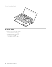
Remove the keyboard bezel. 10 1110 LED board For access, remove these FRUs in order: • "1010 Battery pack" on page 44 • "1020 Bottom slot cover" on page 44 • "1030 Optical drive" on page 45 • "1090 Keyboard" on page 51 • "1100 Keyboard bezel" on page 54 56 Hardware Maintenance Manual
Remove the keyboard bezel. 10 1110 LED board For access, remove these FRUs in order: • "1010 Battery pack" on page 44 • "1020 Bottom slot cover" on page 44 • "1030 Optical drive" on page 45 • "1090 Keyboard" on page 51 • "1100 Keyboard bezel" on page 54 56 Hardware Maintenance Manual
Hardware Maintenance Manual
Page 63
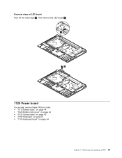
Then remove the LED board 2 . 1 2 1120 Power board For access, remove these FRUs in order: • "1010 Battery pack" on page 44 • "1020 Bottom slot cover" on page 44 • "1030 Optical drive" on page 45 • "1090 Keyboard" on page 51 • "1100 Keyboard bezel" on page 54 Chapter 7. Removal steps of LED board Peel off the mylar tape 1 . Removing and replacing a FRU 57
Then remove the LED board 2 . 1 2 1120 Power board For access, remove these FRUs in order: • "1010 Battery pack" on page 44 • "1020 Bottom slot cover" on page 44 • "1030 Optical drive" on page 45 • "1090 Keyboard" on page 51 • "1100 Keyboard bezel" on page 54 Chapter 7. Removal steps of LED board Peel off the mylar tape 1 . Removing and replacing a FRU 57


