Owner's Manual
Page 6
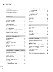
... 50 USB Entry Modes 52 Photo List 53 Music List 59 Movie List 62 DivX Registration Code 68 Deactivation 69 PICTURE CONTROL Picture Size (Aspect Ratio) Control 70 Picture Wizard 72 Energy Saving 74 Preset Picture Settings (Picture Mode 75 Manual Picture Adjustment - User Mode 76 Picture...Setup 23 VCR Setup 25 Other A/V Source Setup 26 USB Connection 26 Audio Out Connection 27 PC Setup 28 WATCHING TV / CHANNEL CONTROL Remote Control Functions 34 Turning On TV 36 Channel Selection 36 Volume Adjustment 36 Initial Setting 37 On-Screen Menus Selection 38 Quick Menu 39 ...
... 50 USB Entry Modes 52 Photo List 53 Music List 59 Movie List 62 DivX Registration Code 68 Deactivation 69 PICTURE CONTROL Picture Size (Aspect Ratio) Control 70 Picture Wizard 72 Energy Saving 74 Preset Picture Settings (Picture Mode 75 Manual Picture Adjustment - User Mode 76 Picture...Setup 23 VCR Setup 25 Other A/V Source Setup 26 USB Connection 26 Audio Out Connection 27 PC Setup 28 WATCHING TV / CHANNEL CONTROL Remote Control Functions 34 Turning On TV 36 Channel Selection 36 Volume Adjustment 36 Initial Setting 37 On-Screen Menus Selection 38 Quick Menu 39 ...
Owner's Manual
Page 9
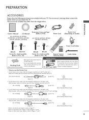
...the TV] [Figure 3] [Cross Section of Ferrite Core] 3. Wind the power cable on the ferrite core thrice. Use the ferrite core to P.13, 14) Remote Control, Batteries (AAA) Cable Holder * Wipe spots on model) x 4 x 3 x 4 x 3 1.5V 1.5V Power Cord Holder M4x26 M5x14.5 Screws for stand..., 42/50PT350, 42/50PT350C, 42/50PT250U, 50PV400, 50PV450, 50PV450C, 50PV550U) Protection Cover and Tape (Refer to P.14) (For 60PV250, 60PV400, 60PV450, 60PV450C, 60PV550U) Power Cord Ferrite Core (Depending on the exterior only with your TV. PREPARATION ACCESSORIES Ensure that the...
...the TV] [Figure 3] [Cross Section of Ferrite Core] 3. Wind the power cable on the ferrite core thrice. Use the ferrite core to P.13, 14) Remote Control, Batteries (AAA) Cable Holder * Wipe spots on model) x 4 x 3 x 4 x 3 1.5V 1.5V Power Cord Holder M4x26 M5x14.5 Screws for stand..., 42/50PT350, 42/50PT350C, 42/50PT250U, 50PV400, 50PV450, 50PV450C, 50PV550U) Protection Cover and Tape (Refer to P.14) (For 60PV250, 60PV400, 60PV450, 60PV450C, 60PV550U) Power Cord Ferrite Core (Depending on the exterior only with your TV. PREPARATION ACCESSORIES Ensure that the...
Owner's Manual
Page 10
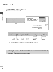
PREPARATION PREPARATION FRONT PANEL INFORMATION I Image shown may differ from fragments of glass, or the TV may fall. Remote Control Sensor HOME ENTER VOL CH POWER INPUT Button Button HOME Button ENTER Button VOLUME Buttons You can operate the buttons just by touching them lightly ...
PREPARATION PREPARATION FRONT PANEL INFORMATION I Image shown may differ from fragments of glass, or the TV may fall. Remote Control Sensor HOME ENTER VOL CH POWER INPUT Button Button HOME Button ENTER Button VOLUME Buttons You can operate the buttons just by touching them lightly ...
Owner's Manual
Page 12
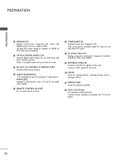
Uses a D-sub 15 pin cable (VGA cable). 5 REMOTE CONTROL IN PORT For a wired remote control. 6 COMPONENT IN Analog Connection. Supports standard definition video only (480i). 8 ANTENNA/CABLE IN Connect over-the air signals to this jack. 9 USB IN Used for ... AUDIO OUT Optical digital audio output for use with amps and home theater systems. Note: In standby mode, this port doesn't work. 3 RS-232C IN (CONTROL & SERVICE) PORT Used by third party devices. 4 AUDIO IN (RGB/DVI) 1/8" headphone jack for software updates. 11 Power Cord Socket For operation with AC power...
Uses a D-sub 15 pin cable (VGA cable). 5 REMOTE CONTROL IN PORT For a wired remote control. 6 COMPONENT IN Analog Connection. Supports standard definition video only (480i). 8 ANTENNA/CABLE IN Connect over-the air signals to this jack. 9 USB IN Used for ... AUDIO OUT Optical digital audio output for use with amps and home theater systems. Note: In standby mode, this port doesn't work. 3 RS-232C IN (CONTROL & SERVICE) PORT Used by third party devices. 4 AUDIO IN (RGB/DVI) 1/8" headphone jack for software updates. 11 Power Cord Socket For operation with AC power...
Owner's Manual
Page 20
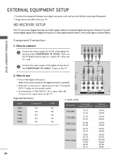
EXTERNAL EQUIPMENT SETUP I Select the Component1 input source on the TV using the INPUT button on the remote control. Y PB PR L R 2 Connect the audio output of the digital settop box to the COMPONENT IN VIDEO 1 jacks on the TV. 1 2 2. operation) I To ...prevent the equipment damage, never plug in any power cords until you do receive digital signals from your TV. O IN /DVI) REMOTE CONTROL IN AV IN 1 VIDEO /MONO AUDIO 2 L R 1 VIDEO AUDIO COMPONENT IN ANT CA Supported Resolutions Signal 480i 480p 720p 1080i 1080p Component Yes Yes Yes Yes...
EXTERNAL EQUIPMENT SETUP I Select the Component1 input source on the TV using the INPUT button on the remote control. Y PB PR L R 2 Connect the audio output of the digital settop box to the COMPONENT IN VIDEO 1 jacks on the TV. 1 2 2. operation) I To ...prevent the equipment damage, never plug in any power cords until you do receive digital signals from your TV. O IN /DVI) REMOTE CONTROL IN AV IN 1 VIDEO /MONO AUDIO 2 L R 1 VIDEO AUDIO COMPONENT IN ANT CA Supported Resolutions Signal 480i 480p 720p 1080i 1080p Component Yes Yes Yes Yes...
Owner's Manual
Page 21
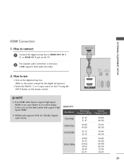
... TV using the INPUT button on the TV. 2 No separate audio connection is necessary. How to HDMI/DVI IN 1, 2, or HDMI IN 3 jack on the remote control. G HDMI mode supports PCM, AC-3(Dolby Digital) audio format. NOTE G If an HDMI cable doesn't support High Speed HDMI, it can cause flickers or no....94 29.97 21 EXTERNAL EQUIPMENT SETUP HDMI Connection 1. HDMI-DTV OUTPUT 1 OPTICAL DIGITAL AUDIO AUDIO OUT (RGB/DVI) 2 1 HDMI/DVI IN RS-232C IN (CONTROL & SERVICE) RGB IN(PC) !
... TV using the INPUT button on the TV. 2 No separate audio connection is necessary. How to HDMI/DVI IN 1, 2, or HDMI IN 3 jack on the remote control. G HDMI mode supports PCM, AC-3(Dolby Digital) audio format. NOTE G If an HDMI cable doesn't support High Speed HDMI, it can cause flickers or no....94 29.97 21 EXTERNAL EQUIPMENT SETUP HDMI Connection 1. HDMI-DTV OUTPUT 1 OPTICAL DIGITAL AUDIO AUDIO OUT (RGB/DVI) 2 1 HDMI/DVI IN RS-232C IN (CONTROL & SERVICE) RGB IN(PC) !
Owner's Manual
Page 22
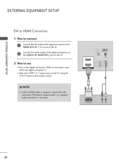
... IN R DIGITAL (RGB/DVI) CO AUDIO OUT RS-232C IN (CONTROL & SERVICE) RGB IN (PC) 2 2 1 1 HDMI/DVI IN 1 2 DVI-DTV OUTPUT R L 22 EXTERNAL EQUIPMENT SETUP EXTERNAL EQUIPMENT SETUP DVI to HDMI cable or adapter is necessary. How to the AUDIO IN (RGB/DVI) jack on the remote control. ! NOTE G A DVI to HDMI Connection 1.
... IN R DIGITAL (RGB/DVI) CO AUDIO OUT RS-232C IN (CONTROL & SERVICE) RGB IN (PC) 2 2 1 1 HDMI/DVI IN 1 2 DVI-DTV OUTPUT R L 22 EXTERNAL EQUIPMENT SETUP EXTERNAL EQUIPMENT SETUP DVI to HDMI cable or adapter is necessary. How to the AUDIO IN (RGB/DVI) jack on the remote control. ! NOTE G A DVI to HDMI Connection 1.
Owner's Manual
Page 23
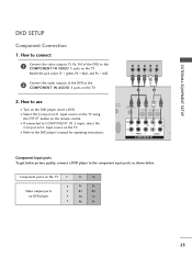
... /MONO AUDIO 2 L R 1 VIDEO AUDIO A COMPONENT IN Component Input ports To get better picture quality, connect a DVD player to the COMPONENT IN VIDEO 1 jacks on the remote control. How to connect 1 Connect the video outputs (Y, PB, PR) of the DVD to COMPONENT IN 2 input, select the Component2 input source on the DVD player...
... /MONO AUDIO 2 L R 1 VIDEO AUDIO A COMPONENT IN Component Input ports To get better picture quality, connect a DVD player to the COMPONENT IN VIDEO 1 jacks on the remote control. How to connect 1 Connect the video outputs (Y, PB, PR) of the DVD to COMPONENT IN 2 input, select the Component2 input source on the DVD player...
Owner's Manual
Page 24
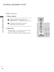
EXTERNAL EQUIPMENT SETUP EXTERNAL EQUIPMENT SETUP HDMI Connection 1. I Select the HDMI1, 2, or 3 input source on the TV using the INPUT button on the TV. 2 No separate audio connection is necessary. HDMI supports both audio and video. 2. HDMI-DTV OUTPUT 1 OPTICAL DIGITAL AUDIO AUDIO OUT (RGB/DV 2 1 HDMI/DVI IN RS-232C IN (CONTROL & SERVICE) RGB IN(PC) 24 How to connect 1 Connect the HDMI output of the DVD to the DVD player's manual for operating instructions. How to use I Refer to the HDMI/DVI IN 1, 2, or HDMI IN 3 jack on the remote control.
EXTERNAL EQUIPMENT SETUP EXTERNAL EQUIPMENT SETUP HDMI Connection 1. I Select the HDMI1, 2, or 3 input source on the TV using the INPUT button on the TV. 2 No separate audio connection is necessary. HDMI supports both audio and video. 2. HDMI-DTV OUTPUT 1 OPTICAL DIGITAL AUDIO AUDIO OUT (RGB/DV 2 1 HDMI/DVI IN RS-232C IN (CONTROL & SERVICE) RGB IN(PC) 24 How to connect 1 Connect the HDMI output of the DVD to the DVD player's manual for operating instructions. How to use I Refer to the HDMI/DVI IN 1, 2, or HDMI IN 3 jack on the remote control.
Owner's Manual
Page 25
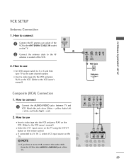
... AUDIO L/MONO jack of the TV. (PC) ANT IN S-VIDEO VIDEO L R ANT OUT OUTPUT SWITCH 1 UDIO B/DVI) REMOTE CONTROL IN AV IN 1 VIDEO /MONO AUDIO 2 L R 1 25 How to the ANTENNA/CABLE IN socket on the remote control. NOTE G If you have a mono VCR, connect the audio cable from the VCR to the RF antenna...
... AUDIO L/MONO jack of the TV. (PC) ANT IN S-VIDEO VIDEO L R ANT OUT OUTPUT SWITCH 1 UDIO B/DVI) REMOTE CONTROL IN AV IN 1 VIDEO /MONO AUDIO 2 L R 1 25 How to the ANTENNA/CABLE IN socket on the remote control. NOTE G If you have a mono VCR, connect the audio cable from the VCR to the RF antenna...
Owner's Manual
Page 26
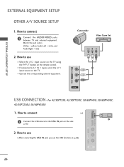
... = yellow, Audio Left = white, and Audio Right = red) 2. I N jack on the side of TV. 2. How to AV IN 1 input, select the A V 1 input source on the remote control. I Select the A V 2 input source on the TV using the INPUT button on the TV. How to use I After connecting the USB I N jack, you use I If...
... = yellow, Audio Left = white, and Audio Right = red) 2. I N jack on the side of TV. 2. How to AV IN 1 input, select the A V 1 input source on the remote control. I Select the A V 2 input source on the TV using the INPUT button on the TV. How to use I After connecting the USB I N jack, you use I If...
Owner's Manual
Page 28
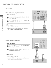
... EXTERNAL EQUIPMENT SETUP PC SETUP VGA (D-Sub 15 pin) Connection 1. I Select the RGB-PC input source on the TV using the INPUT button on the remote control. How to connect 1 Connect the DVI output of the PC to the RGB IN (P C) jack on the PC and the TV. How to connect 1 ...to use I Turn on the TV. 2 Connect the PC audio output to HDMI Connection 1. OPTICAL DIGITAL AUDIO OUT AUDIO IN (RGB/DVI) REMOTE CONTROL IN VIDEO 2 2 1 VIDEO COMPONEN 1 RS-232C IN (CONTROL & SERVICE) RGB IN (PC) 2 1 AUDIO RGB OUTPUT DVI to the AUDIO IN (RGB/DVI) jack on the PC and the TV...
... EXTERNAL EQUIPMENT SETUP PC SETUP VGA (D-Sub 15 pin) Connection 1. I Select the RGB-PC input source on the TV using the INPUT button on the remote control. How to connect 1 Connect the DVI output of the PC to the RGB IN (P C) jack on the PC and the TV. How to connect 1 ...to use I Turn on the TV. 2 Connect the PC audio output to HDMI Connection 1. OPTICAL DIGITAL AUDIO OUT AUDIO IN (RGB/DVI) REMOTE CONTROL IN VIDEO 2 2 1 VIDEO COMPONEN 1 RS-232C IN (CONTROL & SERVICE) RGB IN (PC) 2 1 AUDIO RGB OUTPUT DVI to the AUDIO IN (RGB/DVI) jack on the PC and the TV...
Owner's Manual
Page 34
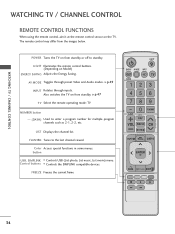
WATCHING TV / CHANNEL CONTROL WATCHING TV / CHANNEL CONTROL REMOTE CONTROL FUNCTIONS When using the remote control, aim it at the remote control sensor on Model) ENERGY SAVING Adjusts the Energy Saving. POWER Turns the TV on from standby. Color Access special ... LIST Displays the channel list. FLASHBK Tunes to the last channel viewed. FREEZE Freezes the current frame. LIGHT Illuminates the remote control buttons. (Depending on the TV. The remote control may differ from standby or off to enter a program number for multiple program channels such as 2-1, 2-2, etc. AV ...
WATCHING TV / CHANNEL CONTROL WATCHING TV / CHANNEL CONTROL REMOTE CONTROL FUNCTIONS When using the remote control, aim it at the remote control sensor on Model) ENERGY SAVING Adjusts the Energy Saving. POWER Turns the TV on from standby. Color Access special ... LIST Displays the channel list. FLASHBK Tunes to the last channel viewed. FREEZE Freezes the current frame. LIGHT Illuminates the remote control buttons. (Depending on the TV. The remote control may differ from standby or off to enter a program number for multiple program channels such as 2-1, 2-2, etc. AV ...
Owner's Manual
Page 36
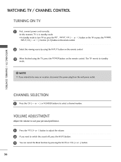
...G If you want to switch the sound off, press the MUTE button. 3 You can cancel the Mute function by using the INPUT button on the remote control. 3 When finished using the TV, press the POWER button on vacation, disconnect the power plug from the wall power outlet. VOLUME ADJUSTMENT Adjust the volume... to turn TV on, press the , INPUT, CH ( or ) button on the TV or press the POWER, INPUT, CH( or ), Number (0~9) button on the remote control. 2 Select the viewing source by pressing the MUTE or VOL (+ or -) button. 36 CHANNEL SELECTION 1 Press the CH ( or ) or NUMBER buttons to standby mode...
...G If you want to switch the sound off, press the MUTE button. 3 You can cancel the Mute function by using the INPUT button on the remote control. 3 When finished using the TV, press the POWER button on vacation, disconnect the power plug from the wall power outlet. VOLUME ADJUSTMENT Adjust the volume... to turn TV on, press the , INPUT, CH ( or ) button on the TV or press the POWER, INPUT, CH( or ), Number (0~9) button on the remote control. 2 Select the viewing source by pressing the MUTE or VOL (+ or -) button. 36 CHANNEL SELECTION 1 Press the CH ( or ) or NUMBER buttons to standby mode...
Owner's Manual
Page 50
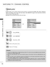
...Normal : 1 : Home Use 1 Home Select OPTION. 2 ENTER Select SIMPLINK. 3 ENTER Select O n or O f f. 4 BACK Return to the DIGITAL AUDIO IN terminal on the remote control, the SIMPLINK device will stop. NOTE G Connect the HDMI/DVI IN or HDMI IN terminal of the SIMPLINK device with HDMI cable without additional cables...the previous menu. SIMPLINK can be turned on the back of the SIMPLINK device with an OPTICAL cable. 50 WATCHING TV / CHANNEL CONTROL Simplink allows you to the home theater speakers and the TV speakers are fully supported. G When you select a device with home theater...
...Normal : 1 : Home Use 1 Home Select OPTION. 2 ENTER Select SIMPLINK. 3 ENTER Select O n or O f f. 4 BACK Return to the DIGITAL AUDIO IN terminal on the remote control, the SIMPLINK device will stop. NOTE G Connect the HDMI/DVI IN or HDMI IN terminal of the SIMPLINK device with HDMI cable without additional cables...the previous menu. SIMPLINK can be turned on the back of the SIMPLINK device with an OPTICAL cable. 50 WATCHING TV / CHANNEL CONTROL Simplink allows you to the home theater speakers and the TV speakers are fully supported. G When you select a device with home theater...

Owner's Manual
Page 53
... pages. 2 4 Total number of marked photo files. 5 Usable USB memory. 1 6 Corresponding buttons on your model may be slightly different. The On Screen Display on the remote control. USB PHOTO LIST You can play JPG files only.
... pages. 2 4 Total number of marked photo files. 5 Usable USB memory. 1 6 Corresponding buttons on your model may be slightly different. The On Screen Display on the remote control. USB PHOTO LIST You can play JPG files only.
Owner's Manual
Page 59
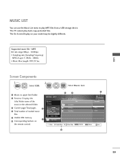
This TV cannot play MP3 files from a USB storage device. The On Screen Display on the remote control. Screen Components 1 Home Select U S B. 2 ENTER ENTER Select Music List. 1 Moves to play back copy-protected files. MUSIC LIST MP3 Arirang 3 4 Page 1/1 No Marked Title Up ...
This TV cannot play MP3 files from a USB storage device. The On Screen Display on the remote control. Screen Components 1 Home Select U S B. 2 ENTER ENTER Select Music List. 1 Moves to play back copy-protected files. MUSIC LIST MP3 Arirang 3 4 Page 1/1 No Marked Title Up ...
Owner's Manual
Page 63
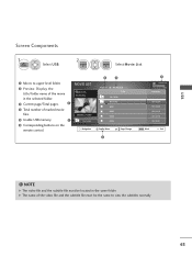
... must be the same to upper level folder. 2 Preview: Display the title/folder name of marked movie files. 5 Usable USB memory. 1 6 Corresponding buttons on the remote control. USB Screen Components 1 Home Select U S B. 2 ENTER ENTER Select Mo v i e Li s t. 1 Moves to view the subtitles normally 63 MOVIE LIST DriveA Butterfly 640x480, 707MB Up Folder...
... must be the same to upper level folder. 2 Preview: Display the title/folder name of marked movie files. 5 Usable USB memory. 1 6 Corresponding buttons on the remote control. USB Screen Components 1 Home Select U S B. 2 ENTER ENTER Select Mo v i e Li s t. 1 Moves to view the subtitles normally 63 MOVIE LIST DriveA Butterfly 640x480, 707MB Up Folder...

Owner's Manual
Page 65
... to move to speed up GG-> GGG -> GGGG -> GGGGG -> GGGGGG. repeatedly press the F F(GG) button to normal playback. ! I Still screen is displayed. USB Using the remote control You can be viewed on the screen. I When using the or buttons during playback a cursor indicating the position can adjust various method during movie play...
... to move to speed up GG-> GGG -> GGGG -> GGGGG -> GGGGGG. repeatedly press the F F(GG) button to normal playback. ! I Still screen is displayed. USB Using the remote control You can be viewed on the screen. I When using the or buttons during playback a cursor indicating the position can adjust various method during movie play...
Owner's Manual
Page 70
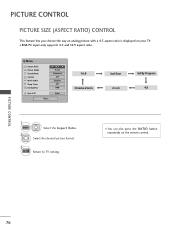
I You can also press the RATIO button repeatedly on your TV. PICTURE CONTROL 70 Select the desired picture format. 3 EXIT Return to TV viewing. I RGB-PC input only supports 4:3 and 16:9 aspect ratio. Q.Menu Aspect Ratio Picture Mode ...:9 G Vivid Standard Off English Off Add Eject USB Eject Close 16:9 Cinema Zoom Just Scan Zoom Set By Program 4:3 1 Q.MENU 2 Select the Aspect Ratio. PICTURE CONTROL PICTURE SIZE (ASPECT RATIO) CONTROL This feature lets you choose the way an analog picture with a 4:3 aspect ratio is displayed on the remote control.
I You can also press the RATIO button repeatedly on your TV. PICTURE CONTROL 70 Select the desired picture format. 3 EXIT Return to TV viewing. I RGB-PC input only supports 4:3 and 16:9 aspect ratio. Q.Menu Aspect Ratio Picture Mode ...:9 G Vivid Standard Off English Off Add Eject USB Eject Close 16:9 Cinema Zoom Just Scan Zoom Set By Program 4:3 1 Q.MENU 2 Select the Aspect Ratio. PICTURE CONTROL PICTURE SIZE (ASPECT RATIO) CONTROL This feature lets you choose the way an analog picture with a 4:3 aspect ratio is displayed on the remote control.

