Owner's Manual
Page 3
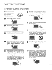
..., heat registers, stoves, or other . Servicing is required when the apparatus has been damaged in accordance with the manufacturer's instructions. 8 Use only with the cart, stand, tripod, bracket, or table specified by the manufacturer, or sold with one wider than the other apparatus (including amplifiers)that produce heat. 9 Unplug this apparatus...
..., heat registers, stoves, or other . Servicing is required when the apparatus has been damaged in accordance with the manufacturer's instructions. 8 Use only with the cart, stand, tripod, bracket, or table specified by the manufacturer, or sold with one wider than the other apparatus (including amplifiers)that produce heat. 9 Unplug this apparatus...
Owner's Manual
Page 6
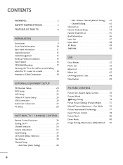
... VESA Wall Mounting 17 Securing the TV to the wall to prevent falling when the TV is used on a stand 18 Antenna or Cable Connection 19 EXTERNAL EQUIPMENT SETUP HD Receiver Setup 20 DVD Setup 23 VCR Setup 25 Other A/V Source Setup 26 USB Connection ...
... VESA Wall Mounting 17 Securing the TV to the wall to prevent falling when the TV is used on a stand 18 Antenna or Cable Connection 19 EXTERNAL EQUIPMENT SETUP HD Receiver Setup 20 DVD Setup 23 VCR Setup 25 Other A/V Source Setup 26 USB Connection ...
Owner's Manual
Page 9
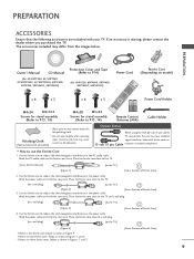
...50PT200, 42/50PT350, 42/50PT350C, 42/50PT250U, 50PV400, 50PV450, 50PV450C, 50PV550U) Protection Cover and Tape (Refer to P.14) (For 60PV250, 60PV400, 60PV450, 60PV450C, 60PV550U) Power Cord Ferrite Core (Depending on model) x 4 x 3 x 4 x 3 1.5V 1.5V Power Cord Holder M4x26 M5x14....5 Screws for stand assembly (Refer to P.13, 14) M4x28 M5x24 Screws for stand assembly (Refer to the TV] [Figure 4] - Place the ferrite core close to a wall plug. [to a wall plug] [to P....
...50PT200, 42/50PT350, 42/50PT350C, 42/50PT250U, 50PV400, 50PV450, 50PV450C, 50PV550U) Protection Cover and Tape (Refer to P.14) (For 60PV250, 60PV400, 60PV450, 60PV450C, 60PV550U) Power Cord Ferrite Core (Depending on model) x 4 x 3 x 4 x 3 1.5V 1.5V Power Cord Holder M4x26 M5x14....5 Screws for stand assembly (Refer to P.13, 14) M4x28 M5x24 Screws for stand assembly (Refer to the TV] [Figure 4] - Place the ferrite core close to a wall plug. [to a wall plug] [to P....
Owner's Manual
Page 10
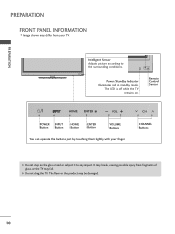
... buttons just by touching them lightly with your TV. G Do not drag the TV. The LED is off while the TV remains on the glass stand or subject it to the surrounding conditions. CHANNEL ENTER Buttons G Do not step on . It may break, causing possible injury from your finger. PREPARATION PREPARATION...
... buttons just by touching them lightly with your TV. G Do not drag the TV. The LED is off while the TV remains on the glass stand or subject it to the surrounding conditions. CHANNEL ENTER Buttons G Do not step on . It may break, causing possible injury from your finger. PREPARATION PREPARATION...
Owner's Manual
Page 13
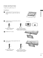
... 4 Fix the 4 screws securely using the holes in the back of the TV. PREPARATION STAND INSTRUCTION I Image shown may differ from damage. 2 Assemble the parts of the Stand Body with the Stand Base of the TV. x 4 M4x28 (For 60PV250, 60PV400, 60PV450, 60PV450C, 60PV550U) x 4 M4x26 (For 42/50PT200, 42/50PT350, 42/50PT350C, 42/50PT250U, 50PV400...
... 4 Fix the 4 screws securely using the holes in the back of the TV. PREPARATION STAND INSTRUCTION I Image shown may differ from damage. 2 Assemble the parts of the Stand Body with the Stand Base of the TV. x 4 M4x28 (For 60PV250, 60PV400, 60PV450, 60PV450C, 60PV550U) x 4 M4x26 (For 42/50PT200, 42/50PT350, 42/50PT350C, 42/50PT250U, 50PV400...
Owner's Manual
Page 14
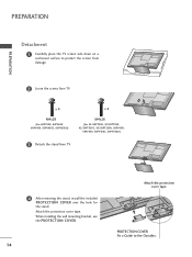
... 1 Carefully place the TV screen side down on a cushioned surface to the Outsides. x 4 M4x28 (For 60PV250, 60PV400, 60PV450, 60PV450C, 60PV550U) x 4 M4x26 (For 42/50PT200, 42/50PT350, 42/50PT350C, 42/50PT250U, 50PV400, 50PV450, 50PV450C, 50PV550U) 3 Detach the stand from TV. When installing the wall mounting bracket, use the PROTECTION COVER. 14 Attach the...
... 1 Carefully place the TV screen side down on a cushioned surface to the Outsides. x 4 M4x28 (For 60PV250, 60PV400, 60PV450, 60PV450C, 60PV550U) x 4 M4x26 (For 42/50PT200, 42/50PT350, 42/50PT350C, 42/50PT250U, 50PV400, 50PV450, 50PV450C, 50PV550U) 3 Detach the stand from TV. When installing the wall mounting bracket, use the PROTECTION COVER. 14 Attach the...
Owner's Manual
Page 16
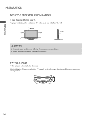
For proper ventilation, allow a clearance of heat source. G Do not mount near or above any type of 4 inches on all models. PREPARATION PREPARATION DESKTOP PEDESTAL INSTALLATION I This feature is not available for all four sides from your viewing position. 16 SWIVEL STAND I Image shown may differ from the wall. 4 inches 4 inches 4 inches 4 inches CAUTION G Ensure adequate ventilation by 20 degrees to the left or right direction by following the clearance recommendations. After installing the TV, you can adjust the TV manually to suit your TV.
For proper ventilation, allow a clearance of heat source. G Do not mount near or above any type of 4 inches on all models. PREPARATION PREPARATION DESKTOP PEDESTAL INSTALLATION I This feature is not available for all four sides from your viewing position. 16 SWIVEL STAND I Image shown may differ from the wall. 4 inches 4 inches 4 inches 4 inches CAUTION G Ensure adequate ventilation by 20 degrees to the left or right direction by following the clearance recommendations. After installing the TV, you can adjust the TV manually to suit your TV.
Owner's Manual
Page 18
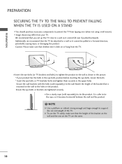
... the TV from tipping over if pushed backwards. PREPARATION PREPARATION SECURING THE TV TO THE WALL TO PREVENT FALLING WHEN THE TV IS USED ON A STAND I Image shown may differ from your product has the bolts in the eye-bolts position before inserting the eye-bolts, loosen the bolts. * Insert the...
... the TV from tipping over if pushed backwards. PREPARATION PREPARATION SECURING THE TV TO THE WALL TO PREVENT FALLING WHEN THE TV IS USED ON A STAND I Image shown may differ from your product has the bolts in the eye-bolts position before inserting the eye-bolts, loosen the bolts. * Insert the...
Owner's Manual
Page 114
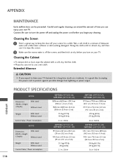
... damage from lightning or power surges. 114 APPENDIX PRODUCT SPECIFICATIONS MODEL Dimensions (Width x Height x Depth) With stand Without stand Weight With stand Without stand Current Value / Power consumption MODEL Dimensions (Width x Height x Depth) With stand Without stand Weight With stand Without stand Current Value / Power consumption 42PT200 (42PT200-UB) 42PT250U (42PT250U-UA) 987.6 mm x 662.8 mm x 230.5 mm...
... damage from lightning or power surges. 114 APPENDIX PRODUCT SPECIFICATIONS MODEL Dimensions (Width x Height x Depth) With stand Without stand Weight With stand Without stand Current Value / Power consumption MODEL Dimensions (Width x Height x Depth) With stand Without stand Weight With stand Without stand Current Value / Power consumption 42PT200 (42PT200-UB) 42PT250U (42PT250U-UA) 987.6 mm x 662.8 mm x 230.5 mm...
Owner's Manual
Page 115
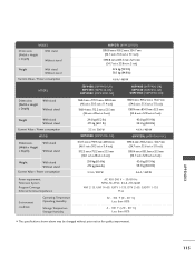
... (Width x Height x Depth) With stand Without stand Weight With stand Without stand Current Value / Power consumption MODEL Dimensions (Width x Height x Depth) With stand Without stand Weight With stand Without stand Current Value / Power consumption Power requirement Television System Program Coverage External Antenna Impedance Environment condition Operating Temperature Operating Humidity Storage Temperature Storage Humidity 60PV250 (60PV250-UB) 1390.8 mm x 905.2 mm...
... (Width x Height x Depth) With stand Without stand Weight With stand Without stand Current Value / Power consumption MODEL Dimensions (Width x Height x Depth) With stand Without stand Weight With stand Without stand Current Value / Power consumption Power requirement Television System Program Coverage External Antenna Impedance Environment condition Operating Temperature Operating Humidity Storage Temperature Storage Humidity 60PV250 (60PV250-UB) 1390.8 mm x 905.2 mm...


