Owner's Manual
Page 2
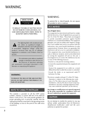
...to radio communications. Any changes or modifications not expressly approved by turning the equipment off and on a circuit different from LG Electronics. CAUTION Do not attempt to modify this product 2 Consult the dealer or an experienced radio/TV technician for proper ... installation. Unauthorized modification could void the user's authority to which can radiate radio frequency energy and, if not installed and used in accordance with the limits for compliance could void the user's authority to provide reasonable protection against harmful interference in a particular...
...to radio communications. Any changes or modifications not expressly approved by turning the equipment off and on a circuit different from LG Electronics. CAUTION Do not attempt to modify this product 2 Consult the dealer or an experienced radio/TV technician for proper ... installation. Unauthorized modification could void the user's authority to which can radiate radio frequency energy and, if not installed and used in accordance with the limits for compliance could void the user's authority to provide reasonable protection against harmful interference in a particular...
Owner's Manual
Page 3
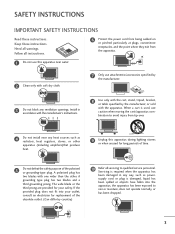
... Do not install near water. 2 Clean only with soft dry cloth. 7 Only use caution when moving the cart/apparatus com- Install in any ventilation openings. supply cord or plug is used, use attachments/accessories specified by country) 10 Refer all servicing to rain or moisture, does not...or objects have fallen into your safety. Servicing is required when the apparatus has been damaged in accordance with the manufacturer's instructions. 8 Use only with the cart, stand, tripod, bracket, or table specified by the manufacturer, or sold with one wider than the other apparatus...
... Do not install near water. 2 Clean only with soft dry cloth. 7 Only use caution when moving the cart/apparatus com- Install in any ventilation openings. supply cord or plug is used, use attachments/accessories specified by country) 10 Refer all servicing to rain or moisture, does not...or objects have fallen into your safety. Servicing is required when the apparatus has been damaged in accordance with the manufacturer's instructions. 8 Use only with the cart, stand, tripod, bracket, or table specified by the manufacturer, or sold with one wider than the other apparatus...
Owner's Manual
Page 4
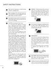
... could result in fire or electric shock. on the back of your appliance, and if its appearance indicates damage or deterioration, unplug it, discontinue use a damaged or loose power cord. If grounding methods are dangerous. Check the specification page of fire or electrical shock, do grasp the plug when... power cord to dripping or splashing and do not drop onto the screen with an exact replacement part by an authorized servicer. Do not use of these conditions could result in electric shock or fire. Do not install this owner's manual to fall into the product, and do ...
... could result in fire or electric shock. on the back of your appliance, and if its appearance indicates damage or deterioration, unplug it, discontinue use a damaged or loose power cord. If grounding methods are dangerous. Check the specification page of fire or electrical shock, do grasp the plug when... power cord to dripping or splashing and do not drop onto the screen with an exact replacement part by an authorized servicer. Do not use of these conditions could result in electric shock or fire. Do not install this owner's manual to fall into the product, and do ...
Owner's Manual
Page 6
... 15 Desktop Pedestal Installation 16 Swivel Stand 16 VESA Wall Mounting 17 Securing the TV to the wall to prevent falling when the TV is used on a stand 18 Antenna or Cable Connection 19 EXTERNAL EQUIPMENT SETUP HD Receiver Setup 20 DVD Setup 23 VCR Setup 25 Other A/V Source Setup 26...
... 15 Desktop Pedestal Installation 16 Swivel Stand 16 VESA Wall Mounting 17 Securing the TV to the wall to prevent falling when the TV is used on a stand 18 Antenna or Cable Connection 19 EXTERNAL EQUIPMENT SETUP HD Receiver Setup 20 DVD Setup 23 VCR Setup 25 Other A/V Source Setup 26...
Owner's Manual
Page 8
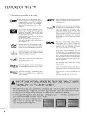
...are trademarks or registered trademarks of HDMI Licensing LLC." It includes Cinema, Sports, and Game Modes. Using a sophisticated algorithm, the LG processes picture quality elements including brightness, contrast, color, sharpness and white balance. The result is not... or more detailed picture. High-definition television. High-resolution digital television broadcast and playback system composed of ambient light, LG's "Intelligent Sensor" uses 4,096 sensing steps to help keep dialogue audible when background noise swells. Detailed calibration requires a licensed technician. View ...
...are trademarks or registered trademarks of HDMI Licensing LLC." It includes Cinema, Sports, and Game Modes. Using a sophisticated algorithm, the LG processes picture quality elements including brightness, contrast, color, sharpness and white balance. The result is not... or more detailed picture. High-definition television. High-resolution digital television broadcast and playback system composed of ambient light, LG's "Intelligent Sensor" uses 4,096 sensing steps to help keep dialogue audible when background noise swells. Detailed calibration requires a licensed technician. View ...
Owner's Manual
Page 9
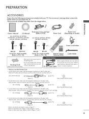
...Owner's Manual CD Manual (For 42/50PT200, 42/50PT350, 42/50PT350C, 42/50PT250U, 50PV400, 50PV450, 50PV450C, 50PV550U) Protection Cover and Tape (Refer to P.14) (For 60PV250, 60PV400, 60PV450, 60PV450C, 60PV550U) Power Cord Ferrite Core (Depending on model) x 4 x 3 x 4 x 3 1.5V 1.5V Power Cord Holder M4x26 M5x14.5 ... - Place the ferrite core close to a wall plug. [to a wall plug] [to D-sub 15 pin Cable maintain standards compliance. Use the ferrite core to reduce the electromagnetic interference in the PC audio cable. If an accessory is one ferrite core, follow as shown in ...
...Owner's Manual CD Manual (For 42/50PT200, 42/50PT350, 42/50PT350C, 42/50PT250U, 50PV400, 50PV450, 50PV450C, 50PV550U) Protection Cover and Tape (Refer to P.14) (For 60PV250, 60PV400, 60PV450, 60PV450C, 60PV550U) Power Cord Ferrite Core (Depending on model) x 4 x 3 x 4 x 3 1.5V 1.5V Power Cord Holder M4x26 M5x14.5 ... - Place the ferrite core close to a wall plug. [to a wall plug] [to D-sub 15 pin Cable maintain standards compliance. Use the ferrite core to reduce the electromagnetic interference in the PC audio cable. If an accessory is one ferrite core, follow as shown in ...
Owner's Manual
Page 12
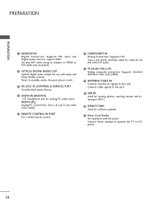
...video and Digital audio. RGB IN (PC) Analog PC Connection. Connect cable signals to this port doesn't work. 3 RS-232C IN (CONTROL & SERVICE) PORT Used by third party devices. 4 AUDIO IN (RGB/DVI) 1/8" headphone jack for audio. 7 AV (Audio/Video) IN Analog composite connection. Doesn't support 480i.... Caution: Never attempt to MP3s. 10 SERVICE ONLY Used for software updates. 11 Power Cord Socket For operation with amps and home theater systems. Note: In standby mode, this jack. 9 USB IN...
...video and Digital audio. RGB IN (PC) Analog PC Connection. Connect cable signals to this port doesn't work. 3 RS-232C IN (CONTROL & SERVICE) PORT Used by third party devices. 4 AUDIO IN (RGB/DVI) 1/8" headphone jack for audio. 7 AV (Audio/Video) IN Analog composite connection. Doesn't support 480i.... Caution: Never attempt to MP3s. 10 SERVICE ONLY Used for software updates. 11 Power Cord Socket For operation with amps and home theater systems. Note: In standby mode, this jack. 9 USB IN...
Owner's Manual
Page 13
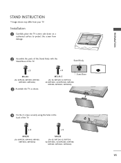
...(For 42/50PT200, 42/50PT350, 42/50PT350C, 42/50PT250U, 50PV400, 50PV450, 50PV450C, 50PV550U) Stand Base 4 Fix the 4 screws securely using the holes in the back of the TV. PREPARATION STAND INSTRUCTION I Image shown may differ from damage. 2 Assemble the parts of the ...Stand Body with the Stand Base of the TV. Stand Body x 3 M5x24 (For 60PV250, 60PV400, 60PV450, 60PV450C, 60PV550U) 3 Assemble the TV as shown. x 4 M4x28 (For 60PV250, 60PV400, 60PV450, 60PV450C, 60PV550U) x 4 M4x26 (For 42/50PT200, 42/50PT350, 42/50PT350C, 42/50PT250U, 50PV400, 50PV450...
...(For 42/50PT200, 42/50PT350, 42/50PT350C, 42/50PT250U, 50PV400, 50PV450, 50PV450C, 50PV550U) Stand Base 4 Fix the 4 screws securely using the holes in the back of the TV. PREPARATION STAND INSTRUCTION I Image shown may differ from damage. 2 Assemble the parts of the ...Stand Body with the Stand Base of the TV. Stand Body x 3 M5x24 (For 60PV250, 60PV400, 60PV450, 60PV450C, 60PV550U) 3 Assemble the TV as shown. x 4 M4x28 (For 60PV250, 60PV400, 60PV450, 60PV450C, 60PV550U) x 4 M4x26 (For 42/50PT200, 42/50PT350, 42/50PT350C, 42/50PT250U, 50PV400, 50PV450...
Owner's Manual
Page 14
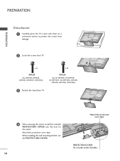
x 4 M4x28 (For 60PV250, 60PV400, 60PV450, 60PV450C, 60PV550U) x 4 M4x26 (For 42/50PT200, 42/50PT350, 42/50PT350C, 42/50PT250U, 50PV400, 50PV450, 50PV450C, 50PV550U) 3 Detach the stand from TV. When installing the wall mounting bracket, use the PROTECTION COVER. 14 Attach the protection cover tape. PROTECTION COVER Fix a Guide to protect the screen from damage. 2 Loose...
x 4 M4x28 (For 60PV250, 60PV400, 60PV450, 60PV450C, 60PV550U) x 4 M4x26 (For 42/50PT200, 42/50PT350, 42/50PT350C, 42/50PT250U, 50PV400, 50PV450, 50PV450C, 50PV550U) 3 Detach the stand from TV. When installing the wall mounting bracket, use the PROTECTION COVER. 14 Attach the protection cover tape. PROTECTION COVER Fix a Guide to protect the screen from damage. 2 Loose...
Owner's Manual
Page 17
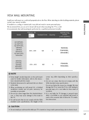
...injury. G LG is turned on a solid wall perpendicular to a fall and result in the table. Model VESA (A * B) A Standard Screw Quantity B Wall Mounting bracket (sold separately) 42/50PT200, 42/50PT350, 42/50PT350C, 50PV400, 50PV450, 50PV450C, 400 * 400 M6 42/50PT250U, 50PV550U PSW400B, 4 PSW400BG, DSW400BG 60PV250, 60PV400, ...while your TV is not liable for these kinds of the screws may fall , leading to electric shock. 17 G Do not use an LG brand wall mount when mounting the TV to the TV. If installed on a ceiling or slanted wall, it may differ depending...
...injury. G LG is turned on a solid wall perpendicular to a fall and result in the table. Model VESA (A * B) A Standard Screw Quantity B Wall Mounting bracket (sold separately) 42/50PT200, 42/50PT350, 42/50PT350C, 50PV400, 50PV450, 50PV450C, 400 * 400 M6 42/50PT250U, 50PV550U PSW400B, 4 PSW400BG, DSW400BG 60PV250, 60PV400, ...while your TV is not liable for these kinds of the screws may fall , leading to electric shock. 17 G Do not use an LG brand wall mount when mounting the TV to the TV. If installed on a ceiling or slanted wall, it may differ depending...
Owner's Manual
Page 18
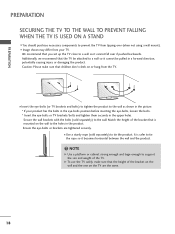
...I You should purchase necessary components to prevent the TV from the TV. Secure the wall brackets with the bolts (sold separately) to the wall. I Use a sturdy rope (sold separately) to tie the product. Ensure the eye-bolts or brackets are the same. 18 I Insert the eye-bolts (or TV... pushed backwards. We recommend that children don't climb on the wall to tie the rope so it cannot be pulled in the product. NOTE G Use a platform or cabinet strong enough and large enough to a wall so it becomes horizontal between the wall and the product. ! Caution: Please make...
...I You should purchase necessary components to prevent the TV from the TV. Secure the wall brackets with the bolts (sold separately) to the wall. I Use a sturdy rope (sold separately) to tie the product. Ensure the eye-bolts or brackets are the same. 18 I Insert the eye-bolts (or TV... pushed backwards. We recommend that children don't climb on the wall to tie the rope so it cannot be pulled in the product. NOTE G Use a platform or cabinet strong enough and large enough to a wall so it becomes horizontal between the wall and the product. ! Caution: Please make...
Owner's Manual
Page 20
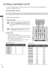
... the Component1 input source on the TV using the INPUT button on the TV. operation) I Turn on the digital set-top box. (Refer to the owner's manual for the digital set -top box ...
... the Component1 input source on the TV using the INPUT button on the TV. operation) I Turn on the digital set-top box. (Refer to the owner's manual for the digital set -top box ...
Owner's Manual
Page 21
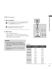
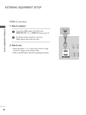
... the HDMI1, 2, or 3 input source on the TV using the INPUT button on the TV. 2 No separate audio connection is necessary. EXTERNAL EQUIPMENT SETUP HDMI Connection 1. HDMI supports both audio and video. 2. NOTE G If ... 60.00 59.94 60.00 59.94 60.00 24.00 30.00 59.939 60.00 23.94 29.97 21 How to use the latest cables that support High Speed HDMI. G HDMI mode supports PCM, AC-3(Dolby Digital) audio format.
... the HDMI1, 2, or 3 input source on the TV using the INPUT button on the TV. 2 No separate audio connection is necessary. EXTERNAL EQUIPMENT SETUP HDMI Connection 1. HDMI supports both audio and video. 2. NOTE G If ... 60.00 59.94 60.00 59.94 60.00 24.00 30.00 59.939 60.00 23.94 29.97 21 How to use the latest cables that support High Speed HDMI. G HDMI mode supports PCM, AC-3(Dolby Digital) audio format.
Owner's Manual
Page 22
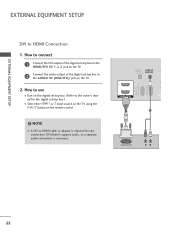
... the HDMI1 or 2 input source on the TV using the INPUT button on the TV. 2. NOTE G A DVI to HDMI Connection 1. DVI doesn't support audio, so a separate audio connection is required for the digital set-...
... the HDMI1 or 2 input source on the TV using the INPUT button on the TV. 2. NOTE G A DVI to HDMI Connection 1. DVI doesn't support audio, so a separate audio connection is required for the digital set-...
Owner's Manual
Page 23
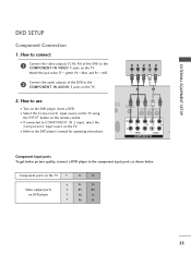
...the DVD player's manual for operating instructions. Y PB PR L R 1 2 2. Component ports on the TV Y Y Video output ports Y on the remote control. I Refer to use I Turn on the TV. Match the jack colors (Y = green, PB = blue, and PR = red). 2 Connect the audio outputs of the DVD to the component input... ports as shown below. I Select the Component1 input source on the TV using the INPUT button on DVD player Y Y PB PR PB PR B-Y R-Y Cb Cr Pb Pr 23 DIO IN B/DVI) REMOTE CONTROL IN AV IN ...
...the DVD player's manual for operating instructions. Y PB PR L R 1 2 2. Component ports on the TV Y Y Video output ports Y on the remote control. I Refer to use I Turn on the TV. Match the jack colors (Y = green, PB = blue, and PR = red). 2 Connect the audio outputs of the DVD to the component input... ports as shown below. I Select the Component1 input source on the TV using the INPUT button on DVD player Y Y PB PR PB PR B-Y R-Y Cb Cr Pb Pr 23 DIO IN B/DVI) REMOTE CONTROL IN AV IN ...
Owner's Manual
Page 24
How to use I Refer to the HDMI/DVI IN 1, 2, or HDMI IN 3 jack on the remote control. How to connect 1 Connect the HDMI output of the DVD to the DVD player's manual for operating instructions. HDMI-DTV OUTPUT 1 OPTICAL DIGITAL AUDIO AUDIO OUT (RGB/DV 2 1 HDMI/DVI IN RS-232C IN (CONTROL & SERVICE) RGB IN(PC) 24 I Select the HDMI1, 2, or 3 input source on the TV using the INPUT button on the TV. 2 No separate audio connection is necessary. HDMI supports both audio and video. 2. EXTERNAL EQUIPMENT SETUP EXTERNAL EQUIPMENT SETUP HDMI Connection 1.
How to use I Refer to the HDMI/DVI IN 1, 2, or HDMI IN 3 jack on the remote control. How to connect 1 Connect the HDMI output of the DVD to the DVD player's manual for operating instructions. HDMI-DTV OUTPUT 1 OPTICAL DIGITAL AUDIO AUDIO OUT (RGB/DV 2 1 HDMI/DVI IN RS-232C IN (CONTROL & SERVICE) RGB IN(PC) 24 I Select the HDMI1, 2, or 3 input source on the TV using the INPUT button on the TV. 2 No separate audio connection is necessary. HDMI supports both audio and video. 2. EXTERNAL EQUIPMENT SETUP EXTERNAL EQUIPMENT SETUP HDMI Connection 1.
Owner's Manual
Page 25
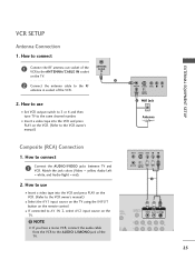
...'s manual.) I Insert a video tape into the VCR and press PLAY on the VCR. (Refer to the same channel number. How to use I Select the A V 1 input source on the TV using the INPUT button on the remote control. How to the VCR owner's manual.) ANT OUT S-VIDEO VIDEO L R ANT IN OUTPUT SWITCH 2 Wall...
...'s manual.) I Insert a video tape into the VCR and press PLAY on the VCR. (Refer to the same channel number. How to use I Select the A V 1 input source on the TV using the INPUT button on the remote control. How to the VCR owner's manual.) ANT OUT S-VIDEO VIDEO L R ANT IN OUTPUT SWITCH 2 Wall...
Owner's Manual
Page 26
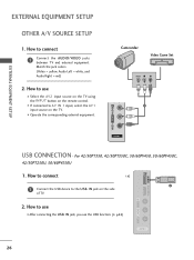
... IN 3 AV IN 2 VIDEO L/MONO AUDIO R HDMI IN 3 USB IN USB CONNECTION - I N jack on the side of TV. 2. How to use I After connecting the USB I N jack, you use I If connected to use the USB function. (G p.52) AV IN 2 26 Match the jack colors. (Video = yellow, Audio Left = white, and Audio Right = red) 2....connect 1 Connect the AUDIO/VIDEO jacks between TV and external equipment. EXTERNAL EQUIPMENT SETUP OTHER A/V SOURCE SETUP 1. I Select the A V 2 input source on the TV using the INPUT button on the TV. How to the USB I Operate the corresponding external equipment.
... IN 3 AV IN 2 VIDEO L/MONO AUDIO R HDMI IN 3 USB IN USB CONNECTION - I N jack on the side of TV. 2. How to use I After connecting the USB I N jack, you use I If connected to use the USB function. (G p.52) AV IN 2 26 Match the jack colors. (Video = yellow, Audio Left = white, and Audio Right = red) 2....connect 1 Connect the AUDIO/VIDEO jacks between TV and external equipment. EXTERNAL EQUIPMENT SETUP OTHER A/V SOURCE SETUP 1. I Select the A V 2 input source on the TV using the INPUT button on the TV. How to the USB I Operate the corresponding external equipment.
Owner's Manual
Page 28
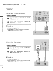
I Select the HDMI1 or 2 input source on the TV using the INPUT button on the remote control. 28 OPTICAL AUDIO IN DIGITAL (RGB/DVI) C AUDIO OUT RS-232C IN (CONTROL & ... (RGB/DVI) jack on the TV. 2. I Select the RGB-PC input source on the TV using the INPUT button on the remote control. How to use I Turn on the PC and the TV. How to the AUDIO IN (RGB/DVI) jack on the... VGA output of the PC to the HDMI/DVI IN 1 or 2 jack on the TV. 2 Connect the PC audio output to use I Turn on the PC and the TV. How to connect 1 Connect the DVI output of the PC to the RGB IN (P...
I Select the HDMI1 or 2 input source on the TV using the INPUT button on the remote control. 28 OPTICAL AUDIO IN DIGITAL (RGB/DVI) C AUDIO OUT RS-232C IN (CONTROL & ... (RGB/DVI) jack on the TV. 2. I Select the RGB-PC input source on the TV using the INPUT button on the remote control. How to use I Turn on the PC and the TV. How to the AUDIO IN (RGB/DVI) jack on the... VGA output of the PC to the HDMI/DVI IN 1 or 2 jack on the TV. 2 Connect the PC audio output to use I Turn on the PC and the TV. How to connect 1 Connect the DVI output of the PC to the RGB IN (P...
Owner's Manual
Page 29
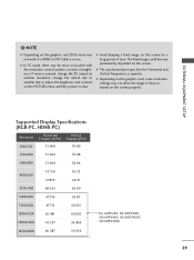
... on the screen for Horizontal and Vertical frequencies is clear. G In PC mode, there may not allow the image to DVI Cable is in use. G Avoid keeping a fixed image on the screen properly. Supported Display Specifications (RGB-PC, HDMI-PC) Resolution Horizontal Vertical Frequency(KHz) Frequency(Hz... 47.776 59.87 1360x768 47.712 60.015 1280x1024 63.981 60.020 1600x1200 74.537 59.869 1920x1080 66.587 59.934 For 60PV250, 50/60PV400, 50/60PV450, 50/60PV450C, 50/60PV550U 29 EXTERNAL EQUIPMENT SETUP ! G The synchronization input form for a long period of time. ...
... on the screen for Horizontal and Vertical frequencies is clear. G In PC mode, there may not allow the image to DVI Cable is in use. G Avoid keeping a fixed image on the screen properly. Supported Display Specifications (RGB-PC, HDMI-PC) Resolution Horizontal Vertical Frequency(KHz) Frequency(Hz... 47.776 59.87 1360x768 47.712 60.015 1280x1024 63.981 60.020 1600x1200 74.537 59.869 1920x1080 66.587 59.934 For 60PV250, 50/60PV400, 50/60PV450, 50/60PV450C, 50/60PV550U 29 EXTERNAL EQUIPMENT SETUP ! G The synchronization input form for a long period of time. ...


