
Owner's Manual
Page 1
OWNER'S MANUAL PLASMA TV Please read this manual carefully before operating your set and retain it for future reference. 42PT200 50PT200 42PT330 50PT330 42PT350 50PT350 50PV400 60PV400 50PV430 60PV430 50PV450 60PV450 42PT250U 50PT250U 50PV550U 60PV550U 42PT350C 50PT350C 50PV450C 60PV450C P/NO : SAC34173308(1102-REV02) www.lg.com
OWNER'S MANUAL PLASMA TV Please read this manual carefully before operating your set and retain it for future reference. 42PT200 50PT200 42PT330 50PT330 42PT350 50PT350 50PV400 60PV400 50PV430 60PV430 50PV450 60PV450 42PT250U 50PT250U 50PV550U 60PV550U 42PT350C 50PT350C 50PV450C 60PV450C P/NO : SAC34173308(1102-REV02) www.lg.com

Owner's Manual
Page 4
... attention to unplug the TV. 15 WARNING - Do not make sure 12 not to be connected to prevent possible electric shock (i.e. Do not install this owner's manual to install the TV by the hanging power and signal cables on the wall, make the TV with an exact replacement part by connecting it...
... attention to unplug the TV. 15 WARNING - Do not make sure 12 not to be connected to prevent possible electric shock (i.e. Do not install this owner's manual to install the TV by the hanging power and signal cables on the wall, make the TV with an exact replacement part by connecting it...
Owner's Manual
Page 9
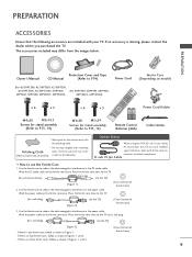
The accessories included may cause (Not included with your TV. PREPARATION Owner's Manual Protection Cover and Tape CD Manual (Refer to P.14) Power Cord (For 42/50PT200, 42/50PT330, 42/50PT350, 42/50PT350C, 42/50PT250U, 50PV400, (For 60PV400, 60PV430, 60PV450, 50PV430, 50PV450, 50PV450C, 50PV550U) 60PV450C, 60PV550U) Ferrite Core (Depending on model) x 4 x 3 M4x26 M5x14.5 Screws for...
The accessories included may cause (Not included with your TV. PREPARATION Owner's Manual Protection Cover and Tape CD Manual (Refer to P.14) Power Cord (For 42/50PT200, 42/50PT330, 42/50PT350, 42/50PT350C, 42/50PT250U, 50PV400, (For 60PV400, 60PV430, 60PV450, 50PV430, 50PV450, 50PV450C, 50PV550U) 60PV450C, 60PV550U) Ferrite Core (Depending on model) x 4 x 3 M4x26 M5x14.5 Screws for...
Owner's Manual
Page 20
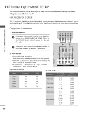
... 1 Connect the video outputs (Y, PB, PR) of the digital set -top box. How to use s Turn on the digital set-top box. (Refer to the owner's manual for the digital set -top box or other digital external device, refer to the COMPONENT IN AUDIO 1 jacks on the TV. operation) s Select the Component1...
... 1 Connect the video outputs (Y, PB, PR) of the digital set -top box. How to use s Turn on the digital set-top box. (Refer to the owner's manual for the digital set -top box or other digital external device, refer to the COMPONENT IN AUDIO 1 jacks on the TV. operation) s Select the Component1...
Owner's Manual
Page 21
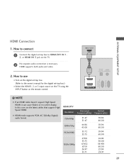
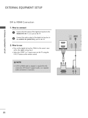
EXTERNAL EQUIPMENT SETUP HDMI Connection 1. In this case use I Turn on the digital set-top box. (Refer to the owner's manual for the digital set -top box to HDMI/DVI IN 1, 2, or HDMI IN 3 jack on the remote control. HDMI-DTV OUTPUT 1 OPTICAL DIGITAL AUDIO AUDIO ...
EXTERNAL EQUIPMENT SETUP HDMI Connection 1. In this case use I Turn on the digital set-top box. (Refer to the owner's manual for the digital set -top box to HDMI/DVI IN 1, 2, or HDMI IN 3 jack on the remote control. HDMI-DTV OUTPUT 1 OPTICAL DIGITAL AUDIO AUDIO ...
Owner's Manual
Page 22
... on the TV. 2 Connect the audio output of the digital set -top box. (Refer to HDMI cable or adapter is necessary. NOTE G A DVI to the owner's manual for this connection. OPTICAL DIGITAL AUDIO IN RE CON AUDIO OUT (RGB/DVI) RS-232C IN (CONTROL & SERVICE) RGB IN (PC) 2 2 1 1 HDMI/DVI IN 1 2 DVI...
... on the TV. 2 Connect the audio output of the digital set -top box. (Refer to HDMI cable or adapter is necessary. NOTE G A DVI to the owner's manual for this connection. OPTICAL DIGITAL AUDIO IN RE CON AUDIO OUT (RGB/DVI) RS-232C IN (CONTROL & SERVICE) RGB IN (PC) 2 2 1 1 HDMI/DVI IN 1 2 DVI...
Owner's Manual
Page 25
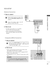
NOTE G If you have a mono VCR, connect the audio cable from the VCR to the VCR owner's manual.) ANT OUT S-VIDEO VIDEO L R ANT IN OUTPUT SWITCH 2 Wall Jack Antenna Composite (RCA) Connection 1. I Set VCR output switch to 3 or 4 and then tune TV to ... to connect 1 Connect the RF antenna out socket of the VCR. 2. I If connected to the RF antenna in socket of the VCR to the VCR owner's manual.) I Insert a video tape into the VCR and press PLAY on the TV. Match the jack colors (Video = yellow, Audio Left = white, and Audio Right = red...
NOTE G If you have a mono VCR, connect the audio cable from the VCR to the VCR owner's manual.) ANT OUT S-VIDEO VIDEO L R ANT IN OUTPUT SWITCH 2 Wall Jack Antenna Composite (RCA) Connection 1. I Set VCR output switch to 3 or 4 and then tune TV to ... to connect 1 Connect the RF antenna out socket of the VCR. 2. I If connected to the RF antenna in socket of the VCR to the VCR owner's manual.) I Insert a video tape into the VCR and press PLAY on the TV. Match the jack colors (Video = yellow, Audio Left = white, and Audio Right = red...


