Owner's Manual (English)
Page 3
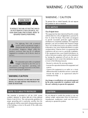
... important operating and maintenance (servicing) instructions in a residential installation. FCC NOTICE Class B digital device This equipment has been tested and found to comply with the instructions, may be connected to the grounding system of the National Electric Code (U.S.A.). Reorient or relocate the receiving antenna. - Any changes or modifications not expressly approved by turning the equipment off and on a circuit different from LG Electronics...
... important operating and maintenance (servicing) instructions in a residential installation. FCC NOTICE Class B digital device This equipment has been tested and found to comply with the instructions, may be connected to the grounding system of the National Electric Code (U.S.A.). Reorient or relocate the receiving antenna. - Any changes or modifications not expressly approved by turning the equipment off and on a circuit different from LG Electronics...
Owner's Manual (English)
Page 6
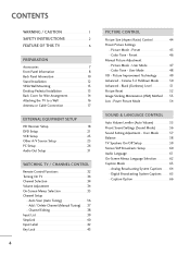
... 8 Back Panel Information 10 Stand Installation 12 VESA Wall Mounting 13 Desktop Pedestal Installation 13 Back Cover for Wire Arrangement 14 Attaching the TV to a Wall 16 Antenna or Cable Connection 17 EXTERNAL EQUIPMENT SETUP HD Receiver Setup 18 DVD Setup 21 VCR Setup 23 Other A/V Source Setup 25 PC Setup 26 Audio Out Setup 31 WATCHING TV / CHANNEL CONTROL Remote Control Functions 32 Turning On TV 34 Channel Selection 34 Volume Adjustment 34 On-Screen Menus Selection 35 Channel Setup - Auto Scan (Auto Tuning 36 - Preset 46 Manual Picture Adjustment - Digital...
... 8 Back Panel Information 10 Stand Installation 12 VESA Wall Mounting 13 Desktop Pedestal Installation 13 Back Cover for Wire Arrangement 14 Attaching the TV to a Wall 16 Antenna or Cable Connection 17 EXTERNAL EQUIPMENT SETUP HD Receiver Setup 18 DVD Setup 21 VCR Setup 23 Other A/V Source Setup 25 PC Setup 26 Audio Out Setup 31 WATCHING TV / CHANNEL CONTROL Remote Control Functions 32 Turning On TV 34 Channel Selection 34 Volume Adjustment 34 On-Screen Menus Selection 35 Channel Setup - Auto Scan (Auto Tuning 36 - Preset 46 Manual Picture Adjustment - Digital...
Owner's Manual (English)
Page 8
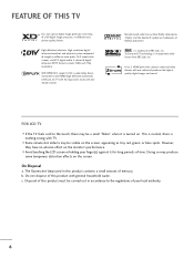
... must be carried out in this logo works easily with one remote control. High-definition television. b. Disposal of your finger(s) against it is nothing wrong with general household waste. With HDMI CEC support of LG's audio/video device connected to the touch, there may produce some temporary distortion effects on . FOR LCD TV I Avoid touching the LCD screen or holding your local authority. 6 On...
... must be carried out in this logo works easily with one remote control. High-definition television. b. Disposal of your finger(s) against it is nothing wrong with general household waste. With HDMI CEC support of LG's audio/video device connected to the touch, there may produce some temporary distortion effects on . FOR LCD TV I Avoid touching the LCD screen or holding your local authority. 6 On...
Owner's Manual (English)
Page 11
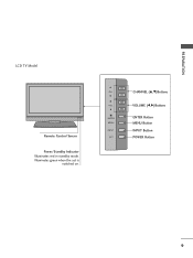
CH VOL ENTER MENU INPUT CH VOL ENTER MENU INPUT CHANNEL (D,E)Buttons VOLUME (F,G)Buttons ENTER Button MENU Button INPUT Button POWER Button 9 Illuminates green when the set is switched on. PREPARATION LCD TV Model Remote Control Sensor Power/Standby Indicator Illuminates red in standby mode.
CH VOL ENTER MENU INPUT CH VOL ENTER MENU INPUT CHANNEL (D,E)Buttons VOLUME (F,G)Buttons ENTER Button MENU Button INPUT Button POWER Button 9 Illuminates green when the set is switched on. PREPARATION LCD TV Model Remote Control Sensor Power/Standby Indicator Illuminates red in standby mode.
Owner's Manual (English)
Page 13
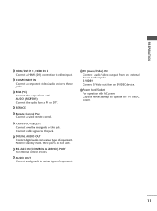
... remote control. 6 ANTENNA/CABLE IN Connect over-the air signals to this jack. Note: In standby mode, these jacks. PREPARATION 1 HDMI/DVI IN 1, HDMI IN 2 Connect a HDMI (DVI) connection to either input. 2 COMPONENT IN Connect a component video/audio device to these jacks. 3 RGB (PC) Connect the output from an external device to these ports do not work. 8 RS-232C IN (CONTROL & SERVICE) PORT For external control devices. 9 AUDIO OUT Connect analog audio to various types of equipment. S-VIDEO Connect S-Video out from an S-VIDEO device. 11 Power Cord Socket For operation...
... remote control. 6 ANTENNA/CABLE IN Connect over-the air signals to this jack. Note: In standby mode, these jacks. PREPARATION 1 HDMI/DVI IN 1, HDMI IN 2 Connect a HDMI (DVI) connection to either input. 2 COMPONENT IN Connect a component video/audio device to these jacks. 3 RGB (PC) Connect the output from an external device to these ports do not work. 8 RS-232C IN (CONTROL & SERVICE) PORT For external control devices. 9 AUDIO OUT Connect analog audio to various types of equipment. S-VIDEO Connect S-Video out from an S-VIDEO device. 11 Power Cord Socket For operation...
Owner's Manual (English)
Page 15
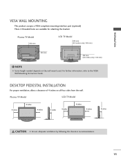
... to the VESA Wall Mounting Instruction Guide. ( ) DESKTOP PEDESTAL INSTALLATION ( ) For proper ventilation, allow a clearance of 4 inches on the wall mount used. Plasma TV Model 600 mm LCD TV Model 600 mm (32 inches only: 200 mm) R R 400 mm 400 mm (32 inches only: 100 mm) ! PREPARATION VESA WALL MOUNTING This product accepts a VESA-compliant mounting interface pad. (optional) There 4 threaded holes are available for attaching the bracket. NOTE G Screw length needed depends on all...
... to the VESA Wall Mounting Instruction Guide. ( ) DESKTOP PEDESTAL INSTALLATION ( ) For proper ventilation, allow a clearance of 4 inches on the wall mount used. Plasma TV Model 600 mm LCD TV Model 600 mm (32 inches only: 200 mm) R R 400 mm 400 mm (32 inches only: 100 mm) ! PREPARATION VESA WALL MOUNTING This product accepts a VESA-compliant mounting interface pad. (optional) There 4 threaded holes are available for attaching the bracket. NOTE G Screw length needed depends on all...
Owner's Manual (English)
Page 20
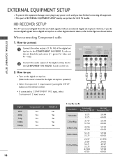
...(PC) AUDIO REM (RGB/DVI) SERVICE CONT COMPONENT IN 2 RS (CONTR 2 Connect the audio output of the digital set-top box to 1 the COMPONENT IN AUDIO 1 jacks on MI IN the set -top box or other digital external device, refer to the figure as shown below. How to the owner's manual for LCD TV model. Match the jack colors (Y = green, PB = blue, and PR = red). operation) I Select Component 1 input source by using the INPUT button on the digital set . Y PB PR L R Signal 480i...
...(PC) AUDIO REM (RGB/DVI) SERVICE CONT COMPONENT IN 2 RS (CONTR 2 Connect the audio output of the digital set-top box to 1 the COMPONENT IN AUDIO 1 jacks on MI IN the set -top box or other digital external device, refer to the figure as shown below. How to the owner's manual for LCD TV model. Match the jack colors (Y = green, PB = blue, and PR = red). operation) I Select Component 1 input source by using the INPUT button on the digital set . Y PB PR L R Signal 480i...
Owner's Manual (English)
Page 21
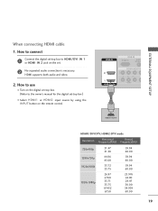
...use I Turn on the digital set-top box. (Refer to the owner's manual for the digital set-top box.) I Select HDMI1 or HDMI2 input source by using the INPUT button on the set -top box to connect 1 Connect the digital set . 2 No separated audio connection is necessary. EXTERNAL EQUIPMENT SETUP When connecting HDMI cable 1. HDMI IN RGB IN RGB(PC) AUDIO (RGB/D 2 2 1 1 HDMI/DVI IN COMPONENT IN VIDEO 1 HDMI-DTV OUTPUT HDMI1/DVI-DTV, HDMI2-DTV mode Resolution....00 19 HDMI supports both audio and video. ( ) 2. How to HDMI/DVI IN 1 or HDMI IN 2 jack on the remote control.
...use I Turn on the digital set-top box. (Refer to the owner's manual for the digital set-top box.) I Select HDMI1 or HDMI2 input source by using the INPUT button on the set -top box to connect 1 Connect the digital set . 2 No separated audio connection is necessary. EXTERNAL EQUIPMENT SETUP When connecting HDMI cable 1. HDMI IN RGB IN RGB(PC) AUDIO (RGB/D 2 2 1 1 HDMI/DVI IN COMPONENT IN VIDEO 1 HDMI-DTV OUTPUT HDMI1/DVI-DTV, HDMI2-DTV mode Resolution....00 19 HDMI supports both audio and video. ( ) 2. How to HDMI/DVI IN 1 or HDMI IN 2 jack on the remote control.
Owner's Manual (English)
Page 22
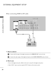
... use I Turn on the digital set-top box. (Refer to the owner's manual for the digital set-top box.) I Select HDMI1 input source by using the INPUT button on the set -top box to DVI cable HDMI IN ANTENNA/ CABLE IN RGB IN DIGITAL RGB(PC) AUDIO REMOTE AUDIO OUT (RGB/DVI) SERVICE CONTROL IN OPTICAL 2 2 1 1 HDMI/DVI IN COMPONENT IN RS-232C IN (CONTROL & SERVICE) AUDIO OUT VIDEO AUDIO S-VIDEO VIDEO (MONO) AUDIO 2 1 AV IN 1 DVI-DTV OUTPUT L R 1. EXTERNAL EQUIPMENT SETUP EXTERNAL EQUIPMENT SETUP When connecting HDMI to the AUDIO (RGB/DVI) jack on the remote control...
... use I Turn on the digital set-top box. (Refer to the owner's manual for the digital set-top box.) I Select HDMI1 input source by using the INPUT button on the set -top box to DVI cable HDMI IN ANTENNA/ CABLE IN RGB IN DIGITAL RGB(PC) AUDIO REMOTE AUDIO OUT (RGB/DVI) SERVICE CONTROL IN OPTICAL 2 2 1 1 HDMI/DVI IN COMPONENT IN RS-232C IN (CONTROL & SERVICE) AUDIO OUT VIDEO AUDIO S-VIDEO VIDEO (MONO) AUDIO 2 1 AV IN 1 DVI-DTV OUTPUT L R 1. EXTERNAL EQUIPMENT SETUP EXTERNAL EQUIPMENT SETUP When connecting HDMI to the AUDIO (RGB/DVI) jack on the remote control...
Owner's Manual (English)
Page 23
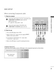
... DVD player, insert a DVD. I Turn on the set . Component ports on the TV Y PB PR Video output ports on the remote control. How to connect EXTERNAL EQUIPMENT SETUP 1 Connect the video outputs (Y, PB, PR) of the DVD to the COMPONENT IN VIDEO1 jacks on the set . How to the DVD player's manual for operating instructions. DVD SETUP When connecting Component cable 1. I If connected to COMPONENT IN 2 input, select Component 2 input source. 1 2 I Refer to use 1 VI IN VIDEO AUDIO S-VI ( ) I Select Component 1 input source by using the INPUT button on DVD player...
... DVD player, insert a DVD. I Turn on the set . Component ports on the TV Y PB PR Video output ports on the remote control. How to connect EXTERNAL EQUIPMENT SETUP 1 Connect the video outputs (Y, PB, PR) of the DVD to the COMPONENT IN VIDEO1 jacks on the set . How to the DVD player's manual for operating instructions. DVD SETUP When connecting Component cable 1. I If connected to COMPONENT IN 2 input, select Component 2 input source. 1 2 I Refer to use 1 VI IN VIDEO AUDIO S-VI ( ) I Select Component 1 input source by using the INPUT button on DVD player...
Owner's Manual (English)
Page 24
... the DVD player's manual for operating instructions. I Select HDMI1 or HDMI2 input source by using the INPUT button on the remote control. I Refer to use I Select A V 1 input source by using the INPUT button on the DVD player, insert a DVD. S-VIDEO AUDIO L R ANTENNA/ CABLE IN 1 2 DIGITAL IO REMOTE AUDIO OUT DVI) SERVICE CONTROL IN OPTICAL N RS-232C IN (CONTROL & SERVICE) AUDIO OUT AUDIO S-VIDEO VIDEO (MONO) AUDIO AV IN 1 When connecting HDMI cable 1. How to connect 1 Connect the HDMI output of the DVD to AV IN2, select A V 2 input source. I If connected...
... the DVD player's manual for operating instructions. I Select HDMI1 or HDMI2 input source by using the INPUT button on the remote control. I Refer to use I Select A V 1 input source by using the INPUT button on the DVD player, insert a DVD. S-VIDEO AUDIO L R ANTENNA/ CABLE IN 1 2 DIGITAL IO REMOTE AUDIO OUT DVI) SERVICE CONTROL IN OPTICAL N RS-232C IN (CONTROL & SERVICE) AUDIO OUT AUDIO S-VIDEO VIDEO (MONO) AUDIO AV IN 1 When connecting HDMI cable 1. How to connect 1 Connect the HDMI output of the DVD to AV IN2, select A V 2 input source. I If connected...

Owner's Manual (English)
Page 26
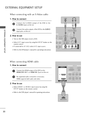
... PLAY on the VCR. (Refer to the VCR owner's manual.) I If connected to both Video and the S-Video cables, only the S-Video will work. 24 How to connect 1 Connect the S-VIDEO output of the VCR to AV IN2, select A V 2 input source. ! ( ) EXTERNAL EQUIPMENT SETUP EXTERNAL EQUIPMENT SETUP When connecting with an S-Video cable 1. I Select A V 1 input source by using the INPUT button on the remote control. UDIO B/DVI) ANTENNA/ CABLE IN 1 2 DIGITAL REMOTE AUDIO O( UT) SERVICE CONTROL IN OPTICAL T IN RS-232C IN (CONTROL & SERVICE) AUDIO OUT AV IN 1 AUDIO S-VIDEO VIDEO...
... PLAY on the VCR. (Refer to the VCR owner's manual.) I If connected to both Video and the S-Video cables, only the S-Video will work. 24 How to connect 1 Connect the S-VIDEO output of the VCR to AV IN2, select A V 2 input source. ! ( ) EXTERNAL EQUIPMENT SETUP EXTERNAL EQUIPMENT SETUP When connecting with an S-Video cable 1. I Select A V 1 input source by using the INPUT button on the remote control. UDIO B/DVI) ANTENNA/ CABLE IN 1 2 DIGITAL REMOTE AUDIO O( UT) SERVICE CONTROL IN OPTICAL T IN RS-232C IN (CONTROL & SERVICE) AUDIO OUT AV IN 1 AUDIO S-VIDEO VIDEO...
Owner's Manual (English)
Page 28
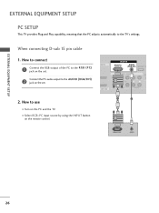
... 2 1 I/DVI IN VIDEO AUDIO 1 2 RGB OUTPUT AUDIO 26 When connecting D-sub 15 pin cable 1. Connect the PC audio output to the R GB (P C) jack on the set . 2. How to connect 1 Connect the RGB output of the PC to the AUDIO (RGB/DVI) 2 jack on the set . EXTERNAL EQUIPMENT SETUP EXTERNAL EQUIPMENT SETUP PC SETUP This TV provides Plug and Play capability, meaning that the PC adjusts automatically to use I Select RGB-PC input source by using the INPUT button on the remote control.
... 2 1 I/DVI IN VIDEO AUDIO 1 2 RGB OUTPUT AUDIO 26 When connecting D-sub 15 pin cable 1. Connect the PC audio output to the R GB (P C) jack on the set . 2. How to connect 1 Connect the RGB output of the PC to the AUDIO (RGB/DVI) 2 jack on the set . EXTERNAL EQUIPMENT SETUP EXTERNAL EQUIPMENT SETUP PC SETUP This TV provides Plug and Play capability, meaning that the PC adjusts automatically to use I Select RGB-PC input source by using the INPUT button on the remote control.
Owner's Manual (English)
Page 31
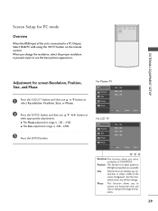
... Size adjustment range is connected to a PC Output, Select RGB-PC with using the INPUT button on the screen background. For Plasma TV Resolution Position Size 1024 x 768 1280 x 768 1360 x 768 Phase Reset D MENU Prev E Select Ok For LCD TV Resolution Position Size Phase 1024 x 768 1280 x 768 1360 x 768 1366 x 768 Reset D MENU Prev E Select Ok 123 Resolution This function allows you change . PICTURE SOUND SAP CC ADJUST EXTERNAL EQUIPMENT SETUP Adjustment for PC mode Overview...
... Size adjustment range is connected to a PC Output, Select RGB-PC with using the INPUT button on the screen background. For Plasma TV Resolution Position Size 1024 x 768 1280 x 768 1360 x 768 Phase Reset D MENU Prev E Select Ok For LCD TV Resolution Position Size Phase 1024 x 768 1280 x 768 1360 x 768 1366 x 768 Reset D MENU Prev E Select Ok 123 Resolution This function allows you change . PICTURE SOUND SAP CC ADJUST EXTERNAL EQUIPMENT SETUP Adjustment for PC mode Overview...
Owner's Manual (English)
Page 33
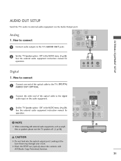
... CONTROL IN OPTICAL Analog 1. See the external audio equipment instruction manual for operation. Off" in the AUDIO menu. (G p.59). Off" in the AUDIO menu. (G p.59). G Block the SPDIF out (optical) about the contents with external audio equipments, such as amplifiers or speakers, please turn the TV speakers off. (G p.59) ANTENNA/ CABLE IN DIGITAL O REMOTE AUDIO OUT VI) SERVICE CONTROL IN OPTICAL N RS-232C IN 1 (CONTROL & SERVICE) AUDIO OUT AUDIO S-VIDEO VIDEO (MONO) AUDIO 2 AV IN 1 CAUTION G Do not look into the optical output port. Digital 1. How to connect...
... CONTROL IN OPTICAL Analog 1. See the external audio equipment instruction manual for operation. Off" in the AUDIO menu. (G p.59). Off" in the AUDIO menu. (G p.59). G Block the SPDIF out (optical) about the contents with external audio equipments, such as amplifiers or speakers, please turn the TV speakers off. (G p.59) ANTENNA/ CABLE IN DIGITAL O REMOTE AUDIO OUT VI) SERVICE CONTROL IN OPTICAL N RS-232C IN 1 (CONTROL & SERVICE) AUDIO OUT AUDIO S-VIDEO VIDEO (MONO) AUDIO 2 AV IN 1 CAUTION G Do not look into the optical output port. Digital 1. How to connect...
Owner's Manual (English)
Page 34
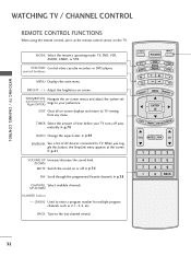
... remote control sensor on the TV. TV INPUT POWER TV AUDIO DVD MODE CABLE INPUT VCR STB BRIGHT - THUMBSTICK Navigate the on -screen displays and return to your TV turns off . G p.38 CHANNEL Select available channels. EXIT Clear all on -screen menus and adjust the system set- (Up/Down/Left Right/ENTER) tings to TV viewing from any menu. G p.41 VOLUME UP Increase/decrease the sound level. /DOWN MUTE Switch the sound on screen. UP/DOWN NUMBER button - (DASH) Used to the last channel viewed. MENU...
... remote control sensor on the TV. TV INPUT POWER TV AUDIO DVD MODE CABLE INPUT VCR STB BRIGHT - THUMBSTICK Navigate the on -screen displays and return to your TV turns off . G p.38 CHANNEL Select available channels. EXIT Clear all on -screen menus and adjust the system set- (Up/Down/Left Right/ENTER) tings to TV viewing from any menu. G p.41 VOLUME UP Increase/decrease the sound level. /DOWN MUTE Switch the sound on screen. UP/DOWN NUMBER button - (DASH) Used to the last channel viewed. MENU...
Owner's Manual (English)
Page 74
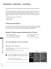
...) I TV-Y (All children) I TV-Y7 (Children 7 years older) SET PASSWORD & LOCK SYSTEM Setting up Your Password Set up with the initial password "0-0-0-0". PARENTAL CONTROL / RATINGS Parental Control can be used to -video movies use the Movie Rating System (MPAA) only. Set ratings and categories to block specific channels, ratings and other viewing sources. To use this menu. 1 Press the MENU button and then use the D or E button to be viewed. Viewing can be blocked by broadcasting stations. Most television programs and television...
...) I TV-Y (All children) I TV-Y7 (Children 7 years older) SET PASSWORD & LOCK SYSTEM Setting up Your Password Set up with the initial password "0-0-0-0". PARENTAL CONTROL / RATINGS Parental Control can be used to -video movies use the Movie Rating System (MPAA) only. Set ratings and categories to block specific channels, ratings and other viewing sources. To use this menu. 1 Press the MENU button and then use the D or E button to be viewed. Viewing can be blocked by broadcasting stations. Most television programs and television...
Owner's Manual (English)
Page 83
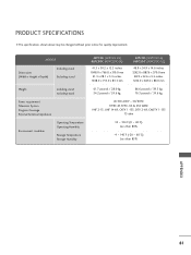
MODELS Dimensions (Width x Height x Depth) Including stand Excluding stand Weight including stand excluding stand Power requirement Television System Program Coverage External Antenna Impedance Environment condition Operating Temperature Operating Humidity Storage Temperature Storage Humidity 42PC5D (42PC5D-UL) 42PC5DC (42PC5DC-UL) 41.3 x 30.2 x 12.2 inches 1048.0 x 766.0 x 310.0 mm 41.3 x 28.1 x 3.3 inches 1048.0 x 713.0 x 83.5 mm 50PC5D (50PC5D-UL) 50PC5DC (50PC5DC-UL) 48.9 x 34.9 x 14.6 inches 1242.0 x 887.6 x 370.0 mm...
MODELS Dimensions (Width x Height x Depth) Including stand Excluding stand Weight including stand excluding stand Power requirement Television System Program Coverage External Antenna Impedance Environment condition Operating Temperature Operating Humidity Storage Temperature Storage Humidity 42PC5D (42PC5D-UL) 42PC5DC (42PC5DC-UL) 41.3 x 30.2 x 12.2 inches 1048.0 x 766.0 x 310.0 mm 41.3 x 28.1 x 3.3 inches 1048.0 x 713.0 x 83.5 mm 50PC5D (50PC5D-UL) 50PC5DC (50PC5DC-UL) 48.9 x 34.9 x 14.6 inches 1242.0 x 887.6 x 370.0 mm...
Owner's Manual (English)
Page 85
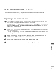
... button, the light blinks at the same time for 20 seconds, the light on the mode button will be programmed to repeat from step 2. 3 Enter the appropriate code from the code table on the following pages. APPENDIX 83 The program- In that , press the POWER button. If you have to operate most remote-controllable devices. If the device turned off . Programming a code into a remote mode 1 To find out whether your remote control can be turned...
... button, the light blinks at the same time for 20 seconds, the light on the mode button will be programmed to repeat from step 2. 3 Enter the appropriate code from the code table on the following pages. APPENDIX 83 The program- In that , press the POWER button. If you have to operate most remote-controllable devices. If the device turned off . Programming a code into a remote mode 1 To find out whether your remote control can be turned...
Owner's Manual (English)
Page 93
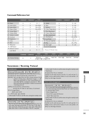
... of command. [Cr]: Carriage Return ASCII code '0x0D' [ ]: ASCII code 'space (0x20)' * In this format when receiving abnormal data from non-viable functions or communication errors. Red Adjustment k e 0~1 20. Error Acknowledgement [Command2][ ][Set ID][ ][NG][Data][x] The TV transmits ACK (acknowledgement) based on this model, TV will not send the status during the standby mode. Volume Mute k 07. Remote Control Lock Mode k a 0~1 15. Input Select x 04. Screen Mute k 06. Blue Adjustment k g 0 ~ 64 22.
... of command. [Cr]: Carriage Return ASCII code '0x0D' [ ]: ASCII code 'space (0x20)' * In this format when receiving abnormal data from non-viable functions or communication errors. Red Adjustment k e 0~1 20. Error Acknowledgement [Command2][ ][Set ID][ ][NG][Data][x] The TV transmits ACK (acknowledgement) based on this model, TV will not send the status during the standby mode. Volume Mute k 07. Remote Control Lock Mode k a 0~1 15. Input Select x 04. Screen Mute k 06. Blue Adjustment k g 0 ~ 64 22.


