Service Manual
Page 3
... AC power line. It will also protect the receiver and it is corresponds to the chassis the reading must not exceed 0.75 volt RMS which is returned to each exposed metallic part. Place the AC switch in the Schematic Diagram and Replacement Parts List. Reverse plug the AC cord into the AC outlet. Do not use a line Isolation Transformer during the servicing...
... AC power line. It will also protect the receiver and it is corresponds to the chassis the reading must not exceed 0.75 volt RMS which is returned to each exposed metallic part. Place the AC switch in the Schematic Diagram and Replacement Parts List. Reverse plug the AC cord into the AC outlet. Do not use a line Isolation Transformer during the servicing...
Service Manual
Page 4
... and well tinned. 4. c. Removing or reinstalling any component, circuit board module or any heat sink in this service manual. Connecting a test substitute in parallel with this receiver only the test fixtures specified in this receiver. Quickly move the soldering iron tip to 600 F) b. a. CAUTION: A wrong part substitution or incorrect polarity installation of 60 parts tin/40 parts lead. 3. The following...
... and well tinned. 4. c. Removing or reinstalling any component, circuit board module or any heat sink in this service manual. Connecting a test substitute in parallel with this receiver only the test fixtures specified in this receiver. Quickly move the soldering iron tip to 600 F) b. a. CAUTION: A wrong part substitution or incorrect polarity installation of 60 parts tin/40 parts lead. 3. The following...

Service Manual
Page 5
... board and crimp the "U" with the soldering iron tip as outlined in the circuit board. 5. Removal 1. Remove the heat sink mounting screw (if so equipped). 3. Diode Removal/Replacement 1. Insert new transistor in paragraphs 5 and 6 above. "Small-Signal" Discrete Transistor Removal/Replacement 1. Replacement 1. Remove at connections other side. At IC Connections To repair a defective copper pattern at IC connections use the standard technique as the solder melts. 2.
... board and crimp the "U" with the soldering iron tip as outlined in the circuit board. 5. Removal 1. Remove the heat sink mounting screw (if so equipped). 3. Diode Removal/Replacement 1. Insert new transistor in paragraphs 5 and 6 above. "Small-Signal" Discrete Transistor Removal/Replacement 1. Replacement 1. Remove at connections other side. At IC Connections To repair a defective copper pattern at IC connections use the standard technique as the solder melts. 2.

Service Manual
Page 6
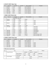
...~90 % LCD Module Remark (ZE/TE) EU/Non-EU (PAL Market) 6),7) South America Market 7) Except South America NTSC Market (ME) PAL FRANCE NTSC JAPAN 42.02inch(42LB1R) PAL, 200 PR.(Option) NTSC LPL -6- Picture Size 7. Input Voltage 5. RF Input Channel 4. Operating Environment 9. Storage Environment 10. Market 6. Tuning System 8. Video input applicable system 2. SPECIFICATION NOTE : Specifications and others are subject to change without notice...
...~90 % LCD Module Remark (ZE/TE) EU/Non-EU (PAL Market) 6),7) South America Market 7) Except South America NTSC Market (ME) PAL FRANCE NTSC JAPAN 42.02inch(42LB1R) PAL, 200 PR.(Option) NTSC LPL -6- Picture Size 7. Input Voltage 5. RF Input Channel 4. Operating Environment 9. Storage Environment 10. Market 6. Tuning System 8. Video input applicable system 2. SPECIFICATION NOTE : Specifications and others are subject to change without notice...

Service Manual
Page 7
...) 5 Power ON Stand by DPMS Mode Power off 6 LCD Module Specification Remark 42" TFT WXGA LCD H : 31 ~ 61Khz PC Input V : 56 ~ 75Hz 1) Contrast/Brightness 2) H-Position / V-Position 3) Tracking : Clock / Phase 4) Auto Configure 5) Reset 1 : Y Middle east / NTSC Area 3 : Pb 5 : Pr 7 : Line1 Ready 9 : LINE2 11: LINE3 13: Line3 Ready 2 : Y GND JAPAN Only 4 : Pb GND 6 : Pr GND 8 : LINE1 10:Line2 Ready 12:SWITCH GND 14: SWITCH H/V-Sync Video Power consumption LED...
...) 5 Power ON Stand by DPMS Mode Power off 6 LCD Module Specification Remark 42" TFT WXGA LCD H : 31 ~ 61Khz PC Input V : 56 ~ 75Hz 1) Contrast/Brightness 2) H-Position / V-Position 3) Tracking : Clock / Phase 4) Auto Configure 5) Reset 1 : Y Middle east / NTSC Area 3 : Pb 5 : Pr 7 : Line1 Ready 9 : LINE2 11: LINE3 13: Line3 Ready 2 : Y GND JAPAN Only 4 : Pb GND 6 : Pr GND 8 : LINE1 10:Line2 Ready 12:SWITCH GND 14: SWITCH H/V-Sync Video Power consumption LED...
Service Manual
Page 8
... white/All back LPL Typ. +0.03 4.Component Video Input (Y, PB, PR) No Resolution 1. 640x480 2. 640x480 3. 720x480 4. 720x576 5. 720x576 6. 1280x720 Specification H-freq(kHz) V-freq(Hz) 15.73...HDTV 1080i 60Hz (ATSC) TE, ME HDTV 1080i 59.94Hz TE, ME 5. 3.Optical Feature(LCD Module) No. Typ. Proposed VESA VESA VESA VESA VESA(XGA) VESA(XGA) VESA(XGA) VESA(WXGA) VESA(WXGA) Supported Item 1 Viewing Angle 2 Luminance 3 Contrast Ratio 4 CIE Color Coordinates R/L, U/D Luminance(cd/ ) Variation CR CRD (With Al) WHITE Wx Wy RED R Ry GREEN Gx Gy BLUE Bx By Specification...
... white/All back LPL Typ. +0.03 4.Component Video Input (Y, PB, PR) No Resolution 1. 640x480 2. 640x480 3. 720x480 4. 720x576 5. 720x576 6. 1280x720 Specification H-freq(kHz) V-freq(Hz) 15.73...HDTV 1080i 60Hz (ATSC) TE, ME HDTV 1080i 59.94Hz TE, ME 5. 3.Optical Feature(LCD Module) No. Typ. Proposed VESA VESA VESA VESA VESA(XGA) VESA(XGA) VESA(XGA) VESA(WXGA) VESA(WXGA) Supported Item 1 Viewing Angle 2 Luminance 3 Contrast Ratio 4 CIE Color Coordinates R/L, U/D Luminance(cd/ ) Variation CR CRD (With Al) WHITE Wx Wy RED R Ry GREEN Gx Gy BLUE Bx By Specification...
Service Manual
Page 9
...specification No, 1 Product Dimenson 2 Product Weight Item Before Packing After Packing Only SET With Box Width(W) 1175 1282 Content Length(D) 300 386 43.4Kg 48.2kg Height(H) 768 920 Remark With Stand With Stand -9- HDMI PC INPUT Mode Table No Resolution 1 720x400 2 640x480 3 800x600 4 832x624 5 1024x768 6 1280x768 7 1360x768 8 1366x768 9 1920x1080 10 1280x720 H-freq(kHz) V-freq.(Hz) Analog RGB, Digital....50 84.75 84.75 86.375 74.375 Proposed VESA VESA VESA VESA VESA(XGA) VESA(XGA) VESA(XGA) VESA(WXGA) VESA(WXGA) Supported HDCP DVI Digital 1080i HDCP DVI Digital 720p 8.
...specification No, 1 Product Dimenson 2 Product Weight Item Before Packing After Packing Only SET With Box Width(W) 1175 1282 Content Length(D) 300 386 43.4Kg 48.2kg Height(H) 768 920 Remark With Stand With Stand -9- HDMI PC INPUT Mode Table No Resolution 1 720x400 2 640x480 3 800x600 4 832x624 5 1024x768 6 1280x768 7 1360x768 8 1366x768 9 1920x1080 10 1280x720 H-freq(kHz) V-freq.(Hz) Analog RGB, Digital....50 84.75 84.75 86.375 74.375 Proposed VESA VESA VESA VESA VESA(XGA) VESA(XGA) VESA(XGA) VESA(WXGA) VESA(WXGA) Supported HDCP DVI Digital 1080i HDCP DVI Digital 720p 8.

Service Manual
Page 10
...TV Mode - 0.7 V 0.7 V High (1 - 3V) - Wide Screen Low (0 - 2V) - Wide Screen Low (0 - 2V) - Mechanical specification Scart Arrangement 1.(Full Scart) Pin Signal 1 Audio Output B (right) 2 Audio Input B (right) 3 Audio Output A (left) 4 Ground (audio) 5 Ground (blue) 6 Audio input A (left) 7 Blue input 8 Function Select (AV control) 9 Ground (Green) 10 Comms Data 2 11 Green input 12 Comms Data 1 13 Ground (Red) 14 Ground (Blanking) 15 Red input 16 RGB Switching Control 17 Ground (Video input & Output) 18 Ground (RGB Switching Control) 19 Video output...
...TV Mode - 0.7 V 0.7 V High (1 - 3V) - Wide Screen Low (0 - 2V) - Wide Screen Low (0 - 2V) - Mechanical specification Scart Arrangement 1.(Full Scart) Pin Signal 1 Audio Output B (right) 2 Audio Input B (right) 3 Audio Output A (left) 4 Ground (audio) 5 Ground (blue) 6 Audio input A (left) 7 Blue input 8 Function Select (AV control) 9 Ground (Green) 10 Comms Data 2 11 Green input 12 Comms Data 1 13 Ground (Red) 14 Ground (Blanking) 15 Red input 16 RGB Switching Control 17 Ground (Video input & Output) 18 Ground (RGB Switching Control) 19 Video output...
Service Manual
Page 11
... MPLAB ICD2 POWER Supply. +13V GND Data Test Pattern 2min 30sec Test Pattern 30sec Connect the RS-232 or USB Cable Connect the MPLAB ICD2 and connector of Digital Board (3) After turn on the Programmer, click icon (5) End after confirming 4. Notes (1) Because this mode. - 11 - Adjustment Sequence (1) When the program is executed, select the MPLAB ICD2 from the screen. 4-2. However, the use an isolation...
... MPLAB ICD2 POWER Supply. +13V GND Data Test Pattern 2min 30sec Test Pattern 30sec Connect the RS-232 or USB Cable Connect the MPLAB ICD2 and connector of Digital Board (3) After turn on the Programmer, click icon (5) End after confirming 4. Notes (1) Because this mode. - 11 - Adjustment Sequence (1) When the program is executed, select the MPLAB ICD2 from the screen. 4-2. However, the use an isolation...
Service Manual
Page 12
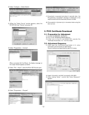
... Adjustment (1) Connect the MEMORY JIG and PC. (2) Turn on the JIG MAIN POWER SWITCH. (3) After turn on the Output window and the Download process is ended. (8) The execution of process (6) is displayed on the PC and MONITOR, execute the 'Certificate Downloader v1.4' from the screen. 5-2. Adjustment Sequence (1) After open . (2) Select 'Connection' and SET connected to RS-232C. (3) After clicking "Enter", confirm that "Enter Password:" appears. (6) Select "Programmer -> Program". - 12 - (2) Select "Configure -> Select...
... Adjustment (1) Connect the MEMORY JIG and PC. (2) Turn on the JIG MAIN POWER SWITCH. (3) After turn on the Output window and the Download process is ended. (8) The execution of process (6) is displayed on the PC and MONITOR, execute the 'Certificate Downloader v1.4' from the screen. 5-2. Adjustment Sequence (1) After open . (2) Select 'Connection' and SET connected to RS-232C. (3) After clicking "Enter", confirm that "Enter Password:" appears. (6) Select "Programmer -> Program". - 12 - (2) Select "Configure -> Select...
Service Manual
Page 13
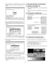
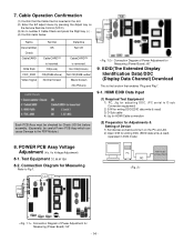
Guide Data Discharge Equipment [ In case of set quantity. (2) Enter the EZ adjust menu by pressing Adjust on the Service Remote Control (S R/C). (3) Go to number 1 Gemstar and press Enter. (4) TV set screen will begin. 6-3. Required Test Equipment (1) PC with VBI Inserter(TES3): Signal uses Cable input and set as below . [ Factory Test S/W must be used. 6-2. RS-232C (5) After clicking ENTER, the 'opens Private key' window appears and select the Private...
Guide Data Discharge Equipment [ In case of set quantity. (2) Enter the EZ adjust menu by pressing Adjust on the Service Remote Control (S R/C). (3) Go to number 1 Gemstar and press Enter. (4) TV set screen will begin. 6-3. Required Test Equipment (1) PC with VBI Inserter(TES3): Signal uses Cable input and set as below . [ Factory Test S/W must be used. 6-2. RS-232C (5) After clicking ENTER, the 'opens Private key' window appears and select the Private...
Service Manual
Page 14
... to Fig 1. Connection Diagram for Measuring Refer to the PDP Module.) Connection Diagram of Device 1) Set devices as below . OK(Lock) OK(20dB above) Normal Screen CableCARDTM is inserted. HDMI EDID Data Input (1) Required Test Equipment 1) PC, Jig for adjusting DDC. (PC serial to number 2 Cable Check and press the Right key (G ) . (4) Confirm items below and turn on the Service Remote Control (S R/C). (3) Go to D-sub Connection equipment) 2) S/W for...
... to Fig 1. Connection Diagram for Measuring Refer to the PDP Module.) Connection Diagram of Device 1) Set devices as below . OK(Lock) OK(20dB above) Normal Screen CableCARDTM is inserted. HDMI EDID Data Input (1) Required Test Equipment 1) PC, Jig for adjusting DDC. (PC serial to number 2 Cable Check and press the Right key (G ) . (4) Confirm items below and turn on the Service Remote Control (S R/C). (3) Go to D-sub Connection equipment) 2) S/W for...

Service Manual
Page 15
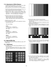
... automatic movement. (3) When the adjustment is complete, exit the adjustment mode by pressing the ADJ KEY. 11. 10. Connection Diagram of device' ) is displayed. (5) Readjust after confirming the case Pattern or adjustment condition where the adjustment errors. CA-100 Digital RGB PDP MONITOR Adjustment Pattern : 480i/1080i 60Hz HozTV31 Bar Pattern MSPG-925FA 10-3. And error massage('Component Not Connection' or 'Change Format to 480i' or 'Check...
... automatic movement. (3) When the adjustment is complete, exit the adjustment mode by pressing the ADJ KEY. 11. 10. Connection Diagram of device' ) is displayed. (5) Readjust after confirming the case Pattern or adjustment condition where the adjustment errors. CA-100 Digital RGB PDP MONITOR Adjustment Pattern : 480i/1080i 60Hz HozTV31 Bar Pattern MSPG-925FA 10-3. And error massage('Component Not Connection' or 'Change Format to 480i' or 'Check...
Service Manual
Page 16
... the signal receiving. Adjustment (1) Connection the Video Signal Generator(Master) to PDP module surface when you adjust. O Manual adjustment is complete, exit the adjustment mode by pressing the ADJ Key on the Service R/C. Adjust the Hight Light using G Gain/B Gain(Warm). (R Gain: 192, B Gain 192, R-Cut/G-Cut/B-Cut: 64 Fix.) (4) Adjust using G Gain/R Gain(Medium). If the adjustment has errors, 'Video Configuration Error' is displayed. (3) Adjust the Hight Light using R Gain/G Gain(Cool). Adjust the Hight Light using Volume...
... the signal receiving. Adjustment (1) Connection the Video Signal Generator(Master) to PDP module surface when you adjust. O Manual adjustment is complete, exit the adjustment mode by pressing the ADJ Key on the Service R/C. Adjust the Hight Light using G Gain/B Gain(Warm). (R Gain: 192, B Gain 192, R-Cut/G-Cut/B-Cut: 64 Fix.) (4) Adjust using G Gain/R Gain(Medium). If the adjustment has errors, 'Video Configuration Error' is displayed. (3) Adjust the Hight Light using R Gain/G Gain(Cool). Adjust the Hight Light using Volume...
Service Manual
Page 17
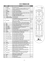
... automatically if the power is supplied to the TV. (Use the POWER key to deactivate): It should be deactivated when delivered. 3 MUTE 4 P-CHECK To activate the mute function. To adjust the volume or accurately control a specific function. Use the AV To adjust the screen voltage (automatic): key to select a function displayed on the screen. To check TV screen image easily. To select the multiple sound mode (Mono, Stereo or...
... automatically if the power is supplied to the TV. (Use the POWER key to deactivate): It should be deactivated when delivered. 3 MUTE 4 P-CHECK To activate the mute function. To adjust the volume or accurately control a specific function. Use the AV To adjust the screen voltage (automatic): key to select a function displayed on the screen. To check TV screen image easily. To select the multiple sound mode (Mono, Stereo or...
Service Manual
Page 31
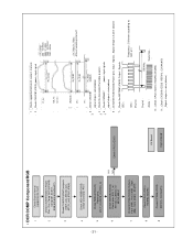
... (IC301) AV Board Digit al Bo ard 1 : _Check supported format(ref. owner's manual) 2 : _Check CXA2181(IC300) power, input signal (Y_in) : (Cb_in) : (Cr_in) : Fh_Comp < Fh_Comp> 480i : 15.75KHz 480p : 31.5Khz 1080i : 33.75KHz 720P : 45KHz (R)(B)(G) : (H) : Fh_RGB Fh_RGB < Fh_RGB, Fv_RGB> different according to format!!! (V) : 3 : _Check CXA2181 Fv_RGB outputs _signal shape s same(above) 4 : _Check the Connector(Flat cable & wafer) 5 : _Check FMS6407 power, input signals _signal shape is...
... (IC301) AV Board Digit al Bo ard 1 : _Check supported format(ref. owner's manual) 2 : _Check CXA2181(IC300) power, input signal (Y_in) : (Cb_in) : (Cr_in) : Fh_Comp < Fh_Comp> 480i : 15.75KHz 480p : 31.5Khz 1080i : 33.75KHz 720P : 45KHz (R)(B)(G) : (H) : Fh_RGB Fh_RGB < Fh_RGB, Fv_RGB> different according to format!!! (V) : 3 : _Check CXA2181 Fv_RGB outputs _signal shape s same(above) 4 : _Check the Connector(Flat cable & wafer) 5 : _Check FMS6407 power, input signals _signal shape is...

Service Manual
Page 38
... P1604 YES NO AC DETECT(P1604 #1) is red) Check Fa ns Fan(P1606), upper /sid e ( 50" : 1EA, 42" : No FAN ) Fan op erate norm ally ? NO Check Fa n wafers and c onn ector s. Replace Po wer board Norm al? And po wer off(LED is 5V HIGH ? No Replace Fans and recheck - 38 - NO Check A/V ...bo ard Mic om NO Check A/V bo ard Mic om Norm al? NO Replace A/V boa rd or digital bo ard Replace p ower board Norm al? • Protect Mode Symptom : When TV set powers on, LED i s blin ki ng in secon ...
... P1604 YES NO AC DETECT(P1604 #1) is red) Check Fa ns Fan(P1606), upper /sid e ( 50" : 1EA, 42" : No FAN ) Fan op erate norm ally ? NO Check Fa n wafers and c onn ector s. Replace Po wer board Norm al? And po wer off(LED is 5V HIGH ? No Replace Fans and recheck - 38 - NO Check A/V ...bo ard Mic om NO Check A/V bo ard Mic om Norm al? NO Replace A/V boa rd or digital bo ard Replace p ower board Norm al? • Protect Mode Symptom : When TV set powers on, LED i s blin ki ng in secon ...
Service Manual
Page 39
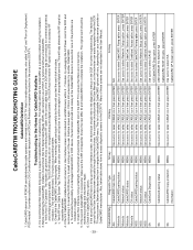
... can also connect a cable set top box to the correct cable input of the pinholes are not described in a User Interface screen (also referred to complete the installation. If this by cable operators and inserted into place. Below table describes how to select CableCARD. CableCARD Mfg ALL Motorola Motorola Motorola Mororola NDS NDS NDS SA Diagnostic Type CableCARD main menu CableCARD pairing status Network status...
... can also connect a cable set top box to the correct cable input of the pinholes are not described in a User Interface screen (also referred to complete the installation. If this by cable operators and inserted into place. Below table describes how to select CableCARD. CableCARD Mfg ALL Motorola Motorola Motorola Mororola NDS NDS NDS SA Diagnostic Type CableCARD main menu CableCARD pairing status Network status...
Service Manual
Page 40
... Band Si gnal Status, OOB Signal Status, etc) 1st key MENU 2nd key Use cursor to Noise Ratio) : higher than 12 dB is correct. a. Cable Channel List : Ready b. CableCard : Inserted c. SNR( Signal to select CABLE icon 3rd key Press button 0 (zero) 4th key Press button 0 (zero) 5th Key Press button 0 (zero) Cabl eCARD Mfg ALL - works with a or more other DCR TVs at the customer's home.
... Band Si gnal Status, OOB Signal Status, etc) 1st key MENU 2nd key Use cursor to Noise Ratio) : higher than 12 dB is correct. a. Cable Channel List : Ready b. CableCard : Inserted c. SNR( Signal to select CABLE icon 3rd key Press button 0 (zero) 4th key Press button 0 (zero) 5th Key Press button 0 (zero) Cabl eCARD Mfg ALL - works with a or more other DCR TVs at the customer's home.

Service Manual
Page 41
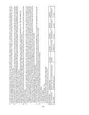
- 41 - • Audio Path RGB Audi o Compone nt 1 Compone nt 2 AV Front AV NT Tun er AT/NT Tuner HDD HDMI AUDIO TROUBLESHOOTING & BLOCK DIAGRAM AV Switch (CXA2069) L/R L/R L/R L/R Main Audi o Process or (MSP4450K) SIF L/R SIF Buffer (MC33078) Sub Audi o Process or (MSP4458G) I2S I2S ADC (CS5331A) I2S Main (LGDT3703) MUX CPLD (EPM570F256) TP I2S TP PWM Modulator (NSP2100A) AMP (TAS5122) SiI 3512 PVR SOC (LGDT1304P) HD-2 SPDIF System CPLD (EPM570T144) Front Speaker Monitor Out SPDIF Out (Optical ) MST3361 SPDIF CS8415A
- 41 - • Audio Path RGB Audi o Compone nt 1 Compone nt 2 AV Front AV NT Tun er AT/NT Tuner HDD HDMI AUDIO TROUBLESHOOTING & BLOCK DIAGRAM AV Switch (CXA2069) L/R L/R L/R L/R Main Audi o Process or (MSP4450K) SIF L/R SIF Buffer (MC33078) Sub Audi o Process or (MSP4458G) I2S I2S ADC (CS5331A) I2S Main (LGDT3703) MUX CPLD (EPM570F256) TP I2S TP PWM Modulator (NSP2100A) AMP (TAS5122) SiI 3512 PVR SOC (LGDT1304P) HD-2 SPDIF System CPLD (EPM570T144) Front Speaker Monitor Out SPDIF Out (Optical ) MST3361 SPDIF CS8415A


