Instruction Manual
Page 1
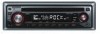
... read through this instruction manual. Model KDC-135/135CR Serial number US Residence Only Register Online Register your Kenwood dealer for information or service on the warranty card, and in the space provided below. For your new CD-receiver. KDC-135 KDC-135CR CD-RECEIVER INSTRUCTION MANUAL AMPLI-TUNER LECTEUR DE CD MODE D'EMPLOI REPRODUCTOR DE DISCOS COMPACTOS ...on the back of the unit, in the spaces designated on the product. Familiarity with installation and operation procedures will help you call upon your Kenwood product at www.Kenwoodusa.com © B64-3691-00/00 (KW)
... read through this instruction manual. Model KDC-135/135CR Serial number US Residence Only Register Online Register your Kenwood dealer for information or service on the warranty card, and in the space provided below. For your new CD-receiver. KDC-135 KDC-135CR CD-RECEIVER INSTRUCTION MANUAL AMPLI-TUNER LECTEUR DE CD MODE D'EMPLOI REPRODUCTOR DE DISCOS COMPACTOS ...on the back of the unit, in the spaces designated on the product. Familiarity with installation and operation procedures will help you call upon your Kenwood product at www.Kenwoodusa.com © B64-3691-00/00 (KW)
Instruction Manual
Page 2
... Speaker Setting Clock Display Subwoofer Output Theft Deterrent Faceplate TEL Mute Tuner features Tuning Tuning Mode Station Preset Memory Auto Memory Entry Preset Tuning CD player features Playing CD Fast Forwarding and Reversing Track Search Track Repeat Scan Play Random Play Menu system Menu System Touch Sensor Tone Manual Clock Adjustment DSI (Disabled...
... Speaker Setting Clock Display Subwoofer Output Theft Deterrent Faceplate TEL Mute Tuner features Tuning Tuning Mode Station Preset Memory Auto Memory Entry Preset Tuning CD player features Playing CD Fast Forwarding and Reversing Track Search Track Repeat Scan Play Random Play Menu system Menu System Touch Sensor Tone Manual Clock Adjustment DSI (Disabled...
Instruction Manual
Page 3
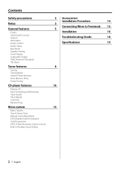
... check with your Kenwood dealer to make sure that they work to professionals. 2CAUTION To prevent damage to the machine, take the following precautions: • Make sure to ground the unit to a negative 12V DC power supply. • Do not install the unit in the CD player of precision equipment.... hard cloth or using a volatile liquid such as thinner or alcohol may be inapplicable. Use only the screws provided. If you use your Kenwood dealer. The unit returns to direct sunlight or excessive heat or humidity. Reset button Cleaning the Unit If the faceplate of the illustrations on...
... check with your Kenwood dealer to make sure that they work to professionals. 2CAUTION To prevent damage to the machine, take the following precautions: • Make sure to ground the unit to a negative 12V DC power supply. • Do not install the unit in the CD player of precision equipment.... hard cloth or using a volatile liquid such as thinner or alcohol may be inapplicable. Use only the screws provided. If you use your Kenwood dealer. The unit returns to direct sunlight or excessive heat or humidity. Reset button Cleaning the Unit If the faceplate of the illustrations on...
Instruction Manual
Page 4
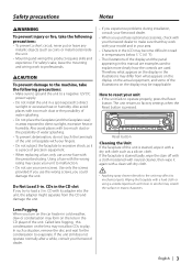
...out horizontally. • If the CD center hole or outside rim has burrs, use the CD only after removing the burrs with a ballpoint pen etc. on the CD, or use a CD with the limits for help. 4 | English Kenwood Corporation 2967-3, ISHIKAWA-MACHI, HACHIOJI-SHI TOKYO, JAPAN KENWOOD CORP. However, there is made.... been tested and found to comply with tape stuck on it is connected. • Consult the dealer or an experienced radio/TV technician for a Class B digital device, pursuant to provide reasonable protection against harmful interference in a particular installation. Handling...
...out horizontally. • If the CD center hole or outside rim has burrs, use the CD only after removing the burrs with a ballpoint pen etc. on the CD, or use a CD with the limits for help. 4 | English Kenwood Corporation 2967-3, ISHIKAWA-MACHI, HACHIOJI-SHI TOKYO, JAPAN KENWOOD CORP. However, there is made.... been tested and found to comply with tape stuck on it is connected. • Consult the dealer or an experienced radio/TV technician for a Class B digital device, pursuant to provide reasonable protection against harmful interference in a particular installation. Handling...
Instruction Manual
Page 5
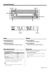
... any resistance. Turning OFF the Power Press the [SRC] button for at least 1 second. Source required Tuner CD Auxiliary input* Standby (Illumination only mode) Display "TUnE" "CD" "AUH" "STBY" * An equipment such as a portable audio player can be connected to the auxiliary input terminal using a commercially available mini-plug (3.5ø). ⁄ • Use...
... any resistance. Turning OFF the Power Press the [SRC] button for at least 1 second. Source required Tuner CD Auxiliary input* Standby (Illumination only mode) Display "TUnE" "CD" "AUH" "STBY" * An equipment such as a portable audio player can be connected to the auxiliary input terminal using a commercially available mini-plug (3.5ø). ⁄ • Use...
Instruction Manual
Page 6
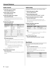
Audio Setup Setting the Sound system, such as a difference from the basic volume. • *Function of KDC-135 5 Exit Audio Setup mode Press the [VOL] knob for at least 1 second. 3 Select the Audio Setup item to adjust Press the [VOL] knob. Each time ...'s volume as Volume offset. 1 Select the source to adjust Press the [SRC] button. 2 Enter Audio Setup mode Press the [VOL] knob for different types of KDC-135 5 Exit Audio Control mode Press any button. Setting Bass Boost 1 Bass Boost 2 Bass Boost off Display "L1 BB-L" "L2 BB-L" "OFF BB-L" 6 | English Adjustment Item...
Audio Setup Setting the Sound system, such as a difference from the basic volume. • *Function of KDC-135 5 Exit Audio Setup mode Press the [VOL] knob for at least 1 second. 3 Select the Audio Setup item to adjust Press the [VOL] knob. Each time ...'s volume as Volume offset. 1 Select the source to adjust Press the [SRC] button. 2 Enter Audio Setup mode Press the [VOL] knob for different types of KDC-135 5 Exit Audio Control mode Press any button. Setting Bass Boost 1 Bass Boost 2 Bass Boost off Display "L1 BB-L" "L2 BB-L" "OFF BB-L" 6 | English Adjustment Item...
Instruction Manual
Page 7
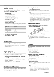
...the table below. Also avoid places with you push the knob, Subwoofer output switches ON and OFF. Theft Deterrent Faceplate The faceplate of KDC-135CR) • Do not expose the faceplate (and the faceplate case) to use the TEL Mute feature, you to direct sunlight or... its faceplate case while detached. (Faceplate case: Accessory of the unit can be detached and taken with too much dust or the possibility of KDC-135 Subwoofer Output Turning the Subwoofer output ON or OFF. Removing the Faceplate Press the Release button. When it clicks. The audio system pauses. Function...
...the table below. Also avoid places with you push the knob, Subwoofer output switches ON and OFF. Theft Deterrent Faceplate The faceplate of KDC-135CR) • Do not expose the faceplate (and the faceplate case) to use the TEL Mute feature, you to direct sunlight or... its faceplate case while detached. (Faceplate case: Accessory of the unit can be detached and taken with too much dust or the possibility of KDC-135 Subwoofer Output Turning the Subwoofer output ON or OFF. Removing the Faceplate Press the Release button. When it clicks. The audio system pauses. Function...
Instruction Manual
Page 8
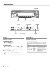
Press the [AUTO] button. Tuning mode Display Operation Auto seek "AUTO 1" Automatic search for a station. Tuning Mode Choose the tuning mode. Manual - Normal manual tuning control. 8 | English Each time you push the knob toward [FM], it switches between the modes shown in indicator the Preset memory. Select the "TUnE" display. 2 Select the band Push the Control knob towards [4] or [¢]. ⁄ • During reception of the stations in the table below. Each time you press the button, the Tuning mode alternates between the FM1, FM2, and FM3 bands. 3 Tune...
Press the [AUTO] button. Tuning mode Display Operation Auto seek "AUTO 1" Automatic search for a station. Tuning Mode Choose the tuning mode. Manual - Normal manual tuning control. 8 | English Each time you push the knob toward [FM], it switches between the modes shown in indicator the Preset memory. Select the "TUnE" display. 2 Select the band Push the Control knob towards [4] or [¢]. ⁄ • During reception of the stations in the table below. Each time you press the button, the Tuning mode alternates between the FM1, FM2, and FM3 bands. 3 Tune...
Instruction Manual
Page 9
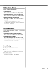
On each band, 1 station can be put in the memory. 1 Select the band Push the Control knob towards [FM] or [AM]. 2 Open Auto Memory Entry Press the [AME] button for at least 2 seconds. Auto Memory Entry Putting stations with good reception in the memory Press the desired [1] - [6] button for at least 2 seconds. Station Preset Memory Putting a station in the memory. 1 Select the band Push the Control knob towards [FM] or [AM]. 2 Select the frequency to put in the memory Push the Control knob towards [4] or [¢]. 3 Put the frequency in the memory automatically. 1 Select the band ...
On each band, 1 station can be put in the memory. 1 Select the band Push the Control knob towards [FM] or [AM]. 2 Open Auto Memory Entry Press the [AME] button for at least 2 seconds. Auto Memory Entry Putting stations with good reception in the memory Press the desired [1] - [6] button for at least 2 seconds. Station Preset Memory Putting a station in the memory. 1 Select the band Push the Control knob towards [FM] or [AM]. 2 Select the frequency to put in the memory Push the Control knob towards [4] or [¢]. 3 Put the frequency in the memory automatically. 1 Select the band ...
Instruction Manual
Page 10
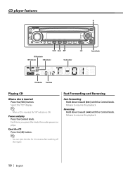
...Fast Forwarding Hold down toward [¢] with the Control knob. Each time you press the knob, the audio pauses or plays. Eject the CD Press the [0] button. ⁄ • You can eject the disc for 10 minutes after switching off the engine. Release to resume... Control knob. Pause and play Press the Control knob. CD player features 4$"/ 3%. 3&1 43$ RDM indicator REP indicator SCN indicator Track number Control knob IN indicator Track time Playing CD When a disc is ON. Select the "CD" display. ⁄ • When a CD is inserted, the "IN" indicator is inserted Press the...
...Fast Forwarding Hold down toward [¢] with the Control knob. Each time you press the knob, the audio pauses or plays. Eject the CD Press the [0] button. ⁄ • You can eject the disc for 10 minutes after switching off the engine. Release to resume... Control knob. Pause and play Press the Control knob. CD player features 4$"/ 3%. 3&1 43$ RDM indicator REP indicator SCN indicator Track number Control knob IN indicator Track time Playing CD When a disc is ON. Select the "CD" display. ⁄ • When a CD is inserted, the "IN" indicator is inserted Press the...
Instruction Manual
Page 11
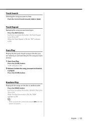
Random Play Playing all the songs on the disc you are listening to hear. 1 Start Scan Play Press the [SCAN] button. Track Search Selecting the song you press the button, the Track Repeat turns ON or OFF. Each time you want to hear. English | 11 Press the [RDM] button. When the Track Repeat is ON, the "REP" indicator is played Press the [SCAN] button. Scan Play Playing the first part of each song on the disc in random order. Each time you want to listen to and searching for the song you press the button, Random Play turns ON or OFF. "SCN" indicator is ON. 2 Release...
Random Play Playing all the songs on the disc you are listening to hear. 1 Start Scan Play Press the [SCAN] button. Track Search Selecting the song you press the button, the Track Repeat turns ON or OFF. Each time you want to hear. English | 11 Press the [RDM] button. When the Track Repeat is ON, the "REP" indicator is played Press the [SCAN] button. Scan Play Playing the first part of each song on the disc in random order. Each time you want to listen to and searching for the song you press the button, Random Play turns ON or OFF. "SCN" indicator is ON. 2 Release...
Instruction Manual
Page 12
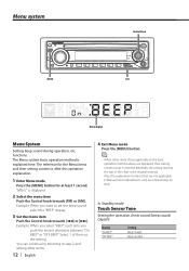
functions. Display "On BEEP" "OFF BEEP" Setting Beep is explained here. You can continue by step. Example: When you select "BEEP", each time you want to the basic operation method above are displayed, their setting content is after this operation explanation. 1 Enter Menu mode Press the [MENU] button for items that are not applicable ( etc.) are entered step by returning to step 2 and setting other items. 12 | English 4 Exit Menu mode Press the [MENU] button. ⁄ • When other items those applicable to set the beep sound select the "BEEP" display. 3 Set the menu ...
functions. Display "On BEEP" "OFF BEEP" Setting Beep is explained here. You can continue by step. Example: When you select "BEEP", each time you want to the basic operation method above are displayed, their setting content is after this operation explanation. 1 Enter Menu mode Press the [MENU] button for items that are not applicable ( etc.) are entered step by returning to step 2 and setting other items. 12 | English 4 Exit Menu mode Press the [MENU] button. ⁄ • When other items those applicable to set the beep sound select the "BEEP" display. 3 Set the menu ...
Instruction Manual
Page 13
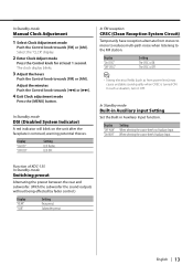
Display "On CRSC" "OFF CRSC" Setting The CRSC is removed, warning potential thieves. Function of KDC-135 In Standby mode Switching preout Alternating the preout between the rear and subwoofer. (With the subwoofer the sound outputs without being effected by fader control.) ...
Display "On CRSC" "OFF CRSC" Setting The CRSC is removed, warning potential thieves. Function of KDC-135 In Standby mode Switching preout Alternating the preout between the rear and subwoofer. (With the subwoofer the sound outputs without being effected by fader control.) ...
Instruction Manual
Page 14
battery. 2. Connect the wiring harness wires in your car's ignition does not have been activated. Connect the wiring harness connector to both the rear output terminals (do not connect the - battery. 8. connector to a rear output terminal. • After the unit is ON, but will not hit the lid when closing and opening. • If the fuse blows, first make sure to install the unit so that the faceplate will be OFF immediately), the speaker wire may have a short-circuit or touched the chassis of the unconnected wires or the terminals. • Connect the speaker wires correctly ...
battery. 2. Connect the wiring harness wires in your car's ignition does not have been activated. Connect the wiring harness connector to both the rear output terminals (do not connect the - battery. 8. connector to a rear output terminal. • After the unit is ON, but will not hit the lid when closing and opening. • If the fuse blows, first make sure to install the unit so that the faceplate will be OFF immediately), the speaker wire may have a short-circuit or touched the chassis of the unconnected wires or the terminals. • Connect the speaker wires correctly ...
Instruction Manual
Page 15
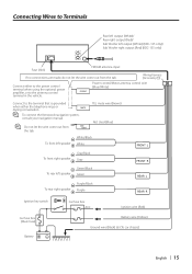
...To front left speaker White/Black White FRONT L To front right speaker Gray/Black Gray To rear left output (White) (KDC-135 only)/ Sub Woofer right output (Red) (KDC-135 only) Fuse (10A) FM/AM antenna input If no connections are made, do not let the wire come out from... the tab. Wiring harness (Accessory1) Connect either the telephone rings or MUTE during conversation. ⁄ To connect the Kenwood navigation system, consult your navigation...
...To front left speaker White/Black White FRONT L To front right speaker Gray/Black Gray To rear left output (White) (KDC-135 only)/ Sub Woofer right output (Red) (KDC-135 only) Fuse (10A) FM/AM antenna input If no connections are made, do not let the wire come out from... the tab. Wiring harness (Accessory1) Connect either the telephone rings or MUTE during conversation. ⁄ To connect the Kenwood navigation system, consult your navigation...
Instruction Manual
Page 16
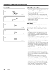
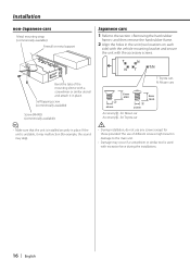
Accessory3...for Nissan car Accessory4...for Toyota car ¤ • During installation, do not use of the mounting sleeve with the accessory screws. Self-tapping screw (commercially available) Screw (M4X8) (commercially available) ⁄ • Make sure that the unit is unstable, it in place. T N T/N NT T: Toyota cars N: Nissan cars 3 ø5mm 8 mm MAX. 4 ø5mm 8mm MAX. Japanese cars 1 Refer to the main unit. • Damage may skip). Installation non-Japanese cars Metal mounting strap (commercially available) Firewall or metal support Bend the tabs of ...
Accessory3...for Nissan car Accessory4...for Toyota car ¤ • During installation, do not use of the mounting sleeve with the accessory screws. Self-tapping screw (commercially available) Screw (M4X8) (commercially available) ⁄ • Make sure that the unit is unstable, it in place. T N T/N NT T: Toyota cars N: Nissan cars 3 ø5mm 8 mm MAX. 4 ø5mm 8mm MAX. Japanese cars 1 Refer to the main unit. • Damage may skip). Installation non-Japanese cars Metal mounting strap (commercially available) Firewall or metal support Bend the tabs of ...
Instruction Manual
Page 17
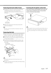
English | 17 Removing the hard rubber frame 1 Engage the catch pins on the removal tool and remove the two locks on the Unit If you screw them in the figure. Upper the frame and pull it does not fall off, screw in the provided screws in the holes shown below. Accessory5 Lock Catch Accessory2 Removal tool 2 When the upper level is removed, remove the lower two locations. ⁄ • The frame can be removed from the catch pins on the removal tool. 5 Pull the unit all the way out with your hands, being careful not to the section and then remove the hard rubber frame. 2 Remove ...
English | 17 Removing the hard rubber frame 1 Engage the catch pins on the removal tool and remove the two locks on the Unit If you screw them in the figure. Upper the frame and pull it does not fall off, screw in the provided screws in the holes shown below. Accessory5 Lock Catch Accessory2 Removal tool 2 When the upper level is removed, remove the lower two locations. ⁄ • The frame can be removed from the catch pins on the removal tool. 5 Pull the unit all the way out with your hands, being careful not to the section and then remove the hard rubber frame. 2 Remove ...
Instruction Manual
Page 18
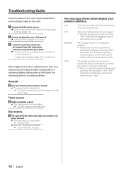
...in your unit may be disabled by some reason. ➪ Press the reset button on . ☞ (page 13) ! The CD is not operating properly. ➪ Reinsert the CD. IN (Blink): The CD player section is scratched a lot. Cannot display the user of System Q. ▲ (page 6) is not set. ! • Cannot...consult your nearest service center. Disc source ? Radio reception is poor. ✔ The car antenna is not set up the subwoofer. • No output from the preout jack. E-04: The CD is not turned on the unit. If the CD cannot be ejected or the display continues to subwoofer...
...in your unit may be disabled by some reason. ➪ Press the reset button on . ☞ (page 13) ! The CD is not operating properly. ➪ Reinsert the CD. IN (Blink): The CD player section is scratched a lot. Cannot display the user of System Q. ▲ (page 6) is not set. ! • Cannot...consult your nearest service center. Disc source ? Radio reception is poor. ✔ The car antenna is not set up the subwoofer. • No output from the preout jack. E-04: The CD is not turned on the unit. If the CD cannot be ejected or the display continues to subwoofer...
Instruction Manual
Page 19
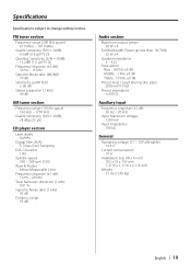
... Stereo separation (1 kHz) : 40 dB AM tuner section Frequency range (10 kHz space) : 530 kHz - 1700 kHz Usable sensitivity (S/N = 20dB) : 28 dBμ (25 μV) CD player section Laser diode : GaAlAs Digital filter (D/A) : 8 Times Over Sampling D/A Converter : 1 Bit Spindle speed : 500 - 200 rpm (CLV) Wow & Flutter : Below Measurable Limit Frequency response (±...
... Stereo separation (1 kHz) : 40 dB AM tuner section Frequency range (10 kHz space) : 530 kHz - 1700 kHz Usable sensitivity (S/N = 20dB) : 28 dBμ (25 μV) CD player section Laser diode : GaAlAs Digital filter (D/A) : 8 Times Over Sampling D/A Converter : 1 Bit Spindle speed : 500 - 200 rpm (CLV) Wow & Flutter : Below Measurable Limit Frequency response (±...