User Guide
Page 1
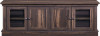
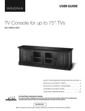
USER GUIDE TV Console for up to 75" TVs NS-HWG1965 SAFETY INFORMATION AND SPECIFICATIONS..2 PACKAGE CONTENTS: PARTS 3 PACKAGE CONTENTS: HARDWARE 4 ASSEMBLY INSTRUCTIONS 6 CARE AND MAINTENANCE 22 On-line Video Instruction Guides Go to www.guides.sellpoints.com to view step-by-step instructional videos for assembling and installing your new product, please read these instructions to prevent any damage. Enter the following product number on the website. NS-HWG1965 Before using your product.
USER GUIDE TV Console for up to 75" TVs NS-HWG1965 SAFETY INFORMATION AND SPECIFICATIONS..2 PACKAGE CONTENTS: PARTS 3 PACKAGE CONTENTS: HARDWARE 4 ASSEMBLY INSTRUCTIONS 6 CARE AND MAINTENANCE 22 On-line Video Instruction Guides Go to www.guides.sellpoints.com to view step-by-step instructional videos for assembling and installing your new product, please read these instructions to prevent any damage. Enter the following product number on the website. NS-HWG1965 Before using your product.

User Guide
Page 2
... lbs (151.9 kg) Maximum top panel weight: 135 lbs (61.2 kg) Maximum shelf weight: 50 lbs (22.6 kg) Maximum TV weight: 135 lbs (61.2 kg) Maximum screen size: 75" diag. The base of the top panel. NS-HWG1965 SAFETY INFORMATION AND SPECIFICATIONS CAUTION: The console's top work surface is designed for more details. See instructions for use with a product weighing no more than 135...
... lbs (151.9 kg) Maximum top panel weight: 135 lbs (61.2 kg) Maximum shelf weight: 50 lbs (22.6 kg) Maximum TV weight: 135 lbs (61.2 kg) Maximum screen size: 75" diag. The base of the top panel. NS-HWG1965 SAFETY INFORMATION AND SPECIFICATIONS CAUTION: The console's top work surface is designed for more details. See instructions for use with a product weighing no more than 135...

User Guide
Page 3
Power drill A Top panel (1) Note: Keep the stopper template attached to assemble your new TV stand. Tools needed: TV Console for up to 75" TVs Hammer Phillips screwdriver Rubber mallet 3/8" drill bit Pliers PACKAGE CONTENTS: PARTS Make sure that you have all the parts necessary to the top panel. B Left side panel (1) C Right side panel (1) D Partition panel (1) F Front skirting (1) H Left skirting (1) I Right skirting (1) E Bottom shelf (1) G Back skirting (1) J Back panel (1) K Adjustable shelf (2) L Door (4) M Wood door panel (4) www.insigniaproducts.com 3
Power drill A Top panel (1) Note: Keep the stopper template attached to assemble your new TV stand. Tools needed: TV Console for up to 75" TVs Hammer Phillips screwdriver Rubber mallet 3/8" drill bit Pliers PACKAGE CONTENTS: PARTS Make sure that you have all the parts necessary to the top panel. B Left side panel (1) C Right side panel (1) D Partition panel (1) F Front skirting (1) H Left skirting (1) I Right skirting (1) E Bottom shelf (1) G Back skirting (1) J Back panel (1) K Adjustable shelf (2) L Door (4) M Wood door panel (4) www.insigniaproducts.com 3

User Guide
Page 4
...X Knob NS-HWG1965 Qty. 4 P Cam pin 22 Y Knob bolt 4 Q Cam lock 22 Z Corner connector 2 Screw R M4 x 50 mm 6 AA Floor leveler 2 S Flat head screw M3.5 x 15 mm 12 BB CC Washer head screw T M3.5 x 15 mm 22 DD U Door stopper 2 EE V Cam lock cover 6 FF Shelf support W 8... GG Stopper 2 Glue 1 Bumper 4 Large cam lock cover 4 Touch-up pen 1 Tipping restraint hardware kit 2 1 2 3 4in 10 20 30 40 50 60 70 80 90 100mm 4 www.insigniaproducts.com Make sure that you have all the hardware necessary to assemble your new TV stand...
...X Knob NS-HWG1965 Qty. 4 P Cam pin 22 Y Knob bolt 4 Q Cam lock 22 Z Corner connector 2 Screw R M4 x 50 mm 6 AA Floor leveler 2 S Flat head screw M3.5 x 15 mm 12 BB CC Washer head screw T M3.5 x 15 mm 22 DD U Door stopper 2 EE V Cam lock cover 6 FF Shelf support W 8... GG Stopper 2 Glue 1 Bumper 4 Large cam lock cover 4 Touch-up pen 1 Tipping restraint hardware kit 2 1 2 3 4in 10 20 30 40 50 60 70 80 90 100mm 4 www.insigniaproducts.com Make sure that you have all the hardware necessary to assemble your new TV stand...

User Guide
Page 5
TV Console for up to 75" TVs INSTALLATION TIPS Gluing wood dowels (N) When using a wood dowel (N), put one drop of glue (CC) in place. 1 2 GLUE 3 4 FINAL X Locking cam pins (P) and cam locks (Q) 1 One end of a cam pin (P) is not ... hole and make sure that it screws into the cross slot of the cam pin (P) through the hole in the part being used and into the cam lock hole, then rotate the cam lock (Q) clockwise with a rubber mallet to conceal. Before you insert the wood dowel (N). Cam pin PANEL Pre-drilled hole Cam lock...
TV Console for up to 75" TVs INSTALLATION TIPS Gluing wood dowels (N) When using a wood dowel (N), put one drop of glue (CC) in place. 1 2 GLUE 3 4 FINAL X Locking cam pins (P) and cam locks (Q) 1 One end of a cam pin (P) is not ... hole and make sure that it screws into the cross slot of the cam pin (P) through the hole in the part being used and into the cam lock hole, then rotate the cam lock (Q) clockwise with a rubber mallet to conceal. Before you insert the wood dowel (N). Cam pin PANEL Pre-drilled hole Cam lock...
User Guide
Page 6
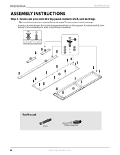
NS-HWG1965 ASSEMBLY INSTRUCTIONS Step 1: Screw cam pins onto the top panel, bottom shelf, and skirtings Tip: Assemble your stand on a carpeted floor or the empty TV stand carton to avoid scratching it. • Securely screw the cam pins (P) into the designated small holes on the top panel (A), bottom shelf (E), front skirting (F) and side skirtings (H and I) using a Phillips screwdriver. You'll need: P (22) Phillips screwdriver 6 www.insigniaproducts.com
NS-HWG1965 ASSEMBLY INSTRUCTIONS Step 1: Screw cam pins onto the top panel, bottom shelf, and skirtings Tip: Assemble your stand on a carpeted floor or the empty TV stand carton to avoid scratching it. • Securely screw the cam pins (P) into the designated small holes on the top panel (A), bottom shelf (E), front skirting (F) and side skirtings (H and I) using a Phillips screwdriver. You'll need: P (22) Phillips screwdriver 6 www.insigniaproducts.com
User Guide
Page 8
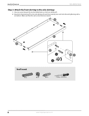
NS-HWG1965 Step 3: Attach the front skirting to the side skirtings 1 Glue two wood dowels (N) into the drilled holes on the front skirting (F). 2 Attach the front skirting (F) to the side skirtings (H and I) by inserting two cam locks (Q) and tightening with a screwdriver. Make sure that the cam screw holes face inward. You'll need: N (2) Q (2) CC (1) Phillips screwdriver 8 www.insigniaproducts.com
NS-HWG1965 Step 3: Attach the front skirting to the side skirtings 1 Glue two wood dowels (N) into the drilled holes on the front skirting (F). 2 Attach the front skirting (F) to the side skirtings (H and I) by inserting two cam locks (Q) and tightening with a screwdriver. Make sure that the cam screw holes face inward. You'll need: N (2) Q (2) CC (1) Phillips screwdriver 8 www.insigniaproducts.com
User Guide
Page 10
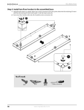
NS-HWG1965 Step 5: Install two floor levelers to the assembled base 1 Using the pilot holes as a guide, fasten two corner connectors (Z) to the joints where the front skirting (F) meet with the side skirtings (H and I) with eight 15 mm flat head screws (S). 2 Screw two floor levelers (AA) onto the installed corner connectors (Z). AA You'll need: S (8) Z (2) AA (2) Phillips screwdriver 10 www.insigniaproducts.com
NS-HWG1965 Step 5: Install two floor levelers to the assembled base 1 Using the pilot holes as a guide, fasten two corner connectors (Z) to the joints where the front skirting (F) meet with the side skirtings (H and I) with eight 15 mm flat head screws (S). 2 Screw two floor levelers (AA) onto the installed corner connectors (Z). AA You'll need: S (8) Z (2) AA (2) Phillips screwdriver 10 www.insigniaproducts.com
User Guide
Page 11
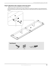
You'll need: S (4) Phillips screwdriver U (2) www.insigniaproducts.com 11 Make sure that the right angle sides of the stoppers face the front of the unit. TV Console for up to 75" TVs Step 6: Attach two door stoppers to the top panel Note: Keep the stopper template attached to the top panel (A). • Using the pilot holes as a guide, attach two door stoppers (U) onto the front supports on the top panel (A) with two 15 mm flat head screws (S) per stopper.
You'll need: S (4) Phillips screwdriver U (2) www.insigniaproducts.com 11 Make sure that the right angle sides of the stoppers face the front of the unit. TV Console for up to 75" TVs Step 6: Attach two door stoppers to the top panel Note: Keep the stopper template attached to the top panel (A). • Using the pilot holes as a guide, attach two door stoppers (U) onto the front supports on the top panel (A) with two 15 mm flat head screws (S) per stopper.
User Guide
Page 12
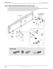
NS-HWG1965 Step 7: Align and attach the side panels to the top panel 1 Glue two wood dowels (N) into the holes on the opposite end. Door stopper Door hinge mounts point towards the front of the left side panel (B). 2 Attach the left side panel to attach the right side panel (C) on the top edge of the unit You'll need: N (4) Q (4) CC (1) Phillips screwdriver 12 www.insigniaproducts.com Make sure that the door hinge mounts are on the same side as the door stoppers. 3 Repeat this process to the top panel (A) by inserting two cam locks (Q) and tightening with a screwdriver.
NS-HWG1965 Step 7: Align and attach the side panels to the top panel 1 Glue two wood dowels (N) into the holes on the opposite end. Door stopper Door hinge mounts point towards the front of the left side panel (B). 2 Attach the left side panel to attach the right side panel (C) on the top edge of the unit You'll need: N (4) Q (4) CC (1) Phillips screwdriver 12 www.insigniaproducts.com Make sure that the door hinge mounts are on the same side as the door stoppers. 3 Repeat this process to the top panel (A) by inserting two cam locks (Q) and tightening with a screwdriver.
User Guide
Page 14
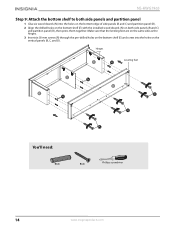
... bottom shelf (E) and screw into the holes on the bottom edge of side panels (B and C) and partition panel (D). 2 Align the drilled holes on the bottom shelf (E) with the installed wood dowels (N) on the vertical panels (B, C, and D). Hinges Leveling feet You'll need: N (6) R (6) Phillips screwdriver 14 www.insigniaproducts.com NS-HWG1965 Step 9: Attach the bottom shelf to both side panels and partition panel...
... bottom shelf (E) and screw into the holes on the bottom edge of side panels (B and C) and partition panel (D). 2 Align the drilled holes on the bottom shelf (E) with the installed wood dowels (N) on the vertical panels (B, C, and D). Hinges Leveling feet You'll need: N (6) R (6) Phillips screwdriver 14 www.insigniaproducts.com NS-HWG1965 Step 9: Attach the bottom shelf to both side panels and partition panel...

User Guide
Page 15
... the unit square. 2 Turn the assembled unit over so that all cam locks and screws. Make sure that its holes with the pilot holes along the edges of the assembled unit. 4 Use the washer head screws (T) to secure the back panel to the assembled console frame 1 Go back and tighten all the parts are tight and there are...
... the unit square. 2 Turn the assembled unit over so that all cam locks and screws. Make sure that its holes with the pilot holes along the edges of the assembled unit. 4 Use the washer head screws (T) to secure the back panel to the assembled console frame 1 Go back and tighten all the parts are tight and there are...
User Guide
Page 16
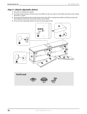
NS-HWG1965 Step 11: Attach adjustable shelves 1 Stand the assembled unit upright. 2 Insert the small and large cam lock covers (V and EE) into the cross slots on the visible cam locks on the vertical panels (B, C, and D). 3 Insert eight shelf supports (W) into the holes in the sides of the compartments. EE You'll need: V (6) EE (4) W (8) 16 www.insigniaproducts.com Make sure that you place the shelf supports at the same level so the shelves are not tilted. 4 Tilt and rest the adjustable shelves (K) onto the shelf supports (W).
NS-HWG1965 Step 11: Attach adjustable shelves 1 Stand the assembled unit upright. 2 Insert the small and large cam lock covers (V and EE) into the cross slots on the visible cam locks on the vertical panels (B, C, and D). 3 Insert eight shelf supports (W) into the holes in the sides of the compartments. EE You'll need: V (6) EE (4) W (8) 16 www.insigniaproducts.com Make sure that you place the shelf supports at the same level so the shelves are not tilted. 4 Tilt and rest the adjustable shelves (K) onto the shelf supports (W).

User Guide
Page 17
Tip: If you need to remove a door, press the release lever on the end of the hinge arm X (4) Y (4) Phillips screwdriver www.insigniaproducts.com 17 B Slide the back hooks (on how to assemble the hinges, go to www.guides.sellpoints.com to make sure they are ...panel (C) by -step instructional videos. If necessary, adjust the screws on the hinge arm for up to 75" TVs Step 12: Attach doors to the vertical panels 1 Push the knob bolts (Y) through the inside of each door (L), then screw on the ends of the door (L) to left side panel (B) and partition panel (D). Slot Hooks Mounting base...
Tip: If you need to remove a door, press the release lever on the end of the hinge arm X (4) Y (4) Phillips screwdriver www.insigniaproducts.com 17 B Slide the back hooks (on how to assemble the hinges, go to www.guides.sellpoints.com to make sure they are ...panel (C) by -step instructional videos. If necessary, adjust the screws on the hinge arm for up to 75" TVs Step 12: Attach doors to the vertical panels 1 Push the knob bolts (Y) through the inside of each door (L), then screw on the ends of the door (L) to left side panel (B) and partition panel (D). Slot Hooks Mounting base...

User Guide
Page 18
DD DD You'll need: DD (4) 18 www.insigniaproducts.com NS-HWG1965 Step 13: Attach the bumpers to the door stoppers • Peel two bumpers (DD) from the bumper card and attach one to each door stopper (U) where it will contact the door (L).
DD DD You'll need: DD (4) 18 www.insigniaproducts.com NS-HWG1965 Step 13: Attach the bumpers to the door stoppers • Peel two bumpers (DD) from the bumper card and attach one to each door stopper (U) where it will contact the door (L).

User Guide
Page 19
If your stand. Press down on the stopper (BB) to help adhesion. 4 Repeat this process to remove the stopper template. 2 Align the template at the position where one base: 1 Remove the paper backing from tipping, you must follow these instructions if you place a TV on the top panel (A). TV Console ...for up to 75" TVs Step 14: Attach the stopper to "Step 15: Change the door panel" on page 20. Otherwise, skip...
If your stand. Press down on the stopper (BB) to help adhesion. 4 Repeat this process to remove the stopper template. 2 Align the template at the position where one base: 1 Remove the paper backing from tipping, you must follow these instructions if you place a TV on the top panel (A). TV Console ...for up to 75" TVs Step 14: Attach the stopper to "Step 15: Change the door panel" on page 20. Otherwise, skip...
User Guide
Page 20
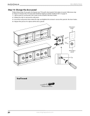
NS-HWG1965 Step 15: Change the door panel Follow these steps if you want to change your TV stand's door panels from glass to replace all the door panels. Otherwise, skip to "Step 16: Position the TV stand and install the tipping restraint hardware kit" on page 21. 1 Open a door (L) and loosen the screws on the inside of the door frame. 2 Rotate...
NS-HWG1965 Step 15: Change the door panel Follow these steps if you want to change your TV stand's door panels from glass to replace all the door panels. Otherwise, skip to "Step 16: Position the TV stand and install the tipping restraint hardware kit" on page 21. 1 Open a door (L) and loosen the screws on the inside of the door frame. 2 Rotate...

User Guide
Page 21
... Metal Steel cable bracket Long screw You'll need: Leveling feet GG (2) Power drill Phillips screwdriver 3/8" drill bit Rubber mallet www.insigniaproducts.com 21 TV Console for up to 75" TVs Step 16: Position the TV stand and install the tipping restraint hardware kit 1 Position the assembled stand against the wall where you plan to use it. 2 Adjust the leveling feet...
... Metal Steel cable bracket Long screw You'll need: Leveling feet GG (2) Power drill Phillips screwdriver 3/8" drill bit Rubber mallet www.insigniaproducts.com 21 TV Console for up to 75" TVs Step 16: Position the TV stand and install the tipping restraint hardware kit 1 Position the assembled stand against the wall where you plan to use it. 2 Adjust the leveling feet...
User Guide
Page 22
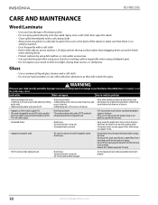
NS-HWG1965 CARE AND MAINTENANCE Wood/Laminate • Use your favorite type of injury. • Top-heavy furniture can tip over. • Overloaded shelves can break. • Never exceed the weight limits shown in the instructions. • Work from the bottom to the top when loading shelves. • The bottom shelves can only support 50 lbs. Children...
NS-HWG1965 CARE AND MAINTENANCE Wood/Laminate • Use your favorite type of injury. • Top-heavy furniture can tip over. • Overloaded shelves can break. • Never exceed the weight limits shown in the instructions. • Work from the bottom to the top when loading shelves. • The bottom shelves can only support 50 lbs. Children...
User Guide
Page 23
... Best Buy and its sole option): (1) repair the Product with new or rebuilt comparable products or parts. If you must be purchased in the county where the original purchase was made. THIS WARRANTY GIVES YOU SPECIFIC LEGAL RIGHTS, AND YOU MAY ALSO HAVE OTHER RIGHTS, WHICH VARY FROM STATE TO STATE OR PROVINCE TO PROVINCE. If service of...
... Best Buy and its sole option): (1) repair the Product with new or rebuilt comparable products or parts. If you must be purchased in the county where the original purchase was made. THIS WARRANTY GIVES YOU SPECIFIC LEGAL RIGHTS, AND YOU MAY ALSO HAVE OTHER RIGHTS, WHICH VARY FROM STATE TO STATE OR PROVINCE TO PROVINCE. If service of...


