User Guide
Page 1
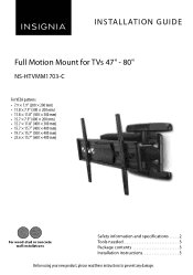
INSTALLATION GUIDE Full Motion Mount for TVs 47" - 80" NS-HTVMM1703-C For VESA patterns: • 7.9 × 7.9" (200 × 200 mm) • 11.8 × 7.9" (300 × 200 mm) • 11.8 × 11.8" (300 × 300 mm) • 15.7 × ... × 400 mm) • 19.7 × 15.7" (500 × 400 mm) • 23.6 × 15.7" (600 × 400 mm) For wood-stud or concrete wall installations Safety information and specifications . . . . . 2 Tools needed 3 Package contents 3 Installation instructions 5 Before using your new product, please read these instructions to prevent any damage.
INSTALLATION GUIDE Full Motion Mount for TVs 47" - 80" NS-HTVMM1703-C For VESA patterns: • 7.9 × 7.9" (200 × 200 mm) • 11.8 × 7.9" (300 × 200 mm) • 11.8 × 11.8" (300 × 300 mm) • 15.7 × ... × 400 mm) • 19.7 × 15.7" (500 × 400 mm) • 23.6 × 15.7" (600 × 400 mm) For wood-stud or concrete wall installations Safety information and specifications . . . . . 2 Tools needed 3 Package contents 3 Installation instructions 5 Before using your new product, please read these instructions to prevent any damage.
User Guide
Page 2
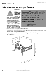
... could be capable of supporting five times the weight of your TV must be a choking hazard if swallowed. Keep these directions, or have doubts about the safety of your TV and wall mount combined. NS-HTVMM1703-C Safety information and specifications IMPORTANT SAFETY INSTRUCTIONS Maximum TV weight: 110 lbs. (50 kg) - diagonal INSTRUCTIONS CAUTION: Do Overall dimensions (H × W ): not use this product for any...
... could be capable of supporting five times the weight of your TV must be a choking hazard if swallowed. Keep these directions, or have doubts about the safety of your TV and wall mount combined. NS-HTVMM1703-C Safety information and specifications IMPORTANT SAFETY INSTRUCTIONS Maximum TV weight: 110 lbs. (50 kg) - diagonal INSTRUCTIONS CAUTION: Do Overall dimensions (H × W ): not use this product for any...

User Guide
Page 3
Full Motion Mount for TVs 47" - 80" Tools needed You will need the following tools to assemble your new TV wall mount: ardware Edge-to-edge Pencil stud finder Measuring tape Drill Tape Phillips screwdriver Hammer 3/16 in. (5 mm) wood drill bit (for wood stud wall) OR 3/8 in. (10 mm) masonry drill bit (for concrete wall) Package contents Make sure that you have all the hardware necessary to assemble your new TV wall mount: Wall Mount (1) TV Brackets (2) Wall Plate Template (1) www.insigniaproducts.com 3
Full Motion Mount for TVs 47" - 80" Tools needed You will need the following tools to assemble your new TV wall mount: ardware Edge-to-edge Pencil stud finder Measuring tape Drill Tape Phillips screwdriver Hammer 3/16 in. (5 mm) wood drill bit (for wood stud wall) OR 3/8 in. (10 mm) masonry drill bit (for concrete wall) Package contents Make sure that you have all the hardware necessary to assemble your new TV wall mount: Wall Mount (1) TV Brackets (2) Wall Plate Template (1) www.insigniaproducts.com 3
User Guide
Page 4
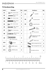
... 4 4 B2 4 4 B3 M6 × 25 mm screw 4 M8 × 16 mm screw 4 A8 M8 × 25 mm screw 4 A9 A10 A11 4 M8 × 50 mm screw Spacer 4 M4/M5 washer 4 A12 M6/M8 washer 4 NS-HTVMM1703-C Hardware Qty. Lag bolts 6 Concrete anchor 6 Lag bolt washer 6 Allen 1 wrench Box wrench 1 Magnetic removable bubble level 1 Plastic cover 2 Cable management clip...
... 4 4 B2 4 4 B3 M6 × 25 mm screw 4 M8 × 16 mm screw 4 A8 M8 × 25 mm screw 4 A9 A10 A11 4 M8 × 50 mm screw Spacer 4 M4/M5 washer 4 A12 M6/M8 washer 4 NS-HTVMM1703-C Hardware Qty. Lag bolts 6 Concrete anchor 6 Lag bolt washer 6 Allen 1 wrench Box wrench 1 Magnetic removable bubble level 1 Plastic cover 2 Cable management clip...
User Guide
Page 5
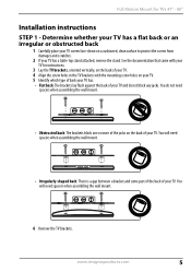
... the screw holes in the TV brackets with your TV for TVs 47" - 80" Installation instructions STEP 1 - You will need spacers when assembling the wall mount. • Obstructed back: The brackets block one or more of the jacks on a cushioned, clean surface to protect the screen from damages and scratches. 2 If your TV has a table-top stand attached, remove the stand. Determine whether...
... the screw holes in the TV brackets with your TV for TVs 47" - 80" Installation instructions STEP 1 - You will need spacers when assembling the wall mount. • Obstructed back: The brackets block one or more of the jacks on a cushioned, clean surface to protect the screen from damages and scratches. 2 If your TV has a table-top stand attached, remove the stand. Determine whether...
User Guide
Page 6
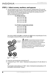
... screws that is too long short 2 Remove the screws from the mount. Option 2: Attaching the mounting hardware to "STEP 3 - NS-HTVMM1703-C STEP 2 - Screw is too Screw is too long may cause your TV to accommodate your TV (screws, washers, and spacers). Use the shortest screw and spacer combination to fall from the holes in the holes on page 8. 6 www.insigniaproducts.com A limited number...
... screws that is too long short 2 Remove the screws from the mount. Option 2: Attaching the mounting hardware to "STEP 3 - NS-HTVMM1703-C STEP 2 - Screw is too Screw is too long may cause your TV to accommodate your TV (screws, washers, and spacers). Use the shortest screw and spacer combination to fall from the holes in the holes on page 8. 6 www.insigniaproducts.com A limited number...

User Guide
Page 7
... A1/A3 or A5/A7 Wall brackets You'll need Screws or or or A1 (4) A3 (4) A5 (4) Washers or A11 (4) A12 (4) A7 (4) Magnetic removable bubble level Phillips screwdriver TV brackets (2) www.insigniaproducts.com 7 Do not over tighten. Full Motion Mount for TVs 47" - 80" STEP 3 - Make sure that the brackets are level. 2 Install washers (A11 or A12), and...
... A1/A3 or A5/A7 Wall brackets You'll need Screws or or or A1 (4) A3 (4) A5 (4) Washers or A11 (4) A12 (4) A7 (4) Magnetic removable bubble level Phillips screwdriver TV brackets (2) www.insigniaproducts.com 7 Do not over tighten. Full Motion Mount for TVs 47" - 80" STEP 3 - Make sure that the brackets are level. 2 Install washers (A11 or A12), and...
User Guide
Page 8
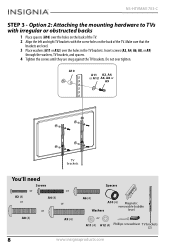
... A2, A4, or A12 A6, A8 or A9 TV brackets You'll need Screws or A2 (4) or A4 (4) or or or A8 (4) A9 (4) Spacers A6 (4) Washers A10 (4) Magnetic removable bubble level or A11 (4) A12 (4) Phillips screwdriver TV brackets (2) 8 www.insigniaproducts.com NS-HTVMM1703-C STEP 3 - Option 2: Attaching the mounting hardware to TVs with irregular or obstructed backs 1 Place...
... A2, A4, or A12 A6, A8 or A9 TV brackets You'll need Screws or A2 (4) or A4 (4) or or or A8 (4) A9 (4) Spacers A6 (4) Washers A10 (4) Magnetic removable bubble level or A11 (4) A12 (4) Phillips screwdriver TV brackets (2) 8 www.insigniaproducts.com NS-HTVMM1703-C STEP 3 - Option 2: Attaching the mounting hardware to TVs with irregular or obstructed backs 1 Place...

User Guide
Page 9
... center of your TV. lower than the center of the wall plate on top of the screen. Before you drill holes in . This is normally 40 to... player or cable box). Keep in . This is measurement a. 2 Measure the distance from the ground. The TV should be placed on the wall. Full Motion Mount for TVs 47" - 80" STEP 4 - from the floor to where you want...wall plate to be above any furniture (such as entertainment centers or TV stands). The total measurement is b. 3 Add a + b. This measurement is the height where you want the center of the TV should also be on the wall. 4 Use...
... center of your TV. lower than the center of the wall plate on top of the screen. Before you drill holes in . This is normally 40 to... player or cable box). Keep in . This is measurement a. 2 Measure the distance from the ground. The TV should be placed on the wall. Full Motion Mount for TVs 47" - 80" STEP 4 - from the floor to where you want...wall plate to be above any furniture (such as entertainment centers or TV stands). The total measurement is b. 3 Add a + b. This measurement is the height where you want the center of the TV should also be on the wall. 4 Use...
User Guide
Page 10
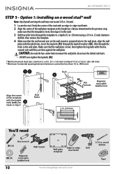
...in . NS-HTVMM1703-C STEP 5 - Stud finder 2 in. (50 mm) 3/16 (5 mm) You'll need Box wrench B1 (4) Wall mount B3 (4) Magnetic removable bubble level 3/16 in step 4. Make sure that the wall-mount arm on a wood stud* wall Note: Any drywall covering the wall must not exceed 5/8 in . (406 mm). CAUTION: Use only ...B3). * Minimum wood stud size: common 2 x 4 in. (51 x 102 mm) nominal 11/2 x 31/2 in. (38 x 89 mm). * Minimum horizontal spacing between fasteners cannot be less than 16 in . (16 mm). 1 Locate the stud. Option 1: Installing on the wall-mount is perpendicular to a depth of...
...in . NS-HTVMM1703-C STEP 5 - Stud finder 2 in. (50 mm) 3/16 (5 mm) You'll need Box wrench B1 (4) Wall mount B3 (4) Magnetic removable bubble level 3/16 in step 4. Make sure that the wall-mount arm on a wood stud* wall Note: Any drywall covering the wall must not exceed 5/8 in . (406 mm). CAUTION: Use only ...B3). * Minimum wood stud size: common 2 x 4 in. (51 x 102 mm) nominal 11/2 x 31/2 in. (38 x 89 mm). * Minimum horizontal spacing between fasteners cannot be less than 16 in . (16 mm). 1 Locate the stud. Option 1: Installing on the wall-mount is perpendicular to a depth of...

User Guide
Page 11
...anchors are firm against the wall plate. Mount the wall plate directly onto the concrete surface. 1 Align the center of 2.28 in. (58 mm) using a 3/8 in the wall plate. Make sure that the wall-mount arm on a solid concrete or concrete block wall CAUTION: To prevent property...drill bit, then remove the template. 3 Insert the concrete wall anchors (B2) into the mortar between fasteners cannot be less than 16 in . B2 B3 B1 Box Magnetic wrench removable bubble level You'll need B1 (6) B2 (6) Box wrench B3 (6) Wall mount Magnetic removable bubble level Wall plate template 3/8 in...
...anchors are firm against the wall plate. Mount the wall plate directly onto the concrete surface. 1 Align the center of 2.28 in. (58 mm) using a 3/8 in the wall plate. Make sure that the wall-mount arm on a solid concrete or concrete block wall CAUTION: To prevent property...drill bit, then remove the template. 3 Insert the concrete wall anchors (B2) into the mortar between fasteners cannot be less than 16 in . B2 B3 B1 Box Magnetic wrench removable bubble level You'll need B1 (6) B2 (6) Box wrench B3 (6) Wall mount Magnetic removable bubble level Wall plate template 3/8 in...
User Guide
Page 12
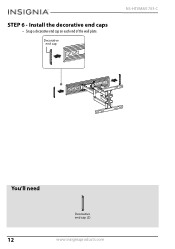
STEP 6 - Decorative end cap NS-HTVMM1703-C You'll need Decorative end cap (2) 12 www.insigniaproducts.com Install the decorative end caps • Snap a decorative end cap on each end of the wall plate.
STEP 6 - Decorative end cap NS-HTVMM1703-C You'll need Decorative end cap (2) 12 www.insigniaproducts.com Install the decorative end caps • Snap a decorative end cap on each end of the wall plate.
User Guide
Page 13
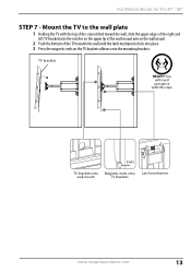
... top of the screen tilted toward the wall, slide the upper edges of the right and left TV brackets into the notches on the upper lip of the TV towards the wall until the latch mechanism clicks into Magnetic ends onto Latch mechanism wall-mount TV brackets www.insigniaproducts.com 13 Mount the TV to the wall plate 1 Holding...
... top of the screen tilted toward the wall, slide the upper edges of the right and left TV brackets into the notches on the upper lip of the TV towards the wall until the latch mechanism clicks into Magnetic ends onto Latch mechanism wall-mount TV brackets www.insigniaproducts.com 13 Mount the TV to the wall plate 1 Holding...
User Guide
Page 14
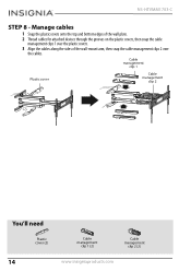
Cable management clip 1 Plastic cover Cable management clip 2 You'll need Plastic cover (2) 14 Cable management clip 1 (2) Cable management clip 2 (2) www.insigniaproducts.com Manage cables 1 Snap the plastic covers onto the top and bottom edges of the wall plate. 2 Thread cables for attached devices through the grooves on the plastic covers, then snap the cable management clips 1 over the plastic covers. 3 Align the cables along the sides of the wall-mount arm, then snap the cable management clips 2 over the cables. NS-HTVMM1703-C STEP 8 -
Cable management clip 1 Plastic cover Cable management clip 2 You'll need Plastic cover (2) 14 Cable management clip 1 (2) Cable management clip 2 (2) www.insigniaproducts.com Manage cables 1 Snap the plastic covers onto the top and bottom edges of the wall plate. 2 Thread cables for attached devices through the grooves on the plastic covers, then snap the cable management clips 1 over the plastic covers. 3 Align the cables along the sides of the wall-mount arm, then snap the cable management clips 2 over the cables. NS-HTVMM1703-C STEP 8 -
User Guide
Page 15
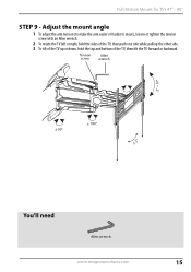
Tension screw Allen wrench -2° ~ 10° ± 90° ± 180° ± 3° You'll need Allen wrench www.insigniaproducts.com 15 Full Motion Mount for TVs 47" - 80" STEP 9 - Adjust the mount angle 1 To adjust the arm tension (to make the arm easier or harder to move), loosen or tighten the tension screw with an Allen wrench. 2 To rotate the TV left or right, hold the sides of the TV, then push one side while pulling the other side. 3 To tilt of the TV up or down, hold the top and bottom of the TV, then tilt the TV forward or backward.
Tension screw Allen wrench -2° ~ 10° ± 90° ± 180° ± 3° You'll need Allen wrench www.insigniaproducts.com 15 Full Motion Mount for TVs 47" - 80" STEP 9 - Adjust the mount angle 1 To adjust the arm tension (to make the arm easier or harder to move), loosen or tighten the tension screw with an Allen wrench. 2 To rotate the TV left or right, hold the sides of the TV, then push one side while pulling the other side. 3 To tilt of the TV up or down, hold the top and bottom of the TV, then tilt the TV forward or backward.
User Guide
Page 16
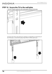
Secure the TV to unlock the brackets, then lift the TV off the wall mount. 16 www.insigniaproducts.com To remove the TV from the wall mount, pull down on both ribbons on the bottom of the TV brackets to the wall plate • Press the TV brackets against the wall-mounting plate until they lock into place. NS-HTVMM1703-C STEP 10 -
Secure the TV to unlock the brackets, then lift the TV off the wall mount. 16 www.insigniaproducts.com To remove the TV from the wall mount, pull down on both ribbons on the bottom of the TV brackets to the wall plate • Press the TV brackets against the wall-mounting plate until they lock into place. NS-HTVMM1703-C STEP 10 -
User Guide
Page 17
... put the Product in its sole option): (1) repair the Product with new or rebuilt parts; Where is determined to be defective by an authorized Insignia repair center or store personnel, Insignia will (at Best Buy branded retail stores or websites to the original purchaser of the Product ("Warranty Period"). Full Motion Mount for TVs 47" - 80" ONE-YEAR LIMITED...
... put the Product in its sole option): (1) repair the Product with new or rebuilt parts; Where is determined to be defective by an authorized Insignia repair center or store personnel, Insignia will (at Best Buy branded retail stores or websites to the original purchaser of the Product ("Warranty Period"). Full Motion Mount for TVs 47" - 80" ONE-YEAR LIMITED...
User Guide
Page 18
... a multiple dwelling condominium or apartment complex, or otherwise used in a place of other than a private home. • Modification of any part of the Product, including the antenna • Display panel damaged by Best Buy Purchasing, LLC 7601 Penn Ave South, Richfield, MN 55423 U.S.A. ©2016 Best Buy. REPAIR REPLACEMENT AS PROVIDED UNDER THIS WARRANTY IS YOUR EXCLUSIVE REMEDY...
... a multiple dwelling condominium or apartment complex, or otherwise used in a place of other than a private home. • Modification of any part of the Product, including the antenna • Display panel damaged by Best Buy Purchasing, LLC 7601 Penn Ave South, Richfield, MN 55423 U.S.A. ©2016 Best Buy. REPAIR REPLACEMENT AS PROVIDED UNDER THIS WARRANTY IS YOUR EXCLUSIVE REMEDY...

User Guide
Page 19
1-877-467-4289 www.insigniaproducts.com INSIGNIA is a trademark of Best Buy and its affiliated companies Distributed by Best Buy Purchasing, LLC 7601 Penn Ave South, Richfield, MN 55423 U.S.A. ©2016 Best Buy. All rights reserved Made in China V6 ENGLISH 16-0801
1-877-467-4289 www.insigniaproducts.com INSIGNIA is a trademark of Best Buy and its affiliated companies Distributed by Best Buy Purchasing, LLC 7601 Penn Ave South, Richfield, MN 55423 U.S.A. ©2016 Best Buy. All rights reserved Made in China V6 ENGLISH 16-0801

