Warranty Sheet
Page 1
... U.S.A. ©2019 Best Buy. The Warranty Period lasts for lengthy periods (burn-in its sole option): (1) repair the Product with this warranty statement. This warranty does not cover: • Customer instruction/education • Installation • Set up to liquids, gels or pastes. Where is " or "with new or rebuilt comparable products or parts. INSIGNIA PRODUCTS MAKES NO OTHER...
... U.S.A. ©2019 Best Buy. The Warranty Period lasts for lengthy periods (burn-in its sole option): (1) repair the Product with this warranty statement. This warranty does not cover: • Customer instruction/education • Installation • Set up to liquids, gels or pastes. Where is " or "with new or rebuilt comparable products or parts. INSIGNIA PRODUCTS MAKES NO OTHER...
User Guide
Page 1
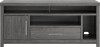
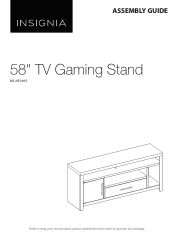
ASSEMBLY GUIDE 58" TV Gaming Stand NS-HF2007 Before using your new product, please read these instructions to prevent any damage.
ASSEMBLY GUIDE 58" TV Gaming Stand NS-HF2007 Before using your new product, please read these instructions to prevent any damage.

User Guide
Page 2
... tip over on audio and/or video equipment furniture. Contents IMPORTANT SAFEGUARDS 2 Features 3 Dimensions...3 Maximum weights 4 Package contents 5 Parts ...5 Hardware...6 Needed tool ...7 Assembly instructions 7 Maintaining your TV stand 50 Specifications 50 ONE-YEAR LIMITED WARRANTY 51 IMPORTANT SAFEGUARDS Please read and understand this entire manual before discarding packaging. • Use care when assembling your time and follow assembly instructions closely. Take your new product.
... tip over on audio and/or video equipment furniture. Contents IMPORTANT SAFEGUARDS 2 Features 3 Dimensions...3 Maximum weights 4 Package contents 5 Parts ...5 Hardware...6 Needed tool ...7 Assembly instructions 7 Maintaining your TV stand 50 Specifications 50 ONE-YEAR LIMITED WARRANTY 51 IMPORTANT SAFEGUARDS Please read and understand this entire manual before discarding packaging. • Use care when assembling your time and follow assembly instructions closely. Take your new product.
User Guide
Page 3
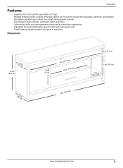
NS-HF2007 Features • Supports 65 in. (165 cm) TVs up to 60 lbs. (27.2 kg) • Multiple shelves provide a surplus of storage options for your game console, Blue-ray player, cable box, and speakers • Specially designated space allows for vertical-standing game ...consoles • Lower drawer stores remotes, controllers, cables, and more • Cabinet door hides your entertainment accessories for clutter-free organization • Adjustable horizontal shelf makes space for DVD and video ...
NS-HF2007 Features • Supports 65 in. (165 cm) TVs up to 60 lbs. (27.2 kg) • Multiple shelves provide a surplus of storage options for your game console, Blue-ray player, cable box, and speakers • Specially designated space allows for vertical-standing game ...consoles • Lower drawer stores remotes, controllers, cables, and more • Cabinet door hides your entertainment accessories for clutter-free organization • Adjustable horizontal shelf makes space for DVD and video ...

User Guide
Page 6
...assembly Cam screw CC DD Small cam lock Dowel EE 3 × 15 mm screw FF QTY. 12 1 set 42 40 44 6 LABEL MM NN OO PP QQ RR GG Magnetic door latch 1 SS 4 × 50 mm screw HH 6 TT 3 × 16 mm screw II 6 UU JJ Handle with screws... 2 VV KK Lower hinge pin 1 WW LL Upper hinge pin 1 58" TV Gaming Stand STAND PART Shelf support QTY. 4 3.5 × 12 mm screw 4 Drawer support 2 4 × 38 mm screw 6 4.5 × 14 mm screw 4 Back support bracket 12 3.5 × 16 mm screw 12 ...
...assembly Cam screw CC DD Small cam lock Dowel EE 3 × 15 mm screw FF QTY. 12 1 set 42 40 44 6 LABEL MM NN OO PP QQ RR GG Magnetic door latch 1 SS 4 × 50 mm screw HH 6 TT 3 × 16 mm screw II 6 UU JJ Handle with screws... 2 VV KK Lower hinge pin 1 WW LL Upper hinge pin 1 58" TV Gaming Stand STAND PART Shelf support QTY. 4 3.5 × 12 mm screw 4 Drawer support 2 4 × 38 mm screw 6 4.5 × 14 mm screw 4 Back support bracket 12 3.5 × 16 mm screw 12 ...

User Guide
Page 7
... 7 Needed tool NS-HF2007 Phillips screwdriver Assembly instructions STEP 1: You need: B Left divider panel (1) C Right divider panel (1) AA 3 × 12 mm screw (6) CL DL DR CR BB Left and right rail assembly (2) Phillips screwdriver 1 Separate the CL and CR parts of the rail assembly (BB) from the DL and DR parts and set the DL and DR parts aside for use in another step...
... 7 Needed tool NS-HF2007 Phillips screwdriver Assembly instructions STEP 1: You need: B Left divider panel (1) C Right divider panel (1) AA 3 × 12 mm screw (6) CL DL DR CR BB Left and right rail assembly (2) Phillips screwdriver 1 Separate the CL and CR parts of the rail assembly (BB) from the DL and DR parts and set the DL and DR parts aside for use in another step...

User Guide
Page 9
CC CC www.insigniaproducts.com 9 STEP 2: You need: CC Cam screw (4) Phillips screwdriver NS-HF2007 B Left divider C Right divider panel (1) panel (1) 1 Insert two cam screws (CC) into the holes on the left divider panel (B), then tighten the screws with a Phillips screwdriver. CC CC 2 Insert two cam screws (CC) into the holes on the right divider panel (C), then tighten the screws with a Phillips screwdriver.
CC CC www.insigniaproducts.com 9 STEP 2: You need: CC Cam screw (4) Phillips screwdriver NS-HF2007 B Left divider C Right divider panel (1) panel (1) 1 Insert two cam screws (CC) into the holes on the left divider panel (B), then tighten the screws with a Phillips screwdriver. CC CC 2 Insert two cam screws (CC) into the holes on the right divider panel (C), then tighten the screws with a Phillips screwdriver.

User Guide
Page 11
DD DD DD 2 Insert the cam screws on the divider panels (B and C) into the long lower shelf (D). STEP 4: You need: NS-HF2007 B Left divider C Right divider panel (1) panel (1) D Long lower shelf (1) DD Small cam lock (4) Phillips screwdriver Using cam locks When you insert a cam lock, position the open end of the lock toward the cam screw, then insert the cam screw into the cam lock opening. 1 Insert four cam locks (DD) into the cam locks on the long lower shelf, then tighten the locks with a Phillips screwdriver. www.insigniaproducts.com 11
DD DD DD 2 Insert the cam screws on the divider panels (B and C) into the long lower shelf (D). STEP 4: You need: NS-HF2007 B Left divider C Right divider panel (1) panel (1) D Long lower shelf (1) DD Small cam lock (4) Phillips screwdriver Using cam locks When you insert a cam lock, position the open end of the lock toward the cam screw, then insert the cam screw into the cam lock opening. 1 Insert four cam locks (DD) into the cam locks on the long lower shelf, then tighten the locks with a Phillips screwdriver. www.insigniaproducts.com 11
User Guide
Page 13
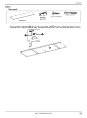
GG FF FF www.insigniaproducts.com 13 STEP 6: You need: NS-HF2007 E Upper shelf (1) GG Magnetic door latch (1) FF 3 × 15 mm screw (2) Phillips screwdriver • Align the magnetic door latch (GG) with the holes on the upper shelf (E), then secure the latch with two 3 × 15 mm screws (FF) using a Phillips screwdriver. Make sure that you attach the latch to the side of the shelf that has cross bars.
GG FF FF www.insigniaproducts.com 13 STEP 6: You need: NS-HF2007 E Upper shelf (1) GG Magnetic door latch (1) FF 3 × 15 mm screw (2) Phillips screwdriver • Align the magnetic door latch (GG) with the holes on the upper shelf (E), then secure the latch with two 3 × 15 mm screws (FF) using a Phillips screwdriver. Make sure that you attach the latch to the side of the shelf that has cross bars.

User Guide
Page 15
EE HH HH www.insigniaproducts.com 15 STEP 8: You need: E Upper shelf (1) NS-HF2007 EE Dowel (2) Y Small divider panel (1) HH 4 × 50 mm screw (2) Phillips screwdriver 1 Insert two dowels (EE) into the long edge of the small divider panel (Y). 2 Insert two 4 × 50 mm screws (HH) through the upper shelf (E) and into the small divider panel (Y), then tighten the screws with a Phillips screwdriver.
EE HH HH www.insigniaproducts.com 15 STEP 8: You need: E Upper shelf (1) NS-HF2007 EE Dowel (2) Y Small divider panel (1) HH 4 × 50 mm screw (2) Phillips screwdriver 1 Insert two dowels (EE) into the long edge of the small divider panel (Y). 2 Insert two 4 × 50 mm screws (HH) through the upper shelf (E) and into the small divider panel (Y), then tighten the screws with a Phillips screwdriver.

User Guide
Page 17
EE EE EE EE www.insigniaproducts.com 17 STEP 10: You need: EE Dowel (4) NS-HF2007 A Base (1) • Insert four dowels (EE) into the edge of the base (A). Make sure that you use the holes that don't have holes above them.
EE EE EE EE www.insigniaproducts.com 17 STEP 10: You need: EE Dowel (4) NS-HF2007 A Base (1) • Insert four dowels (EE) into the edge of the base (A). Make sure that you use the holes that don't have holes above them.

User Guide
Page 19
DD DD DD DD www.insigniaproducts.com 19 STEP 12: You need: NS-HF2007 A Base (1) F Front edge (1) DD Cam lock (4) Phillips screwdriver When you insert a cam lock, position the open end of the lock toward the cam screw, then insert the cam screw into the cam lock opening. 1 Insert four cam locks (DD) into the holes on the base (A). 2 Insert the cam screws and dowels on the front edge (F) into the cam locks and dowel holes on the base (A), then tighten the cam locks with a Phillips screwdriver.
DD DD DD DD www.insigniaproducts.com 19 STEP 12: You need: NS-HF2007 A Base (1) F Front edge (1) DD Cam lock (4) Phillips screwdriver When you insert a cam lock, position the open end of the lock toward the cam screw, then insert the cam screw into the cam lock opening. 1 Insert four cam locks (DD) into the holes on the base (A). 2 Insert the cam screws and dowels on the front edge (F) into the cam locks and dowel holes on the base (A), then tighten the cam locks with a Phillips screwdriver.
User Guide
Page 21
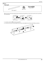
DD DD DD DD www.insigniaproducts.com 21 STEP 14: You need: H Lower support (1) DD Cam lock (4) Phillips screwdriver NS-HF2007 When you insert a cam lock, position the open end of the lock toward the cam screw, then insert the cam screw into the cam lock opening. 1 Insert four cam locks (DD) into lower support (H). 2 Insert the cam screws in the base (A) into the cam locks, then tighten the cam locks with a Phillips screwdriver.
DD DD DD DD www.insigniaproducts.com 21 STEP 14: You need: H Lower support (1) DD Cam lock (4) Phillips screwdriver NS-HF2007 When you insert a cam lock, position the open end of the lock toward the cam screw, then insert the cam screw into the cam lock opening. 1 Insert four cam locks (DD) into lower support (H). 2 Insert the cam screws in the base (A) into the cam locks, then tighten the cam locks with a Phillips screwdriver.

User Guide
Page 25
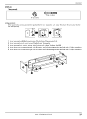
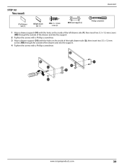
STEP 18: You need: NS-HF2007 DD Cam lock (6) Phillips screwdriver I Left side J Right side support (1) support (1) K left side (1) L Right side (1) When you insert a cam lock, position the open end of the lock toward the cam screw, then insert the cam screw into the cam lock opening. 1 Insert three cam locks ...left side (K) and three cam locks into the right side (L). 2 Insert the cam screws on the left support (I) and right support (J) into the cam locks on the left and right sides, then tighten the screws with a Phillips screwdriver. DD DD DD DD DD DD www.insigniaproducts.com 25
STEP 18: You need: NS-HF2007 DD Cam lock (6) Phillips screwdriver I Left side J Right side support (1) support (1) K left side (1) L Right side (1) When you insert a cam lock, position the open end of the lock toward the cam screw, then insert the cam screw into the cam lock opening. 1 Insert three cam locks ...left side (K) and three cam locks into the right side (L). 2 Insert the cam screws on the left support (I) and right support (J) into the cam locks on the left and right sides, then tighten the screws with a Phillips screwdriver. DD DD DD DD DD DD www.insigniaproducts.com 25
User Guide
Page 27
...20: You need: NS-HF2007 DD Cam lock (12) Phillips screwdriver Using cam locks When you insert a cam lock, position the open end of the lower shelf (H). 4 Insert the six cam screws on the right side (K) into the cam locks, then tighten the cam locks with a Phillips screwdriver. 5 Insert the six cam screws on the right...corner of the bottom of the upper shelf (E). 2 Insert one cam lock into each corner of the bottom of the base (A). 3 Insert two cam locks into the bottom of the left and right sides of the lock toward the cam screw, then insert the cam screw into the cam locks, then tighten ...
...20: You need: NS-HF2007 DD Cam lock (12) Phillips screwdriver Using cam locks When you insert a cam lock, position the open end of the lower shelf (H). 4 Insert the six cam screws on the right side (K) into the cam locks, then tighten the cam locks with a Phillips screwdriver. 5 Insert the six cam screws on the right...corner of the bottom of the upper shelf (E). 2 Insert one cam lock into each corner of the bottom of the base (A). 3 Insert two cam locks into the bottom of the left and right sides of the lock toward the cam screw, then insert the cam screw into the cam locks, then tighten ...

User Guide
Page 31
DD DD DD DD DD DD www.insigniaproducts.com 31 Make sure that the cam screws fit into the inside top edges of the left side (K), the right side (K), and the left top side of the lock toward the cam screw, then insert the cam screw into the cam lock opening. 1 Insert two cam locks (DD) into the cam locks, 3 Tighten all cam locks with a Phillips screwdriver. STEP 24: You need: NS-HF2007 DD Cam lock (6) Phillips screwdriver When you insert a cam lock, position the open end of the small divider (Y). 2 Lay the top (G) onto the left and right sides.
DD DD DD DD DD DD www.insigniaproducts.com 31 Make sure that the cam screws fit into the inside top edges of the left side (K), the right side (K), and the left top side of the lock toward the cam screw, then insert the cam screw into the cam lock opening. 1 Insert two cam locks (DD) into the cam locks, 3 Tighten all cam locks with a Phillips screwdriver. STEP 24: You need: NS-HF2007 DD Cam lock (6) Phillips screwdriver When you insert a cam lock, position the open end of the small divider (Y). 2 Lay the top (G) onto the left and right sides.
User Guide
Page 33
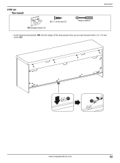
STEP 26: You need: NS-HF2007 SS 3.5 × 16 mm screw (12) RR Back support bracket (12) Phillips screwdriver • Insert twelve back brackets (RR) into the edges of the back panels, then secure each bracket with a 3.5 × 16 mm screw (SS). RR SS www.insigniaproducts.com 33
STEP 26: You need: NS-HF2007 SS 3.5 × 16 mm screw (12) RR Back support bracket (12) Phillips screwdriver • Insert twelve back brackets (RR) into the edges of the back panels, then secure each bracket with a 3.5 × 16 mm screw (SS). RR SS www.insigniaproducts.com 33
User Guide
Page 39
...NS-HF2007 P Left drawer side (1) Q Right drawer side (1) NN 3.5 × 12 mm screw (4) OO Drawer support (2) Phillips screwdriver 1 Align a drawer support (OO) with the holes on the inside of the left drawer side (P), then insert two 3.5 × 12 mm screws (NN) through the outside of the drawer and into the support. 2 Tighten the screws... with a Phillips screwdriver. 3 Align a drawer support (OO) with the holes on the inside of the right drawer ...
...NS-HF2007 P Left drawer side (1) Q Right drawer side (1) NN 3.5 × 12 mm screw (4) OO Drawer support (2) Phillips screwdriver 1 Align a drawer support (OO) with the holes on the inside of the left drawer side (P), then insert two 3.5 × 12 mm screws (NN) through the outside of the drawer and into the support. 2 Tighten the screws... with a Phillips screwdriver. 3 Align a drawer support (OO) with the holes on the inside of the right drawer ...

User Guide
Page 50
Temperature and humidity changes can cause chemical changes that may damage the furniture. We recommend that you keep your stand away from direct sunlight because sun may cause damage to use polish, test first in . (147.3 x 64.5 × 39.4 cm) 100.3 lbs (45.5 kg) ... when dusting. • Use of your furniture as it may damage the finish. Specifications Dimensions (WxHxD) Weight 58 x 25.4 x 15.5 in an inconspicuous area. • Using solvents of wood. Use a soft, clean, cloth and blot the spill gently. Should you to clean your TV stand. Heat can cause fading,...
Temperature and humidity changes can cause chemical changes that may damage the furniture. We recommend that you keep your stand away from direct sunlight because sun may cause damage to use polish, test first in . (147.3 x 64.5 × 39.4 cm) 100.3 lbs (45.5 kg) ... when dusting. • Use of your furniture as it may damage the finish. Specifications Dimensions (WxHxD) Weight 58 x 25.4 x 15.5 in an inconspicuous area. • Using solvents of wood. Use a soft, clean, cloth and blot the spill gently. Should you to clean your TV stand. Heat can cause fading,...

User Guide
Page 51
... not returned to you. If service of Products or parts are required after the Warranty Period expires, you must be purchased in the United States or Canada from the date of your Insignia Product during the Warranty Period. This warranty does not cover: • Customer instruction/education • Installation • Set up adjustments • Cosmetic damage • Damage...
... not returned to you. If service of Products or parts are required after the Warranty Period expires, you must be purchased in the United States or Canada from the date of your Insignia Product during the Warranty Period. This warranty does not cover: • Customer instruction/education • Installation • Set up adjustments • Cosmetic damage • Damage...

