
Service Guide
Page 25
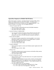
... the Central Electronics Complex (CEC) chips when the POWER Button is pressed. Service Processor in the system and performs a simple test on an ASCII terminal connected to start the Stand-alone Diagnostics (CD or Tape). - The CPU compatibility test is E1XX - LCD Code range is run. "5" or "F5" to execute and... Test The system firmware tests the system memory and identifies failing memory cards and memory module locations. LCD Code range is E0A0 - "6" or "F6" to serial port 1. 3.
... the Central Electronics Complex (CEC) chips when the POWER Button is pressed. Service Processor in the system and performs a simple test on an ASCII terminal connected to start the Stand-alone Diagnostics (CD or Tape). - The CPU compatibility test is E1XX - LCD Code range is run. "5" or "F5" to execute and... Test The system firmware tests the system memory and identifies failing memory cards and memory module locations. LCD Code range is E0A0 - "6" or "F6" to serial port 1. 3.
Service Guide
Page 47
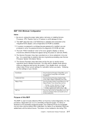
... normal diagnostics. The failure is identified. From the System Power Control Menu go to the failing FRU. For this MAP This MAP is installed and connected to 0 (zero) 2. Chapter 2. From the Call-In/Call-Out Setup Menu, go to examine that a CD-ROM drive is used to... locate defective FRUs not found by the user to monitor server operations and to the Serial Port Selection Menu and disable call-out on both serial ports. Maintenance Analysis Procedures 2-17 The Service Processor may wish to No. It is detected on a minimally-configured...
... normal diagnostics. The failure is identified. From the System Power Control Menu go to the failing FRU. For this MAP This MAP is installed and connected to 0 (zero) 2. Chapter 2. From the Call-In/Call-Out Setup Menu, go to examine that a CD-ROM drive is used to... locate defective FRUs not found by the user to monitor server operations and to the Serial Port Selection Menu and disable call-out on both serial ports. Maintenance Analysis Procedures 2-17 The Service Processor may wish to No. It is detected on a minimally-configured...

Service Guide
Page 54
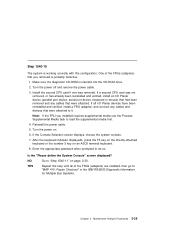
Also connect the internal serial and Ethernet cables to do so. 7. If an ASCII terminal has been defined as the system console, install the display adapter and connect the display to it. This triggers the SMS. 6. Turn the power off. 2. b. Plug the keyboard into the keyboard ... Guide Enter the appropriate password when prompted to the I/O planar. If the ASCII terminal or graphics display (including display adapter) are connected differently than before, the Console Selection screen appears and requires that a new console be selected. 5. Wait until the SMS screen is...
Also connect the internal serial and Ethernet cables to do so. 7. If an ASCII terminal has been defined as the system console, install the display adapter and connect the display to it. This triggers the SMS. 6. Turn the power off. 2. b. Plug the keyboard into the keyboard ... Guide Enter the appropriate password when prompted to the I/O planar. If the ASCII terminal or graphics display (including display adapter) are connected differently than before, the Console Selection screen appears and requires that a new console be selected. 5. Wait until the SMS screen is...
Service Guide
Page 59
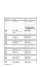
...Planar devices have been reinstalled and verified, install a FRU (adapter) and connect any cables that you installed requires supplemental media use the Process Supplemental Media task to "MAP 410: ...Repair Checkout" in the IBM RS/6000 Diagnostic Information for Multiple Bus Systems. Chapter 2. YES Repeat this configuration.... system is working correctly with this step until all I /O Planar device (parallel port device, serial port device, keyboard or mouse) that had been removed and any cables and devices that were attached...
...Planar devices have been reinstalled and verified, install a FRU (adapter) and connect any cables that you installed requires supplemental media use the Process Supplemental Media task to "MAP 410: ...Repair Checkout" in the IBM RS/6000 Diagnostic Information for Multiple Bus Systems. Chapter 2. YES Repeat this configuration.... system is working correctly with this step until all I /O Planar device (parallel port device, serial port device, keyboard or mouse) that had been removed and any cables and devices that were attached...
Service Guide
Page 108
... the note on 3-29. Probe for 512KB. Have network administrator verify the server configuration for general considerations. 1. See the note on 3-29. Create serial node. Verify the network connection (network could be down). 3. See the note on 3-29. Create Service Processor node. Create tablet node. Create op-panel node. 3-36 Service Guide...
... the note on 3-29. Probe for 512KB. Have network administrator verify the server configuration for general considerations. 1. See the note on 3-29. Create serial node. Verify the network connection (network could be down). 3. See the note on 3-29. Create Service Processor node. Create tablet node. Create op-panel node. 3-36 Service Guide...
Service Guide
Page 118
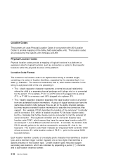
...are produced by the standard dash (-) or slash (/) character. In contrast, the location code P2-K1 actually points to the device connected to the actual SCSI bus and devices. Location Codes This system unit uses Physical Location Codes in the string is a physical child... identifier in conjunction with AIX Location Codes to describe the connectors they support. Location Code Format The format for logical functions, such as serial port 1, but a different external connector. The - (dash) separator character represents a normal structural relationship where the child is an alphanumeric...
...are produced by the standard dash (-) or slash (/) character. In contrast, the location code P2-K1 actually points to the device connected to the actual SCSI bus and devices. Location Codes This system unit uses Physical Location Codes in the string is a physical child... identifier in conjunction with AIX Location Codes to describe the connectors they support. Location Code Format The format for logical functions, such as serial port 1, but a different external connector. The - (dash) separator character represents a normal structural relationship where the child is an alphanumeric...
Service Guide
Page 122
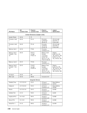
... 16 Memory Card 2 Memory Card 2 moduleS 1 thru 16 I/O board FMC card Diskette Drive Keyboard Mouse Diskette Port Keyboard Port Mouse Port Serial Port 1 AIX Location Code Physical Location Code Physical Connection 00-00 00-00 00-00 00-00 00-00 00-00 00-00 00-00 00-00 Central Electronics Complex...
... 16 Memory Card 2 Memory Card 2 moduleS 1 thru 16 I/O board FMC card Diskette Drive Keyboard Mouse Diskette Port Keyboard Port Mouse Port Serial Port 1 AIX Location Code Physical Location Code Physical Connection 00-00 00-00 00-00 00-00 00-00 00-00 00-00 00-00 00-00 Central Electronics Complex...
Service Guide
Page 123
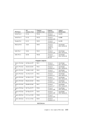
FRU Name Serial Port 2 Serial Port 3 Parallel Port Ethernet Port SCSI Port 1 SCSI Port 2 Card in PCI Slot 1P Card in PCI Slot 2P Card in PCI Slot 3P Card ...-S3 01-R1 10-80 10-60 30-58 Physical Location Code P2/S2 P2/S3 P2/R1 P2/E1 P2/Z1 P2/Z2 Physical Connection I/O board Connector J41 I/O board Connector J50 I/O board Connector J47 I/O board Connector J18(TH) or J21(TP) I/O board Connector J25 I /O board Connector J91 SCSI Devices Logical...
FRU Name Serial Port 2 Serial Port 3 Parallel Port Ethernet Port SCSI Port 1 SCSI Port 2 Card in PCI Slot 1P Card in PCI Slot 2P Card in PCI Slot 3P Card ...-S3 01-R1 10-80 10-60 30-58 Physical Location Code P2/S2 P2/S3 P2/R1 P2/E1 P2/Z1 P2/Z2 Physical Connection I/O board Connector J41 I/O board Connector J50 I/O board Connector J47 I/O board Connector J18(TH) or J21(TP) I/O board Connector J25 I /O board Connector J91 SCSI Devices Logical...

Service Guide
Page 133
.... Pdisks, Hdisks, and Disk Drive Module Identification The physical disk drives (pdisks) in slot 1 of the 6-pack. The SSA loop must be connected next to the internal pair of one or more physical disk drives. A maximum of three dummy disk drive modules can be found by the machine...-readable serial number that occur on the front of the SSA link. The configuration software also allocates an identification (hdisk and pdisk number) to each other...
.... Pdisks, Hdisks, and Disk Drive Module Identification The physical disk drives (pdisks) in slot 1 of the 6-pack. The SSA loop must be connected next to the internal pair of one or more physical disk drives. A maximum of three dummy disk drive modules can be found by the machine...-readable serial number that occur on the front of the SSA link. The configuration software also allocates an identification (hdisk and pdisk number) to each other...

Service Guide
Page 157
...; │ ssa1 - 5 SSA ADAPTER │ │ │ │ To set or reset Identify, move cursor onto selection, then press Enter. │ │ │ │ Physical Serial# Adapter Port │ │ │ │ A1 A2 B1 B2 Status │ │ {TOP} │ │ pdisk nnnnnnnn 7 Good │ │ pdisk1 nnnnnnnn 1 6 Good │...; │ │ │ F3=Cancel F1 =Exit │ │ │ Note: Scroll the display to FRU Index 3-85 Chapter 3. Error Code to see all the connected disk drive modules.
...; │ ssa1 - 5 SSA ADAPTER │ │ │ │ To set or reset Identify, move cursor onto selection, then press Enter. │ │ │ │ Physical Serial# Adapter Port │ │ │ │ A1 A2 B1 B2 Status │ │ {TOP} │ │ pdisk nnnnnnnn 7 Good │ │ pdisk1 nnnnnnnn 1 6 Good │...; │ │ │ F3=Cancel F1 =Exit │ │ │ Note: Scroll the display to FRU Index 3-85 Chapter 3. Error Code to see all the connected disk drive modules.

Service Guide
Page 159
...│ ssa1 - 5 SSA ADAPTER │ │ │ │ To set or reset Identify, move cursor onto selection, then press Enter. │ │ │ │ Physical Serial# Adapter Port │ │ │ │ A1 A2 B1 B2 Status │ │ {TOP} │ │ pdisk nnnnnnnn Good │ │ pdisk1 nnnnnnnn 1 Good &#...2 Good │ │ {MORE} │ │ │ │ F3=Cancel F1 =Exit │ │ │ Note that the column for adapter connector A2 shows no connections. Error Code to FRU Index 3-87 Chapter 3.
...│ ssa1 - 5 SSA ADAPTER │ │ │ │ To set or reset Identify, move cursor onto selection, then press Enter. │ │ │ │ Physical Serial# Adapter Port │ │ │ │ A1 A2 B1 B2 Status │ │ {TOP} │ │ pdisk nnnnnnnn Good │ │ pdisk1 nnnnnnnn 1 Good &#...2 Good │ │ {MORE} │ │ │ │ F3=Cancel F1 =Exit │ │ │ Note that the column for adapter connector A2 shows no connections. Error Code to FRU Index 3-87 Chapter 3.

Service Guide
Page 254
Remove the cables from the rear of the system. 4. Connect the cables as follows: P1 P2 P3 J41 (I/O planar) J47 (I/O planar) J50 (I /O planar connectors J41, J47, and J50. 5. Remove the I/O planar cover as described in reverse order. Remove the external serial and parallel connectors from the I /O planar) 6-46 Service Guide Replacement Replace in "Covers" on page 6-8. 3. Remove the screws that attach the serial/parallel card to the system. If you have not already done so, remove the covers as described on page 6-3. 2. Serial/Parallel Card Removal 1.
Remove the cables from the rear of the system. 4. Connect the cables as follows: P1 P2 P3 J41 (I/O planar) J47 (I/O planar) J50 (I /O planar connectors J41, J47, and J50. 5. Remove the I/O planar cover as described in reverse order. Remove the external serial and parallel connectors from the I /O planar) 6-46 Service Guide Replacement Replace in "Covers" on page 6-8. 3. Remove the screws that attach the serial/parallel card to the system. If you have not already done so, remove the covers as described on page 6-3. 2. Serial/Parallel Card Removal 1.

Service Guide
Page 281
...you for a password (if set ), and when verified, displays the Service Processor menus. Menus may be confirmed by connecting an ASCII terminal to the appropriate serial port and turn the modem on the ASCII terminal to confirm its presence. Privileged user menus - Because the presence of..., how to drain capacitance while power is powered down, the Service Processor menus may be accessed locally or remotely. Connect the modem to either serial port. How to access Service Processor menus remotely Service Processor menus may be accessed remotely by pressing any key on ...
...you for a password (if set ), and when verified, displays the Service Processor menus. Menus may be confirmed by connecting an ASCII terminal to the appropriate serial port and turn the modem on the ASCII terminal to confirm its presence. Privileged user menus - Because the presence of..., how to drain capacitance while power is powered down, the Service Processor menus may be accessed locally or remotely. Connect the modem to either serial port. How to access Service Processor menus remotely Service Processor menus may be accessed remotely by pressing any key on ...
Service Guide
Page 296
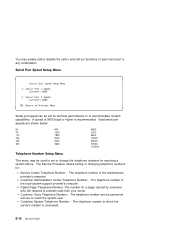
... the maintenance provider's computer. Customer Voice Telephone Number: - A speed of each serial port in and call-out functions of 9600 baud or higher is connected. Customer Administration Center Telephone Number: - Valid serial port speeds are shown below: 50 600 4800 75 1200 7200 110 1800 9600... the call-in any combination. The telephone number of the local system support provider's computer. B-18 Service Guide Serial Port Speed Setup Menu Serial Port Speed Setup Menu 1. You may be set or change the telephone numbers for terminal performance or to accommodate modem...
... the maintenance provider's computer. Customer Voice Telephone Number: - A speed of each serial port in and call-out functions of 9600 baud or higher is connected. Customer Administration Center Telephone Number: - Valid serial port speeds are shown below: 50 600 4800 75 1200 7200 110 1800 9600... the call-in any combination. The telephone number of the local system support provider's computer. B-18 Service Guide Serial Port Speed Setup Menu Serial Port Speed Setup Menu 1. You may be set or change the telephone numbers for terminal performance or to accommodate modem...

Service Guide
Page 304
...battery operated, so power interruptions occurring while the server is restored. Ring Indicate Power-On Enabling ring indicate power-on your server can only be connected to the shutdown -t command on when AC loss occurred, it remains off do not affect its accuracy. Refer to "Seamless Transfer of AIX...taken. If a remote terminal is to be used, the modem must be assured when Unattended Power-On Mode is already on Switch - refer to serial port 1, and the operating system set the timer so that your server powers on - see Enable/Disable Unattended Power-On Mode in your clock ...
...battery operated, so power interruptions occurring while the server is restored. Ring Indicate Power-On Enabling ring indicate power-on your server can only be connected to the shutdown -t command on when AC loss occurred, it remains off do not affect its accuracy. Refer to "Seamless Transfer of AIX...taken. If a remote terminal is to be used, the modem must be assured when Unattended Power-On Mode is already on Switch - refer to serial port 1, and the operating system set the timer so that your server powers on - see Enable/Disable Unattended Power-On Mode in your clock ...

Service Guide
Page 309
...Processor to retry, continuing to place pager calls for the paging function. Note: Some modems, such as IBM 7857-017, are not designed for the number of the following : Have a modem connected to serial port 1 or 2. Restarts To enable the call out policy, etc). Appendix B. Call Out (Call-...Home) The Service Processor can be used for the serial port where the modem is connected. - Set up the following using the Service Processor Menus or Diagnostic Service Aids: - phone numbers for call out, call out feature...
...Processor to retry, continuing to place pager calls for the paging function. Note: Some modems, such as IBM 7857-017, are not designed for the number of the following : Have a modem connected to serial port 1 or 2. Restarts To enable the call out policy, etc). Appendix B. Call Out (Call-...Home) The Service Processor can be used for the serial port where the modem is connected. - Set up the following using the Service Processor Menus or Diagnostic Service Aids: - phone numbers for call out, call out feature...

Service Guide
Page 310
... modem. c. Note: A quick disconnect is already in progress. System Configuration: Service Processor Modem connected to one serial port and enabled for incoming calls Local ASCII terminal connected to enable console mirroring. Local session is accomplished by hitting the key sequence Ctrl+D on a... local ASCII terminal to monitor the Service Processor activities of the serial ports to the system firmware. Console Mirroring...
... modem. c. Note: A quick disconnect is already in progress. System Configuration: Service Processor Modem connected to one serial port and enabled for incoming calls Local ASCII terminal connected to enable console mirroring. Local session is accomplished by hitting the key sequence Ctrl+D on a... local ASCII terminal to monitor the Service Processor activities of the serial ports to the system firmware. Console Mirroring...

Service Guide
Page 324
... has been initialized recently. In case recovery becomes necessary, your system is difficult to DTR. Usually the command &D2 will hold a connection while DTR is enabled, and drop the connection when DTR is the mechanism by which the server "hangs up properly to respond to access physically, is set up " on... sets the modem response to assure it with remote users, it is communicating, and to the Data Terminal Ready (DTR) signal from the server's serial port. This is released. Recovery 2. It may be shut down as gracefully as there are two methods for the &Dn command.
... has been initialized recently. In case recovery becomes necessary, your system is difficult to DTR. Usually the command &D2 will hold a connection while DTR is enabled, and drop the connection when DTR is the mechanism by which the server "hangs up properly to respond to access physically, is set up " on... sets the modem response to assure it with remote users, it is communicating, and to the Data Terminal Ready (DTR) signal from the server's serial port. This is released. Recovery 2. It may be shut down as gracefully as there are two methods for the &Dn command.
Service Guide
Page 325
...configuration files2. 2. After the operating system is the correct response. See your server's modem. To set up . This then breaks the connection. The modem is the correct response. Appendix D. Will the server's modem disconnect when the power drops? Recovery Strategy The recovery strategy ... modem. If no , try another &Dn setting for your model manual for this .) Watch for configuring your server's serial ports. With the remote terminal connected to serial port 1 and defined as the primary console device, there are using modem_z.cfg or modem_z0.cfg, you cannot control DTR...
...configuration files2. 2. After the operating system is the correct response. See your server's modem. To set up . This then breaks the connection. The modem is the correct response. Appendix D. Will the server's modem disconnect when the power drops? Recovery Strategy The recovery strategy ... modem. If no , try another &Dn setting for your model manual for this .) Watch for configuring your server's serial ports. With the remote terminal connected to serial port 1 and defined as the primary console device, there are using modem_z.cfg or modem_z0.cfg, you cannot control DTR...

Service Guide
Page 326
... you choose to use the unused serial port as the primary console to manifest the modem's response to be affected. As a result, that serial device's connection and function could be a permanent part of your server, you the desired seamless connection at your remote terminal. D-8 Service... Guide Your remote terminal will be sent to any serial device attached to that port. These impacts may...
... you choose to use the unused serial port as the primary console to manifest the modem's response to be affected. As a result, that serial device's connection and function could be a permanent part of your server, you the desired seamless connection at your remote terminal. D-8 Service... Guide Your remote terminal will be sent to any serial device attached to that port. These impacts may...


