
Service Guide
Page 4
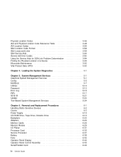
... 5-7 Utilities 5-10 Password 5-12 Error Log 5-16 RIPL 5-17 SCSI ID 5-21 Update 5-22 Text-Based System Management Services 5-24 Chapter 6. Removal and Replacement Procedures 6-1 Handling Static-Sensitive Devices 6-2 Covers 6-3 Power Supply 6-15 CD-ROM Drive, Tape Drive, Diskette Drive 6-19 Backplane 6-20 Adapters 6-22 Memory Cards 6-26 Memory Module 6-29 I/O Planar...
... 5-7 Utilities 5-10 Password 5-12 Error Log 5-16 RIPL 5-17 SCSI ID 5-21 Update 5-22 Text-Based System Management Services 5-24 Chapter 6. Removal and Replacement Procedures 6-1 Handling Static-Sensitive Devices 6-2 Covers 6-3 Power Supply 6-15 CD-ROM Drive, Tape Drive, Diskette Drive 6-19 Backplane 6-20 Adapters 6-22 Memory Cards 6-26 Memory Module 6-29 I/O Planar...

Service Guide
Page 29
...the equipment that has its own power cables: a. Note: The correction of any other contamination within the system unit. 9. Check the covers for sharp edges and for damage or alterations that it is inspected for 0.1 ohm or less resistance between the ground lug on the external..., and any unsafe condition is the responsibility of the owner of the system unit. 2. Check the external power cable for damage to Off. 5. Remove the covers. 6. Check for damage. 11. Service Inspection Guide Perform a service inspection on the system when: The system is steady. 4. Changes have those ...
...the equipment that has its own power cables: a. Note: The correction of any other contamination within the system unit. 9. Check the covers for sharp edges and for damage or alterations that it is inspected for 0.1 ohm or less resistance between the ground lug on the external..., and any unsafe condition is the responsibility of the owner of the system unit. 2. Check the external power cable for damage to Off. 5. Remove the covers. 6. Check for damage. 11. Service Inspection Guide Perform a service inspection on the system when: The system is steady. 4. Changes have those ...

Service Guide
Page 49
...configuration. YES Go to assure stability, depending on page 2-21. Remove all external cables. 5. Record the position of the memory DIMMs. Remove all installed memory DIMMs except for the operator panel to the adapters. Remove the second Memory card, if present. 10. Chapter 2. Exit ...20. NO Go to each other. Plug in J1 and J2, not J1 and J3. 9. Remove the side cover 6. Remove the second processor card (if present). [If second processor removed, ensure first CPU cable is installed.] 8. Disconnect the diskette drive cable from the diskette drive connector...
...configuration. YES Go to assure stability, depending on page 2-21. Remove all external cables. 5. Record the position of the memory DIMMs. Remove all installed memory DIMMs except for the operator panel to the adapters. Remove the second Memory card, if present. 10. Chapter 2. Exit ...20. NO Go to each other. Plug in J1 and J2, not J1 and J3. 9. Remove the side cover 6. Remove the second processor card (if present). [If second processor removed, ensure first CPU cable is installed.] 8. Disconnect the diskette drive cable from the diskette drive connector...

Service Guide
Page 114
... DIMM pair could be installed in module slots 5 and 6 (slots 3 and 4 do not, however, replace the covers as suspect bad and Power the system up . c. Refer to the "Removal and Replacement Procedures" for "Memory Modules" on page 6-26 for there to be 2 partially populated Memory Cards, the first... one be installed before memory on module removal and installation (do not have to be populated first). a. If there is usable. Move the suspect bad tag from the installed Memory Card...
... DIMM pair could be installed in module slots 5 and 6 (slots 3 and 4 do not, however, replace the covers as suspect bad and Power the system up . c. Refer to the "Removal and Replacement Procedures" for "Memory Modules" on page 6-26 for there to be 2 partially populated Memory Cards, the first... one be installed before memory on module removal and installation (do not have to be populated first). a. If there is usable. Move the suspect bad tag from the installed Memory Card...

Service Guide
Page 211
Covers Removal 1. Open the door. Removal and Replacement Procedures 6-3 Chapter 6.
Covers Removal 1. Open the door. Removal and Replacement Procedures 6-3 Chapter 6.

Service Guide
Page 214
b. Unlock the keylock on the left side of the front cover. 6-6 Service Guide Lift up on the latch on the front cover. 8. Remove the front cover: a.
b. Unlock the keylock on the left side of the front cover. 6-6 Service Guide Lift up on the latch on the front cover. 8. Remove the front cover: a.

Service Guide
Page 215
Detach the front cover's bottom hooks from the grooves located on the bottom of the system, and lift the front cover off the bottom of the system and pull it forward. (The front cover is held in place by two spring detented ball studs.) d. Chapter 6. Removal and Replacement Procedures 6-7 Grasp the sides of the front cover near the top of the system. c.
Detach the front cover's bottom hooks from the grooves located on the bottom of the system, and lift the front cover off the bottom of the system and pull it forward. (The front cover is held in place by two spring detented ball studs.) d. Chapter 6. Removal and Replacement Procedures 6-7 Grasp the sides of the front cover near the top of the system. c.

Service Guide
Page 216
Remove the cover by carefully lifting it in a safe place. 10. b. Store it up and off the hinges. Remove the I/O Planar cover: Attention If your system has the SSA bulkhead cable installed, make sure that you do not damage the cable as you remove the I /O planar cover and unlatch the cover. 6-8 Service Guide a. 9. Open the side cover to a 90 degree angle. Loosen the three screws (2 turns) on the I /O planar cover. Remove the side cover: a.
Remove the cover by carefully lifting it in a safe place. 10. b. Store it up and off the hinges. Remove the I/O Planar cover: Attention If your system has the SSA bulkhead cable installed, make sure that you do not damage the cable as you remove the I /O planar cover and unlatch the cover. 6-8 Service Guide a. 9. Open the side cover to a 90 degree angle. Loosen the three screws (2 turns) on the I /O planar cover. Remove the side cover: a.

Service Guide
Page 217
Removal and Replacement Procedures 6-9 Chapter 6. b. Remove the I/O planar cover.
Removal and Replacement Procedures 6-9 Chapter 6. b. Remove the I/O planar cover.

Service Guide
Page 219
Push the side cover to close it. Reinstall the side cover: a. b. 2. Slide the side cover down. Place the side cover at a 90 degree angle. Chapter 6. Align the pins on the rear of the side cover with the two hinges on the rear of the system. Removal and Replacement Procedures 6-11 c.
Push the side cover to close it. Reinstall the side cover: a. b. 2. Slide the side cover down. Place the side cover at a 90 degree angle. Chapter 6. Align the pins on the rear of the side cover with the two hinges on the rear of the system. Removal and Replacement Procedures 6-11 c.

Service Guide
Page 221
Removal and Replacement Procedures 6-13 Latch the cover latch located on the left side of the system by aligning the pins with the hinges, and sliding the door down. Reinstall the door at the front of the front cover. 4. e. Chapter 6.
Removal and Replacement Procedures 6-13 Latch the cover latch located on the left side of the system by aligning the pins with the hinges, and sliding the door down. Reinstall the door at the front of the front cover. 4. e. Chapter 6.

Service Guide
Page 223
Power supplies are not serviceable and are to open the covers of the power supply. Disconnect the four cables from I/O Planar connectors P1, and P2. 3. Removal and Replacement Procedures 6-15 Disconnect the two cables from the System Card connectors J1, J2 J3, and J4. 4. Chapter 6. Removal 1. Disconnect the cables from the Processor Cards. If you have not already done so, remove the covers as a unit. Power Supply DANGER Do not attempt to be replaced as described in "Covers" on page 6-3. 2.
Power supplies are not serviceable and are to open the covers of the power supply. Disconnect the four cables from I/O Planar connectors P1, and P2. 3. Removal and Replacement Procedures 6-15 Disconnect the two cables from the System Card connectors J1, J2 J3, and J4. 4. Chapter 6. Removal 1. Disconnect the cables from the Processor Cards. If you have not already done so, remove the covers as a unit. Power Supply DANGER Do not attempt to be replaced as described in "Covers" on page 6-3. 2.

Service Guide
Page 227
Disconnect the power and signal cables to remove. If you are inside. Chapter 6. Slide the drive forward to the drive you have not already done so, remove the covers as described in reverse order. Replacement Replace in "Covers" on page 6-3. 2. Removal 1. Removal and Replacement Procedures 6-19 no user adjustments or serviceable parts are removing. 3. CD-ROM Drive, Tape Drive, Diskette Drive CAUTION: Do not open the drive;
Disconnect the power and signal cables to remove. If you are inside. Chapter 6. Slide the drive forward to the drive you have not already done so, remove the covers as described in reverse order. Replacement Replace in "Covers" on page 6-3. 2. Removal 1. Removal and Replacement Procedures 6-19 no user adjustments or serviceable parts are removing. 3. CD-ROM Drive, Tape Drive, Diskette Drive CAUTION: Do not open the drive;

Service Guide
Page 228
Slide the backplane out to gain cable access. 4. If you have not already done so, remove the covers as described in "Covers" on page 6-3. 2. Disconnect the SCSI cable, EPOW cable, and power supply cable from the backplane. 3. Backplane Removal 1. Remove the backplane. 6-20 Service Guide Remove the screw from the backplane. 5.
Slide the backplane out to gain cable access. 4. If you have not already done so, remove the covers as described in "Covers" on page 6-3. 2. Disconnect the SCSI cable, EPOW cable, and power supply cable from the backplane. 3. Backplane Removal 1. Remove the backplane. 6-20 Service Guide Remove the screw from the backplane. 5.

Service Guide
Page 230
If you want to remove. 6-22 Service Guide Locate the adapter connectors and determine which adapter you have not already done so, remove the covers as described in "Covers" on page 6-8. 3. Remove the I/O planar cover as described in on page 6-3. 2. Adapters Removal 1.
If you want to remove. 6-22 Service Guide Locate the adapter connectors and determine which adapter you have not already done so, remove the covers as described in "Covers" on page 6-8. 3. Remove the I/O planar cover as described in on page 6-3. 2. Adapters Removal 1.

Service Guide
Page 233
Replace any parts previously removed in "Covers" on page 6-3. Chapter 6. Replace the covers as described in reverse order. 5. Install the new adapter. 4. Removal and Replacement Procedures 6-25 3.
Replace any parts previously removed in "Covers" on page 6-3. Chapter 6. Replace the covers as described in reverse order. 5. Install the new adapter. 4. Removal and Replacement Procedures 6-25 3.

Service Guide
Page 234
Remove the memory adapter card shield. 4. Attention: To prevent damage to determine your next step. 3. then return here to the card and the card connectors, open and close the retainer hooks at the same time. 6-26 Service Guide The card is secured in "Covers" on page 6-3. 2. Open the card retainer hooks and remove the card. Memory Cards Removal 1. Remove the I/O planar cover as described in place with card retainer hooks, one on page 6-8; If you have not already done so, remove the covers as described on each end of the card.
Remove the memory adapter card shield. 4. Attention: To prevent damage to determine your next step. 3. then return here to the card and the card connectors, open and close the retainer hooks at the same time. 6-26 Service Guide The card is secured in "Covers" on page 6-3. 2. Open the card retainer hooks and remove the card. Memory Cards Removal 1. Remove the I/O planar cover as described in place with card retainer hooks, one on page 6-8; If you have not already done so, remove the covers as described on each end of the card.

Service Guide
Page 235
... the black tabs on the new card are installing the card in the card guide rails. 5. Align the card with the connector. 7. Removal and Replacement Procedures 6-27 Remove the connector cover if you are captured by the retainer hooks. 6. Replacement 1. Attention: To prevent damage to the card and the card connectors, open and...
... the black tabs on the new card are installing the card in the card guide rails. 5. Align the card with the connector. 7. Removal and Replacement Procedures 6-27 Remove the connector cover if you are captured by the retainer hooks. 6. Replacement 1. Attention: To prevent damage to the card and the card connectors, open and...

Service Guide
Page 236
Replace the covers as described in reverse order. 10. Install the memory shield on page 6-3. 6-28 Service Guide 8. Replace any parts previously removed in "Covers" on the bottom memory card. . 9.
Replace the covers as described in reverse order. 10. Install the memory shield on page 6-3. 6-28 Service Guide 8. Replace any parts previously removed in "Covers" on the bottom memory card. . 9.

Service Guide
Page 237
Removal and Replacement Procedures 6-29 Memory Module Removal 1. Remove the memory card as described in "Covers" on page 6-26. 4. Locate the memory module connectors and determine which module you have not already done so, remove the covers as described on page 6-8. 3. Chapter 6. If you want to remove. Remove the I/O planar cover as described in "Memory Cards" on page 6-3. 2.
Removal and Replacement Procedures 6-29 Memory Module Removal 1. Remove the memory card as described in "Covers" on page 6-26. 4. Locate the memory module connectors and determine which module you have not already done so, remove the covers as described on page 6-8. 3. Chapter 6. If you want to remove. Remove the I/O planar cover as described in "Memory Cards" on page 6-3. 2.


