
Service Guide
Page 4
... 6-3 Power Supply 6-15 CD-ROM Drive, Tape Drive, Diskette Drive 6-19 Backplane 6-20 Adapters 6-22 Memory Cards 6-26 Memory Module 6-29 I/O Planar 6-31 Processor Card 6-35 Service Processor 6-37 Battery 6-38 Fans 6-42 Operator Panel Display 6-44 Operator Panel Control Assembly 6-45 Serial/Parallel Card 6-46 iv Service Guide Physical Location Codes...
... 6-3 Power Supply 6-15 CD-ROM Drive, Tape Drive, Diskette Drive 6-19 Backplane 6-20 Adapters 6-22 Memory Cards 6-26 Memory Module 6-29 I/O Planar 6-31 Processor Card 6-35 Service Processor 6-37 Battery 6-38 Fans 6-42 Operator Panel Display 6-44 Operator Panel Control Assembly 6-45 Serial/Parallel Card 6-46 iv Service Guide Physical Location Codes...

Service Guide
Page 5
... Cables 7-7 Appendix A. Modem Configurations D-1 Sample Modem Configuration Files D-1 Configuration File Selection D-2 Seamless Transfer of a Modem Session D-6 Modem Configuration Samples D-9 Appendix E. Service Processor Operational Phases E-1 Index X-1 Reader's Comments - Service Processor Menus Service Processor Menus General User Menus Privileged User Menus Service Processor Functions and Features B-1 B-3 B-4 B-6 B-24 Appendix C. We'd Like to Hear From You X-3 Preface v Service...
... Cables 7-7 Appendix A. Modem Configurations D-1 Sample Modem Configuration Files D-1 Configuration File Selection D-2 Seamless Transfer of a Modem Session D-6 Modem Configuration Samples D-9 Appendix E. Service Processor Operational Phases E-1 Index X-1 Reader's Comments - Service Processor Menus Service Processor Menus General User Menus Privileged User Menus Service Processor Functions and Features B-1 B-3 B-4 B-6 B-24 Appendix C. We'd Like to Hear From You X-3 Preface v Service...
Service Guide
Page 25
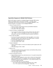
...is E000 - "5" or "F5" to start the On-line Diagnostics (Hard Disk) Chapter 1. LCD Code range is checked. Service Processor Self Test Service Processor card performs self test and NVRAM initialization. E07F. The VPD data is read and the CRC is E0A0 - Memory Test The system ...the LCD display by hitting the "1" key (if ASCII terminal) or the "F1" key (if Graphics terminal). Built-In-Self-Test (BIST) The Service Processor initiates Built-In-Self-Test (BIST) on , the System Support Controller (SSC) startup begins, and releases reset to serial port 1. 3. Reference Information 1-9...
...is E000 - "5" or "F5" to start the On-line Diagnostics (Hard Disk) Chapter 1. LCD Code range is checked. Service Processor Self Test Service Processor card performs self test and NVRAM initialization. E07F. The VPD data is read and the CRC is E0A0 - Memory Test The system ...the LCD display by hitting the "1" key (if ASCII terminal) or the "F1" key (if Graphics terminal). Built-In-Self-Test (BIST) The Service Processor initiates Built-In-Self-Test (BIST) on , the System Support Controller (SSC) startup begins, and releases reset to serial port 1. 3. Reference Information 1-9...

Service Guide
Page 32
...are displayed on the system console, the system pauses and then restarts. ASCII terminal, the boot indicator ( ) is ready. You have STBY displayed The Service Processor (SP) is displayed on a graphics terminal. 2-2 Service Guide Go to isolate the problem. Use MAP 1540 to "E1xx Code Boot Problems" on page ...3-44. Go to the Fast Path MAP in the IBM RS/6000 Diagnostic Information for Multiple Bus Systems. The system POST indicators are displayed on the system console. This condition can be requested by ...
...are displayed on the system console, the system pauses and then restarts. ASCII terminal, the boot indicator ( ) is ready. You have STBY displayed The Service Processor (SP) is displayed on a graphics terminal. 2-2 Service Guide Go to isolate the problem. Use MAP 1540 to "E1xx Code Boot Problems" on page ...3-44. Go to the Fast Path MAP in the IBM RS/6000 Diagnostic Information for Multiple Bus Systems. The system POST indicators are displayed on the system console. This condition can be requested by ...
Service Guide
Page 36
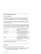
...to monitor server operations and to attempt recoveries. Following are asked to perform certain actions based on both serial ports. From the Service Processor System Power Control Menu, disable unattended start mode. From the System Power Control Menu, go to the Surveillance Setup Menu and disable...policy to "Step 1020-1." From the Call-In/Call-Out Setup Menu, go to MAP 0020 in the IBM RS/6000 Diagnostic Information for restoration before proceeding (see Service Processor System Information Menu). Step 1020-1 The following steps analyze a failure to load the diagnostic programs. Note: ...
...to monitor server operations and to attempt recoveries. Following are asked to perform certain actions based on both serial ports. From the Service Processor System Power Control Menu, disable unattended start mode. From the System Power Control Menu, go to the Surveillance Setup Menu and disable...policy to "Step 1020-1." From the Call-In/Call-Out Setup Menu, go to MAP 0020 in the IBM RS/6000 Diagnostic Information for restoration before proceeding (see Service Processor System Information Menu). Step 1020-1 The following steps analyze a failure to load the diagnostic programs. Note: ...

Service Guide
Page 44
... Repeat this step until the defective FRU is defective. Power supply I /O planar, service processor, or the system card is identified or all the FRUs have been exchanged, go to "MAP 410: Repair Checkout..." in the IBM RS/6000 Diagnostic Information for Multiple Bus Systems. 2-14 Service Guide YES Go to "Step ...wall outlet. 5. Step 1520-3 Note: Either the cooling fans, the power supply, the I /O planar Service Processor System card Front cooling fans (one of the FRUs in the list. 4. Does the fan in the following...
... Repeat this step until the defective FRU is defective. Power supply I /O planar, service processor, or the system card is identified or all the FRUs have been exchanged, go to "MAP 410: Repair Checkout..." in the IBM RS/6000 Diagnostic Information for Multiple Bus Systems. 2-14 Service Guide YES Go to "Step ...wall outlet. 5. Step 1520-3 Note: Either the cooling fans, the power supply, the I /O planar Service Processor System card Front cooling fans (one of the FRUs in the list. 4. Does the fan in the following...
Service Guide
Page 47
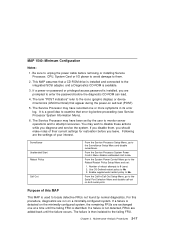
...planar to avoid damage to the failing FRU. Surveillance Unattended Start Reboot Policy Call Out From the Service Processor Setup Menu, go to 0 (zero) 2. From the Service Processor System Power Control Menu disable unattended start mode. If a failure is not detected, FRUs are added ...power-on a minimally-configured system. MAP 1540: Minimum Configuration Notes: 1. Be sure to unplug the power cable before proceeding (see Service Processor System Information Menu). 6. Following are run on self-test (POST). 5. The term "POST indicators" refer to disable these actions while ...
...planar to avoid damage to the failing FRU. Surveillance Unattended Start Reboot Policy Call Out From the Service Processor Setup Menu, go to 0 (zero) 2. From the Service Processor System Power Control Menu disable unattended start mode. If a failure is not detected, FRUs are added ...power-on a minimally-configured system. MAP 1540: Minimum Configuration Notes: 1. Be sure to unplug the power cable before proceeding (see Service Processor System Information Menu). 6. Following are run on self-test (POST). 5. The term "POST indicators" refer to disable these actions while ...

Service Guide
Page 49
... Plug in slots that are stable as soon as they appear. Step 1540-2 1. If you have not already done so, configure the Service Processor with code E1F2, E1F3, E1F7, or STBY? Disconnect the internal serial and parallel cables. 13. Does the operator panel stabilize with the instructions... (and wait for OK on page 2-17 and then return here and continue. 3. Disconnect all the adapters. 7. Remove the second processor card (if present). [If second processor removed, ensure first CPU cable is installed.] 8. Remove the second Memory card, if present. 10. NO Go to the adapters. ...
... Plug in slots that are stable as soon as they appear. Step 1540-2 1. If you have not already done so, configure the Service Processor with code E1F2, E1F3, E1F7, or STBY? Disconnect the internal serial and parallel cables. 13. Does the operator panel stabilize with the instructions... (and wait for OK on page 2-17 and then return here and continue. 3. Disconnect all the adapters. 7. Remove the second processor card (if present). [If second processor removed, ensure first CPU cable is installed.] 8. Remove the second Memory card, if present. 10. NO Go to the adapters. ...

Service Guide
Page 50
...the symptom did not change and all the FRUs have been exchanged, call for a I /O planar (see notes on page 2-18 in the IBM RS/6000 Diagnostic Information for the operator panel to assure stability, depending on page 2-1.) 5. System Card 6. Does the operator panel stabilize with code ...E1F2, E1F3, E1F7, or STBY? I /O planar to "Step 1540-1" on page 2-1. Service Processor Wait for Multiple Bus Systems. 2-20 Service Guide Repeat the FRU replacement steps until the defective FRU is defective. Other checkpoints may take up to...
...the symptom did not change and all the FRUs have been exchanged, call for a I /O planar (see notes on page 2-18 in the IBM RS/6000 Diagnostic Information for the operator panel to assure stability, depending on page 2-1.) 5. System Card 6. Does the operator panel stabilize with code ...E1F2, E1F3, E1F7, or STBY? I /O planar to "Step 1540-1" on page 2-1. Service Processor Wait for Multiple Bus Systems. 2-20 Service Guide Repeat the FRU replacement steps until the defective FRU is defective. Other checkpoints may take up to...

Service Guide
Page 57
... to "Step 1540-1" on page 2-18 in the system unit is defined as a graphical display. 4. Last SCSI device connected (CD-ROM drive, tape drive, etc.) 3. Processor card 6. NO One of the FRUs remaining in this step until all the FRUs have not been exchanged: 1. Repeat this MAP and follow the instructions...
... to "Step 1540-1" on page 2-18 in the system unit is defined as a graphical display. 4. Last SCSI device connected (CD-ROM drive, tape drive, etc.) 3. Processor card 6. NO One of the FRUs remaining in this step until all the FRUs have not been exchanged: 1. Repeat this MAP and follow the instructions...

Service Guide
Page 76
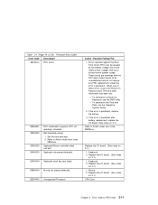
... FRU If for password entry. Replace I /O board. (See notes on 3-1.) 3. Example: 000.000.000.000 Enter valid (numeric) IP parameter in keyboard. 2. Replace the Service Processor. 2. Turn off , turn on system unit. 2. Turn off , turn on system unit. 2. replace the I /O board. (See notes on system unit. 2. Replace I /O board. (See notes... for jumper location and position. 1. Replace I /O board should always have (at least) 2 integrated PCI SCSI controllers; Table 3-1 (Page 3 of 0 to communicate with the Service processor. Firmware Error Codes. Enter valid IP parameter.
... FRU If for password entry. Replace I /O board. (See notes on 3-1.) 3. Example: 000.000.000.000 Enter valid (numeric) IP parameter in keyboard. 2. Replace the Service Processor. 2. Turn off , turn on system unit. 2. Turn off , turn on system unit. 2. replace the I /O board. (See notes on system unit. 2. Replace I /O board. (See notes... for jumper location and position. 1. Replace I /O board should always have (at least) 2 integrated PCI SCSI controllers; Table 3-1 (Page 3 of 0 to communicate with the Service processor. Firmware Error Codes. Enter valid IP parameter.
Service Guide
Page 83
... notes on 3-1.) 1. Chapter 3. Set the time and date. 2. Keyboard not present/detected. 29A00004 Keyboard stuck key test failed. 29B00004 Mouse not present/detected. 2B200402 Unsupported Processor. Errors reported against the Real Time Clock (RTC) can be re-established and do not require any FRU replacement unless the error is persistent. Mouse...
... notes on 3-1.) 1. Chapter 3. Set the time and date. 2. Keyboard not present/detected. 29A00004 Keyboard stuck key test failed. 29B00004 Mouse not present/detected. 2B200402 Unsupported Processor. Errors reported against the Real Time Clock (RTC) can be re-established and do not require any FRU replacement unless the error is persistent. Mouse...

Service Guide
Page 84
...power indicator remains off and the operator panel is blank. 2. Replace the I/O board. (See notes on 3-1.) 3-12 Service Guide Replace the service processor card. 4. If problem persists, replace battery. 2. Replace the I /O board. (See notes on 3-1.) 1. Plug the system power cable back... in and retry the operation. 3. See error code 2B2xxx22 for xxx definitions. Replace the service processor card. 4. Unplug the system power cable and wait until the system power indicator remains off and the operator panel is blank. 2. ...
...power indicator remains off and the operator panel is blank. 2. Replace the I/O board. (See notes on 3-1.) 3-12 Service Guide Replace the service processor card. 4. If problem persists, replace battery. 2. Replace the I /O board. (See notes on 3-1.) 1. Plug the system power cable back... in and retry the operation. 3. See error code 2B2xxx22 for xxx definitions. Replace the service processor card. 4. Unplug the system power cable and wait until the system power indicator remains off and the operator panel is blank. 2. ...

Service Guide
Page 85
...VPD module from the old operator panel control assembly to the new one . Use the System Firmware diskette to re-program the service processor firmware. 2. Replace the system board. Firmware Error Codes. Replace the battery. 2. Replace the operator panel control assembly. (See notes... the old operator panel control assembly to FRU Index 3-13 Error Code Description 2BA00014 Service processor reports bad service processor firmware. 2BA00017 Service processor reports bad or low battery. 2BA00018 EPOW test failure. 2BA00019 IRQ13 test failure. 2BA00024 2BA00040 Service...
...VPD module from the old operator panel control assembly to the new one . Use the System Firmware diskette to re-program the service processor firmware. 2. Replace the system board. Firmware Error Codes. Replace the battery. 2. Replace the operator panel control assembly. (See notes... the old operator panel control assembly to FRU Index 3-13 Error Code Description 2BA00014 Service processor reports bad service processor firmware. 2BA00017 Service processor reports bad or low battery. 2BA00018 EPOW test failure. 2BA00019 IRQ13 test failure. 2BA00024 2BA00040 Service...

Service Guide
Page 86
... 2BA00073 VPD data corrupted for CPU in slot 1. 2BA00100 Service processor firmware recovery information could not be written to diskette. 2BA00101 Service processor is the same level as the service processor firmware, update cancelled. Check diskette media write protect tab. 2. ... 1. 1. Retry operation. Install the service processor. 2. See error code 2BA00200 for recovery procedure. If problem persists, replace service processor. See error code 2BA00200 for recovery procedure. 3-14 Service Guide Service processor firmware update error occurred, update not completed....
... 2BA00073 VPD data corrupted for CPU in slot 1. 2BA00100 Service processor firmware recovery information could not be written to diskette. 2BA00101 Service processor is the same level as the service processor firmware, update cancelled. Check diskette media write protect tab. 2. ... 1. 1. Retry operation. Install the service processor. 2. See error code 2BA00200 for recovery procedure. If problem persists, replace service processor. See error code 2BA00200 for recovery procedure. 3-14 Service Guide Service processor firmware update error occurred, update not completed....

Service Guide
Page 87
... cool air flow obstructions to the system. 2. Replace Memory Card. Error Code to the system. 2. Error Code Description 2BA00203 Service processor firmware update error occurred, update not completed. Replace Fan 1. 2. If problem persists, replace Power Supply. 3. Replace I /O Board...on 3-1.) 1. If the problem persists, replace CPU Card 1. Error occurred while reading new service processor CRC after updating service processor firmware. 2BA00204 Service processor firmware update error occurred, update not completed. See error code 2BA00200 for cool air flow obstructions to...
... cool air flow obstructions to the system. 2. Replace Memory Card. Error Code to the system. 2. Error Code Description 2BA00203 Service processor firmware update error occurred, update not completed. Replace Fan 1. 2. If problem persists, replace Power Supply. 3. Replace I /O Board...on 3-1.) 1. If the problem persists, replace CPU Card 1. Error occurred while reading new service processor CRC after updating service processor firmware. 2BA00204 Service processor firmware update error occurred, update not completed. See error code 2BA00200 for cool air flow obstructions to...

Service Guide
Page 88
Error Code Description 2BA00313 Service Processor reports Generic Power Alert. 2BA00314 Service Processor reports 5V Over Voltage Alert. 2BA00315 Service Processor reports 5V Under Voltage Alert. 2BA00316 Service Processor reports 3.3V Over Voltage Alert. 2BA00317 Service Processor reports 3.3V Under Voltage Alert. 2BA00318 Service Processor reports 2.5V Over Voltage Alert. 2BA00319 Service Processor reports 2.5V Under Voltage Alert...
Error Code Description 2BA00313 Service Processor reports Generic Power Alert. 2BA00314 Service Processor reports 5V Over Voltage Alert. 2BA00315 Service Processor reports 5V Under Voltage Alert. 2BA00316 Service Processor reports 3.3V Over Voltage Alert. 2BA00317 Service Processor reports 3.3V Under Voltage Alert. 2BA00318 Service Processor reports 2.5V Over Voltage Alert. 2BA00319 Service Processor reports 2.5V Under Voltage Alert...

Service Guide
Page 89
..., replace I /O Board. (See notes on 3-1.) 1. Error Code Description 2BA00327 Service Processor reports PCI Expansion Card 5V Under Voltage Alert. 2BA00328 Service Processor reports PCI Expansion Card 3.3V Over Voltage Alert. 2BA00329 Service Processor reports PCI Expansion Card 3.3V Under Voltage Alert. 2BA00330 Service Processor reports PCI Expansion Card +12V Over Voltage Alert. 2BA00331 Service...
..., replace I /O Board. (See notes on 3-1.) 1. Error Code Description 2BA00327 Service Processor reports PCI Expansion Card 5V Under Voltage Alert. 2BA00328 Service Processor reports PCI Expansion Card 3.3V Over Voltage Alert. 2BA00329 Service Processor reports PCI Expansion Card 3.3V Under Voltage Alert. 2BA00330 Service Processor reports PCI Expansion Card +12V Over Voltage Alert. 2BA00331 Service...

Service Guide
Page 90
.... 2. Table 3-1 (Page 17 of AC power (power button). Error Code Description 2BA00337 Service Processor reports Memory Critical Over Temperature Slow Shutdown request. 2BA00338 Service Processor reports Generic Fast Shutdown request. 2BA00340 Service Processor reports Locked fan Fast Shutdown request fan number 1. 2BA00341 Service Processor reports Locked fan Fast Shutdown request fan number 2. 2BA00342 Service...
.... 2. Table 3-1 (Page 17 of AC power (power button). Error Code Description 2BA00337 Service Processor reports Memory Critical Over Temperature Slow Shutdown request. 2BA00338 Service Processor reports Generic Fast Shutdown request. 2BA00340 Service Processor reports Locked fan Fast Shutdown request fan number 1. 2BA00341 Service Processor reports Locked fan Fast Shutdown request fan number 2. 2BA00342 Service...
Service Guide
Page 91
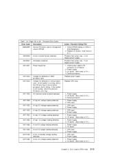
...A loss of 24). If the system is not running , refer to the AIX error log to find out which processor card is running , refer to the Service Processor error log.) An unknown power problem detected. 40111022 A high 5.0 voltage reading detected. 40111032 A high 3.3 voltage reading...detected on I/O Board. 2. Firmware Error Codes. Replace I/O Board. (See notes on 3-1.) 3. Error Code to P2 connector on either processor card. Service processor. 1. CPU card. 2. If not, replace power supply. I /O board 1. Power supply. 1. Power supply. 3. Voltage not detected on 3-1.) Chapter...
...A loss of 24). If the system is not running , refer to the AIX error log to find out which processor card is running , refer to the Service Processor error log.) An unknown power problem detected. 40111022 A high 5.0 voltage reading detected. 40111032 A high 3.3 voltage reading...detected on I/O Board. 2. Firmware Error Codes. Replace I/O Board. (See notes on 3-1.) 3. Error Code to P2 connector on either processor card. Service processor. 1. CPU card. 2. If not, replace power supply. I /O board 1. Power supply. 1. Power supply. 3. Voltage not detected on 3-1.) Chapter...


