
Service Guide
Page 4
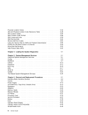
Removal and Replacement Procedures 6-1 Handling Static-Sensitive Devices 6-2 Covers 6-3 Power Supply 6-15 CD-ROM Drive, Tape Drive, Diskette Drive 6-19 Backplane 6-20 Adapters 6-22 Memory Cards 6-26 Memory Module 6-29 I/O Planar 6-31 Processor Card 6-35 Service Processor 6-37 Battery 6-38 Fans 6-42 Operator Panel Display 6-44 Operator Panel Control Assembly 6-45 Serial/Parallel...
Removal and Replacement Procedures 6-1 Handling Static-Sensitive Devices 6-2 Covers 6-3 Power Supply 6-15 CD-ROM Drive, Tape Drive, Diskette Drive 6-19 Backplane 6-20 Adapters 6-22 Memory Cards 6-26 Memory Module 6-29 I/O Planar 6-31 Processor Card 6-35 Service Processor 6-37 Battery 6-38 Fans 6-42 Operator Panel Display 6-44 Operator Panel Control Assembly 6-45 Serial/Parallel...
Service Guide
Page 25
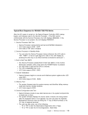
... Diagnostics (CD or Tape). - System Initialization System firmware begins to execute and initializes system registers after LCD code E0E1. Memory Test The system firmware tests the system memory and identifies failing memory cards and memory module locations. Device Configuration and Test System firmware checks to see what devices are in Standby Mode You can...
... Diagnostics (CD or Tape). - System Initialization System firmware begins to execute and initializes system registers after LCD code E0E1. Memory Test The system firmware tests the system memory and identifies failing memory cards and memory module locations. Device Configuration and Test System firmware checks to see what devices are in Standby Mode You can...
Service Guide
Page 38
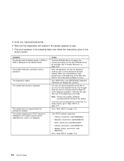
... Step. Note: Perform the systems shutdown procedure before turning off the system. If you are sure you pressed the correct key in the IBM RS/6000 Diagnostic Information for Multiple Bus Systems. You may not have pressed the correct key or you were to indicate a Service Mode...you have pressed the key soon enough when you may not have entered a valid password go to enter a password. If the POST indicator represents: memory, record error code M0MEM002. The system login prompt is entered. SCSI, record error code M0CON000. speaker (audio), record error code M0BT0000. Enter any...
... Step. Note: Perform the systems shutdown procedure before turning off the system. If you are sure you pressed the correct key in the IBM RS/6000 Diagnostic Information for Multiple Bus Systems. You may not have pressed the correct key or you were to indicate a Service Mode...you have pressed the key soon enough when you may not have entered a valid password go to enter a password. If the POST indicator represents: memory, record error code M0MEM002. The system login prompt is entered. SCSI, record error code M0CON000. speaker (audio), record error code M0BT0000. Enter any...

Service Guide
Page 45
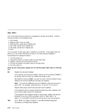
..." in the power supply turn on and the power LED come on and stay on . Chapter 2. Unplug the system unit power cable from all installed memory cards. 5. Remove all the SCSI devices. 7. Turn the power off. 2. Label and record the location of all the fans, except the fan in the power... of any cables attached to "Step 1520-5" on page 2-16. NO Replace the I/O planar. Remove all the adapters. 4. Step 1520-4 1. Does the fan in the IBM RS/6000 Diagnostic Information for Multiple Bus Systems. YES Go to the adapters. Go to the wall outlet. 9.
..." in the power supply turn on and the power LED come on and stay on . Chapter 2. Unplug the system unit power cable from all installed memory cards. 5. Remove all the SCSI devices. 7. Turn the power off. 2. Label and record the location of all the fans, except the fan in the power... of any cables attached to "Step 1520-5" on page 2-16. NO Replace the I/O planar. Remove all the adapters. 4. Step 1520-4 1. Does the fan in the IBM RS/6000 Diagnostic Information for Multiple Bus Systems. YES Go to the adapters. Go to the wall outlet. 9.
Service Guide
Page 46
... 2. PCI cards, lowest slot to "MAP 410: Repair Checkout" in the IBM RS/6000 Diagnostic Information for the new symptom. Fans. Install or connect one pair... the fan in this MAP and follow the instructions for Multiple Bus Systems. 2-16 Service Guide If the memory card was just installed, remove all the parts have been replaced, call your service support person for loose...1. Turn the power on , the most recently installed or connected part is causing the problem. Re-install the memory DIMMs, one of the parts in slots that are next to highest bay. 4. ISA cards, lowest slot to ...
... 2. PCI cards, lowest slot to "MAP 410: Repair Checkout" in the IBM RS/6000 Diagnostic Information for the new symptom. Fans. Install or connect one pair... the fan in this MAP and follow the instructions for Multiple Bus Systems. 2-16 Service Guide If the memory card was just installed, remove all the parts have been replaced, call your service support person for loose...1. Turn the power on , the most recently installed or connected part is causing the problem. Re-install the memory DIMMs, one of the parts in slots that are next to highest bay. 4. ISA cards, lowest slot to ...

Service Guide
Page 49
... take up to 3 minutes to "Step 1540-3" on . 15. Maintenance Analysis Procedures 2-19 Label and record the location of the memory DIMMs. Remove all installed memory DIMMs except for one pair from the SCSI connectors on page 2-17 and then return here and continue. 3. Wait for OK on ... stabilize with the instructions on step 6 on the I /O planar. 12. Chapter 2. Remove the second Memory card, if present. 10. Disconnect the SCSI cable from the first Memory card. Note: The memory DIMM pair must be installed in slots that are stable as soon as they appear. Step 1540-2 1. ...
... take up to 3 minutes to "Step 1540-3" on . 15. Maintenance Analysis Procedures 2-19 Label and record the location of the memory DIMMs. Remove all installed memory DIMMs except for one pair from the SCSI connectors on page 2-17 and then return here and continue. 3. Wait for OK on ... stabilize with the instructions on step 6 on the I /O planar. 12. Chapter 2. Remove the second Memory card, if present. 10. Disconnect the SCSI cable from the first Memory card. Note: The memory DIMM pair must be installed in slots that are stable as soon as they appear. Step 1540-2 1. ...

Service Guide
Page 50
...5. NO Reinstall the original FRU. Repeat the FRU replacement steps until the defective FRU is defective. Memory DIMMs (pair) 3. Step 1540-3 One of the FRUs remaining in the IBM RS/6000 Diagnostic Information for Multiple Bus Systems. 2-20 Service Guide If the following FRUs in this ...MAP and follow the instructions for the new symptom. Memory card 4. I /O planar to assure stability, depending on page 2-1....
...5. NO Reinstall the original FRU. Repeat the FRU replacement steps until the defective FRU is defective. Memory DIMMs (pair) 3. Step 1540-3 One of the FRUs remaining in the IBM RS/6000 Diagnostic Information for Multiple Bus Systems. 2-20 Service Guide If the following FRUs in this ...MAP and follow the instructions for the new symptom. Memory card 4. I /O planar to assure stability, depending on page 2-1....

Service Guide
Page 51
... the power cable. 4. Does the operator panel stabilize with the second memory card (if previously installed). NO Go to "Step 1540-7" on page 2-22. YES Repeat this configuration. 1. Install a pair of the memory DIMMs from the second memory card except 1 pair. Note: Checkpoints E1F2, E1F3 and STBY are ...installed and tested, record the positions of the memory DIMMs in the second memory card. Repeat this step with code E1F2, E1F3, E1F7, or STBY? Chapter 2. Wait for the operator panel to assure stability, depending on ...
... the power cable. 4. Does the operator panel stabilize with the second memory card (if previously installed). NO Go to "Step 1540-7" on page 2-22. YES Repeat this configuration. 1. Install a pair of the memory DIMMs from the second memory card except 1 pair. Note: Checkpoints E1F2, E1F3 and STBY are ...installed and tested, record the positions of the memory DIMMs in the second memory card. Repeat this step with code E1F2, E1F3, E1F7, or STBY? Chapter 2. Wait for the operator panel to assure stability, depending on ...

Service Guide
Page 52
Exchange the last memory DIMM pair installed. 3. Turn the power on system configuration. Wait for the operator panel to "MAP 410: Repair Checkout" in the IBM RS/6000 Diagnostic Information for Multiple Bus Systems. 2-22 Service Guide Reinstall the power cable. 4. Note: Checkpoints E1F2, E1F3 and ... at a checkpoint. Turn the power off and remove the power cable. 2. Other checkpoints may be caused by the last pair of memory DIMMs installed or the memory card. NO Go to assure stability, depending on . 5. To isolate the failing FRU, do the following: 1. Does the operator ...
Exchange the last memory DIMM pair installed. 3. Turn the power on system configuration. Wait for the operator panel to "MAP 410: Repair Checkout" in the IBM RS/6000 Diagnostic Information for Multiple Bus Systems. 2-22 Service Guide Reinstall the power cable. 4. Note: Checkpoints E1F2, E1F3 and ... at a checkpoint. Turn the power off and remove the power cable. 2. Other checkpoints may be caused by the last pair of memory DIMMs installed or the memory card. NO Go to assure stability, depending on . 5. To isolate the failing FRU, do the following: 1. Does the operator ...

Service Guide
Page 53
...and STBY are stable as soon as they appear. Repeat this MAP, and follow the instructions for the operator panel to stabilize at a checkpoint. Memory card b. Reinstall the power cable. 4. If the symptom has changed, check for loose cards, cables, and obvious problems. If you do ...FRU is defective. 1. Maintenance Analysis Procedures 2-23 Other checkpoints may take up to 3 minutes to "MAP 410: Repair Checkout" in the IBM RS/6000 Diagnostic Information for assistance. Exchange the following FRUs the order listed. Does the operator panel stabilize with code E1F2, E1F3, E1F7...
...and STBY are stable as soon as they appear. Repeat this MAP, and follow the instructions for the operator panel to stabilize at a checkpoint. Memory card b. Reinstall the power cable. 4. If the symptom has changed, check for loose cards, cables, and obvious problems. If you do ...FRU is defective. 1. Maintenance Analysis Procedures 2-23 Other checkpoints may take up to 3 minutes to "MAP 410: Repair Checkout" in the IBM RS/6000 Diagnostic Information for assistance. Exchange the following FRUs the order listed. Does the operator panel stabilize with code E1F2, E1F3, E1F7...

Service Guide
Page 78
... Ready Failed - DevOfl cmd. 21E00xxx SCSI Tape 21ED0xxx SCSI Changer. 21EE0xxx Other SCSI device type. 21F00xxx SCSI CD-ROM. 21F20xxx SCSI Read/Write Optical. 25000000 Memory Controller Failed. 3-6 Service Guide Action / Possible Failing FRU Notes: 1. Ensure that the controller and each device on the SCSI bus is properly terminated. b. c. Refer to...
... Ready Failed - DevOfl cmd. 21E00xxx SCSI Tape 21ED0xxx SCSI Changer. 21EE0xxx Other SCSI device type. 21F00xxx SCSI CD-ROM. 21F20xxx SCSI Read/Write Optical. 25000000 Memory Controller Failed. 3-6 Service Guide Action / Possible Failing FRU Notes: 1. Ensure that the controller and each device on the SCSI bus is properly terminated. b. c. Refer to...

Service Guide
Page 81
...problem resolution: 1. Retry the operation. 3. Refer to Action under error code 25AA0xxx. Refer to Action under error code 25AA0xxx. See "Memory PD Bits" on page 3-26 for definition of 24). Firmware Error Codes. Error Code Description 25A80210 Setenv/$Setenv parameter error - value contains... error. 25AA0005 Write-disable error. 25AA0006 Write-Trans error. 25AA0007 Unable to lock EEPROM. 25B00001 No memory modules detected in either memory card 1 or 2. 25Cyyxxx Memory Card problems. Action / Possible Failing FRU Refer to Action under error code 25A80xxx. Refer to Action ...
...problem resolution: 1. Retry the operation. 3. Refer to Action under error code 25AA0xxx. Refer to Action under error code 25AA0xxx. See "Memory PD Bits" on page 3-26 for definition of 24). Firmware Error Codes. Error Code Description 25A80210 Setenv/$Setenv parameter error - value contains... error. 25AA0005 Write-disable error. 25AA0006 Write-Trans error. 25AA0007 Unable to lock EEPROM. 25B00001 No memory modules detected in either memory card 1 or 2. 25Cyyxxx Memory Card problems. Action / Possible Failing FRU Refer to Action under error code 25A80xxx. Refer to Action ...

Service Guide
Page 82
... definition of the 2 indicated memory modules may be 2 memory module related memory errors reported to indicate a memory module pair. Replace memory card. 3. Replace System Board. 4. Replace CPU Card. If an unsupported memory module is not supported. 25Cyy002 Memory module fails memory test. 25Cyy003 PD bits are mis-matched or missing one memory module. 25Cyy004 25Cyy005 Memory modules are the same...
... definition of the 2 indicated memory modules may be 2 memory module related memory errors reported to indicate a memory module pair. Replace memory card. 3. Replace System Board. 4. Replace CPU Card. If an unsupported memory module is not supported. 25Cyy002 Memory module fails memory test. 25Cyy003 PD bits are mis-matched or missing one memory module. 25Cyy004 25Cyy005 Memory modules are the same...

Service Guide
Page 87
...Alert. 2BA00310 Service Processor reports CPU Over Temperature Alert. 2BA00311 Service Processor reports IO Over Temperature Alert. 2BA00312 Service Processor reports Memory Over Temperature Alert. If problem persists, replace Power Supply. 3. If problem persists, replace Power Supply. 3. Check for cool... air flow obstructions to the system. 2. Replace Memory Card. Chapter 3. If problem persists, replace Power Supply. 3. Check for cool air flow obstructions to the system. 2. Error occurred...
...Alert. 2BA00310 Service Processor reports CPU Over Temperature Alert. 2BA00311 Service Processor reports IO Over Temperature Alert. 2BA00312 Service Processor reports Memory Over Temperature Alert. If problem persists, replace Power Supply. 3. If problem persists, replace Power Supply. 3. Check for cool... air flow obstructions to the system. 2. Replace Memory Card. Chapter 3. If problem persists, replace Power Supply. 3. Check for cool air flow obstructions to the system. 2. Error occurred...

Service Guide
Page 90
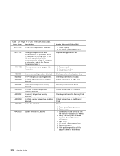
Error Code Description 2BA00337 Service Processor reports Memory Critical Over Temperature Slow Shutdown request. 2BA00338 Service Processor reports Generic Fast Shutdown request. 2BA00340 Service Processor reports Locked .... 3. Replace Power Supply. 2. Replace Power Supply. 2. Replace fan 2. 2. Replace I /O Board. (See notes on 3-1.) 1. Replace Power Supply. 2. If problem persists, replace Memory Card. 1. Replace fan 3. 2. Check fans for cool air flow obstructions to the system. 2. Replace I /O Board. (See notes on 3-1.) 1. If problem persi.ts, replace Power...
Error Code Description 2BA00337 Service Processor reports Memory Critical Over Temperature Slow Shutdown request. 2BA00338 Service Processor reports Generic Fast Shutdown request. 2BA00340 Service Processor reports Locked .... 3. Replace Power Supply. 2. Replace Power Supply. 2. Replace fan 2. 2. Replace I /O Board. (See notes on 3-1.) 1. Replace Power Supply. 2. If problem persists, replace Memory Card. 1. Replace fan 3. 2. Check fans for cool air flow obstructions to the system. 2. Replace I /O Board. (See notes on 3-1.) 1. If problem persi.ts, replace Power...
Service Guide
Page 92
... /O board. (See notes on 3-1.) 5. System fans. 1. Surveillance mode control is failing. A CPU temperature warning detected. A memory temperature warning detected. Power supply. 2. I /O board. Service processor. 6. Error Code Description 401110C2 A low −12 voltage reading... System firmware IPL failure. I /O board. CPU card. 4. Verify part numbers 3. Install valid cards Cooling problem; Critical temperature on the Memory Card. Action / Possible Failing FRU 1. If the system is not running , refer to the AIX error log to the Service Processor error...
... /O board. (See notes on 3-1.) 5. System fans. 1. Surveillance mode control is failing. A CPU temperature warning detected. A memory temperature warning detected. Power supply. 2. I /O board. Service processor. 6. Error Code Description 401110C2 A low −12 voltage reading... System firmware IPL failure. I /O board. CPU card. 4. Verify part numbers 3. Install valid cards Cooling problem; Critical temperature on the Memory Card. Action / Possible Failing FRU 1. If the system is not running , refer to the AIX error log to the Service Processor error...

Service Guide
Page 98
Use these values to &hdref refid=1540. Table 3-2. Memory Module PD bits PD value Size 58 32MB 38 128MB Clock Cycle (nsecs) 10 10 Parity/ ECC ECC ECC Note: Memory modules must be installed in the tables. If you replace FRUs and the problem is the PD values in the table below. Memory PD Bits The following table expands the firmware error code 25Cyyxxx on page 3-9, where yy is still not corrected, go to identify the type of memory that generated the error. unless otherwise indicated in pairs. 3-26 Service Guide
Use these values to &hdref refid=1540. Table 3-2. Memory Module PD bits PD value Size 58 32MB 38 128MB Clock Cycle (nsecs) 10 10 Parity/ ECC ECC ECC Note: Memory modules must be installed in the tables. If you replace FRUs and the problem is the PD values in the table below. Memory PD Bits The following table expands the firmware error code 25Cyyxxx on page 3-9, where yy is still not corrected, go to identify the type of memory that generated the error. unless otherwise indicated in pairs. 3-26 Service Guide

Service Guide
Page 104
... E104 E105 E108 E109 E10A E10B E10C E10D E10E E10F E110 E111 E112 E113 E114 E115 Reserved Video enabled, extended memory test Firmware restart Set memory refresh (composite img) Set memory refresh (recovery block) Transfer control to RAM BAD CRC - copy uncompressed recovery block code to Operating System (normal boot...3-29. See the note on 3-29. See the note on 3-29. See the note on 3-29. See the note on 3-29. initialize base memory, stack BAD CRC - See the note on 3-29. 3-32 Service Guide jump to composite image BAD CRC - turn on cache Action/ Possible Failing FRU...
... E104 E105 E108 E109 E10A E10B E10C E10D E10E E10F E110 E111 E112 E113 E114 E115 Reserved Video enabled, extended memory test Firmware restart Set memory refresh (composite img) Set memory refresh (recovery block) Transfer control to RAM BAD CRC - copy uncompressed recovery block code to Operating System (normal boot...3-29. See the note on 3-29. See the note on 3-29. See the note on 3-29. See the note on 3-29. initialize base memory, stack BAD CRC - See the note on 3-29. 3-32 Service Guide jump to composite image BAD CRC - turn on cache Action/ Possible Failing FRU...

Service Guide
Page 105
... the note on 3-29. Chapter 3. See the note on 3-29. 1. E123 E124 E125 E126 E127 E128 E129 E12A E12B E12C E12D E12E E12F No memory module found in parking lot Primary processor sync Unexpected return from Open Firmware (system lockup) Action/ Possible Failing FRU See the note on cache Copy... RAM Invalidate and flush cache, set TOC Branch to high level recovery control routine. See the note on 3-29. See the note on continuously. No memory detected (system lockup) Note: Disk drive light is on 3-29. See the note on 3-29. See the note on 3-29. copy recovery block ...
... the note on 3-29. Chapter 3. See the note on 3-29. 1. E123 E124 E125 E126 E127 E128 E129 E12A E12B E12C E12D E12E E12F No memory module found in parking lot Primary processor sync Unexpected return from Open Firmware (system lockup) Action/ Possible Failing FRU See the note on cache Copy... RAM Invalidate and flush cache, set TOC Branch to high level recovery control routine. See the note on 3-29. See the note on continuously. No memory detected (system lockup) Note: Disk drive light is on 3-29. See the note on 3-29. See the note on 3-29. copy recovery block ...

Service Guide
Page 106
... E136 E137 E138 E139 E13A E140 E149 E14C E14D Build device tree Create ROOT node Create cpus node Create L2 Cache node Create memory node Create memory module node Test memory Create openprom node Create options node Create aliases node and system aliases Create packages node PReP style load Create boot mgr node...
... E136 E137 E138 E139 E13A E140 E149 E14C E14D Build device tree Create ROOT node Create cpus node Create L2 Cache node Create memory node Create memory module node Test memory Create openprom node Create options node Create aliases node and system aliases Create packages node PReP style load Create boot mgr node...


